Yamaha LS9 Le manuel du propriétaire
- Catégorie
- Mélangeurs audio
- Taper
- Le manuel du propriétaire

Owner’s Manual
LS9-16/LS9-32
EN

2
LS9-16/32 Owner’s Manual
* This applies only to products distributed by YAMAHA CORPORATION OF AMERICA. (Perchlorate)
This product contains a battery that contains perchlorate material.
Perchlorate Material—special handling may apply,
See www.dtsc.ca.gov/hazardouswaste/perchlorate.
* This applies only to products distributed by YAMAHA CORPORATION OF AMERICA. (class B)
FCC INFORMATION (U.S.A.)
1. IMPORTANT NOTICE: DO NOT MODIFY THIS
UNIT!
This product, when installed as indicated in the instructions
contained in this manual, meets FCC requirements. Modifi-
cations not expressly approved by Yamaha may void your
authority, granted by the FCC, to use the product.
2. IMPORTANT: When connecting this product to accesso-
ries and/or another product use only high quality shielded
cables. Cable/s supplied with this product MUST be used.
Follow all installation instructions. Failure to follow instruc-
tions could void your FCC authorization to use this product
in the USA.
3. NOTE: This product has been tested and found to comply
with the requirements listed in FCC Regulations, Part 15 for
Class “B” digital devices. Compliance with these require-
ments provides a reasonable level of assurance that your
use of this product in a residential environment will not
result in harmful interference with other electronic devices.
This equipment generates/uses radio frequencies and, if
not installed and used according to the instructions found in
the users manual, may cause interference harmful to the
operation of other electronic devices. Compliance with FCC
regulations does not guarantee that interference will not
occur in all installations. If this product is found to be the
source of interference, which can be determined by turning
the unit “OFF” and “ON”, please try to eliminate the problem
by using one of the following measures:
Relocate either this product or the device that is being
affected by the interference.
Utilize power outlets that are on different branch (circuit
breaker or fuse) circuits or install AC line filter/s.
In the case of radio or TV interference, relocate/reorient the
antenna. If the antenna lead-in is 300 ohm ribbon lead,
change the lead-in to co-axial type cable.
If these corrective measures do not produce satisfactory
results, please contact the local retailer authorized to dis-
tribute this type of product. If you can not locate the appro-
priate retailer, please contact Yamaha Corporation of
America, Electronic Service Division, 6600 Orangethorpe
Ave, Buena Park, CA90620
The above statements apply ONLY to those products dis-
tributed by Yamaha Corporation of America or its subsidiar-
ies.
* This applies only to products distributed by
YAMAHA CORPORATION OF AMERICA.
COMPLIANCE INFORMATION STATEMENT
(DECLARATION OF CONFORMITY PROCEDURE)
Responsible Party : Yamaha Corporation of America
Address : 6600 Orangethorpe Ave., Buena Park,
Calif. 90620
Telephone : 714-522-9011
Type of Equipment : DIGITAL MIXING CONSOLE
Model Name : LS9-16, LS9-32
This device complies with Part 15 of the FCC Rules.
Operation is subject to the following two conditions:
1) this device may not cause harmful interference, and
2) this device must accept any interference received including
interference that may cause undesired operation.
See user manual instructions if interference to radio recep-
tion is suspected.
(FCC DoC)
IMPORTANT NOTICE FOR THE UNITED KINGDOM
Connecting the Plug and Cord
WARNING: THIS APPARATUS MUST BE EARTHED
IMPORTANT. The wires in this mains lead are coloured in
accordance with the following code:
GREEN-AND-YELLOW : EARTH
BLUE : NEUTRAL
BROWN : LIVE
As the colours of the wires in the mains lead of this apparatus
may not correspond with the coloured markings identifying the
terminals in your plug proceed as follows:
The wire which is coloured GREEN-and-YELLOW must be
connected to the terminal in the plug which is marked by the
letter E or by the safety earth symbol or colored GREEN or
GREEN-and-YELLOW.
The wire which is coloured BLUE must be connected to the
terminal which is marked with the letter N or coloured BLACK.
The wire which is coloured BROWN must be connected to the
terminal which is marked with the letter L or coloured RED.
(3 wires)
This product contains a high intensity lamp that contains
a small amount of mercury. Disposal of this material
may be regulated due to environmental considerations.
For disposal information in the United States, refer to
the Electronic Industries Alliance web site:
www.eiae.org
(mercury)* This applies only to products distributed by
YAMAHA CORPORATION OF AMERICA.

3
LS9-16/32 Owner’s Manual
The above warning is located on the rear or side of the unit.
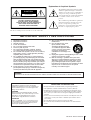
Explanation of Graphical Symbols
The lightning flash with arrowhead symbol
within an equilateral triangle is intended to
alert the user to the presence of uninsulated
“dangerous voltage” within the product’s
enclosure that may be of sufficient magnitude
to constitute a risk of electric shock to
persons.
The exclamation point within an equilateral
triangle is intended to alert the user to the
presence of important operating and
maintenance (servicing) instructions in the
literature accompanying the product.
IMPORTANT SAFETY INSTRUCTIONS
1 Read these instructions.
2Keep these instructions.
3 Heed all warnings.
4 Follow all instructions.
5 Do not use this apparatus near water.
6 Clean only with dry cloth.
7 Do not block any ventilation openings. Install in
accordance with the manufacturer’s instructions.
8 Do not install near any heat sources such as radiators,
heat registers, stoves, or other apparatus (including
amplifiers) that produce heat.
9 Do not defeat the safety purpose of the polarized or
grounding-type plug. A polarized plug has two blades
with one wider than the other. A grounding type plug
has two blades and a third grounding prong. The wide
blade or the third prong are provided for your safety. If
the provided plug does not fit into your outlet, consult
an electrician for replacement of the obsolete outlet.
10 Protect the power cord from being walked on or
pinched particularly at plugs, convenience receptacles,
and the point where they exit from the apparatus.
11 Only use attachments/accessories specified by the
manufacturer.
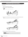
12 Use only with the cart, stand,
tripod, bracket, or table
specified by the manufacturer,
or sold with the apparatus. When
a cart is used, use caution when
moving the cart/apparatus
combination to avoid injury from
tip-over.
13 Unplug this apparatus during lightning storms or when
unused for long periods of time.
14 Refer all servicing to qualified service personnel.
Servicing is required when the apparatus has been
damaged in any way, such as power-supply cord or
plug is damaged, liquid has been spilled or objects
have fallen into the apparatus, the apparatus has been
exposed to rain or moisture, does not operate
normally, or has been dropped.
(98-6500)
CAUTION: TO REDUCE THE RISK OF
ELECTRIC SHOCK, DO NOT REMOVE
COVER (OR BACK). NO USER-SERVICEABLE
PARTS INSIDE. REFER SERVICING TO
QUALIFIED SERVICE PERSONNEL.
CAUTION
RISK OF ELECTRIC SHOCK
DO NOT OPEN
WARNING
TO REDUCE THE RISK OF FIRE OR ELECTRIC SHOCK, DO NOT EXPOSE THIS APPARATUS TO RAIN OR MOISTURE.
ADVARSEL!
Lithiumbatteri—Eksplosionsfare ved fejlagtig
håndtering. Udskiftning må kun ske med batteri af
samme fabrikat og type. Levér det brugte batteri
tilbage til leverandoren.
VARNING
Explosionsfara vid felaktigt batteribyte. Använd
samma batterityp eller en ekvivalent typ som reko-
mmenderas av apparattillverkaren. Kassera
använt batteri enligt fabrikantens instruktion.
VAROITUS
Paristo voi räjähtää, jos se on virheellisesti asen-
nettu. Vaihda paristo ainoastaan laitevalmistajan
suosittelemaan tyyppiin. Hävitä käytetty paristo
valmistajan ohjeiden mukaisesti.
(lithium caution)
NEDERLAND / THE NETHERLANDS
• Dit apparaat bevat een lithium batterij voor geheugen back-up.
• This apparatus contains a lithium battery for memory back-up.
• Raadpleeg uw leverancier over de verwijdering van de batterij op het
moment dat u het apparaat ann het einde van de levensduur of gelieve
dan contact op te nemen met de vertegenwoordiging van Yamaha in
uw land.
•For the removal of the battery at the moment of the disposal at the end
of life please consult your retailer or Yamaha representative office in
your country.
• Gooi de batterij niet weg, maar lever hem in als KCA.
• Do not throw away the battery. Instead, hand it in as small chemical
waste.
(lithium disposal)

4
LS9-16/32 Owner’s Manual
PRECAUTIONS
PLEASE READ CAREFULLY BEFORE PROCEEDING
* Please keep this manual in a safe place for future reference.
WARNING
Always follow the basic precautions listed below to avoid the possibility of serious injury or even death from
electrical shock, short-circuiting, damages, fire or other hazards. These precautions include, but are not limited
to, the following:
• Only use the voltage specified as correct for the device. The required
voltage is printed on the name plate of the device.
• Use only the included power cord.
If you intend to use the device in an area other than in the one you
purchased, the included power cord may not be compatible. Please check
with your Yamaha dealer.
• Do not place the power cord near heat sources such as heaters or radiators,
and do not excessively bend or otherwise damage the cord, place heavy
objects on it, or place it in a position where anyone could walk on, trip over,
or roll anything over it.
• Be sure to connect to an appropriate outlet with a protective grounding
connection. Improper grounding can result in electrical shock.
• Do not open the device or attempt to disassemble the internal parts or
modify them in any way. The device contains no user-serviceable parts. If it
should appear to be malfunctioning, discontinue use immediately and have
it inspected by qualified Yamaha service personnel.
• Do not expose the device to rain, use it near water or in damp or wet
conditions, or place containers on it containing liquids which might spill
into any openings.
• Never insert or remove an electric plug with wet hands.
• Do not put burning items, such as candles, on the unit. A burning item may
fall over and cause a fire.
• When one of the following problems occur, immediately turn off the power
switch and disconnect the electric plug from the outlet. Then have the
device inspected by Yamaha service personnel.
- The power cord or plug becomes frayed or damaged.
- It emits unusual smells or smoke.
- Some object has been dropped into the instrument.
- There is a sudden loss of sound during use of the device.
• If this device should be dropped or damaged, immediately turn off the
power switch, disconnect the electric plug from the outlet, and have the
device inspected by qualified Yamaha service personnel.
CAUTION
Always follow the basic precautions listed below to avoid the possibility of physical injury to you or others, or
damage to the device or other property. These precautions include, but are not limited to, the following:
• Remove the electric plug from the outlet when the device is not to be used
for extended periods of time, or during electrical storms.
• When removing the electric plug from the device or an outlet, always hold
the plug itself and not the cord. Pulling by the cord can damage it.
• When transporting or moving the device, do not hold the display.
Improper transportation can result in injury or damage to the device itself.
• Before moving the device, remove all connected cables.
• When setting up the product, make sure that the AC outlet you are using is
easily accessible. If some trouble or malfunction occurs, immediately turn
off the power switch and disconnect the plug from the outlet. Even when the
power switch is turned off, electricity is still flowing to the product at the
minimum level. When you are not using the product for a long time, make
sure to unplug the power cord from the wall AC outlet.
Power supply/Power cord
Do not open
Water warning
Fire warning
If you notice any abnormality
Power supply/Power cord Location
PA_en_1 1/2

5
LS9-16/32 Owner’s Manual
• Do not place the device in a location where it may come into contact with
corrosive gases or salt air. Doing so may result in malfunction.
•Avoid setting all equalizer controls and faders to their maximum.
Depending on the condition of the connected devices, doing so may cause
feedback and may damage the speakers.
• Do not expose the device to excessive dust or vibrations, or extreme cold
or heat (such as in direct sunlight, near a heater, or in a car during the day)
to prevent the possibility of panel disfiguration or damage to the internal
components.
• Do not place the device in an unstable position where it might accidentally
fall over.
• Do not block the vents. This device has ventilation holes at the top and rear
to prevent the internal temperature from becoming too high. In particular,
do not place the device on its side or upside down. Inadequate ventilation
can result in overheating, possibly causing damage to the device(s), or
even fire.
• Do not use the device in the vicinity of a TV, radio, stereo equipment,
mobile phone, or other electric devices. Doing so may result in noise, both
in the device itself and in the TV or radio next to it.
• Before connecting the device to other devices, turn off the power for all
devices. Before turning the power on or off for all devices, set all volume
levels to minimum.
• Be sure to connect to a properly grounded power source. A ground screw is
provided on the rear panel of this device for maximum safety and shock
prevention. If the mains outlet is not grounded, be sure to connect the
ground screw to a confirmed ground point before plugging the device into
the mains. Improper grounding can result in electrical shock.
• When turning on the AC power in your audio system, always turn on the
power amplifier LAST, to avoid speaker damage. When turning the power
off, the power amplifier should be turned off FIRST for the same reason.
• Do not insert your fingers or hands in any gaps or openings on the device
(vents, etc.).
•Avoid inserting or dropping foreign objects (paper, plastic, metal, etc.) into
any gaps or openings on the device (vents, etc.) If this happens, turn off the
power immediately and unplug the power cord from the AC outlet. Then
have the device inspected by qualified Yamaha service personnel.
• Do not apply oil, grease, or contact cleaner to the faders. Doing so may
cause problems with electrical contact or fader motion.
• Do not use the device or headphones for a long period of time at a high or
uncomfortable volume level, since this can cause permanent hearing loss.
If you experience any hearing loss or ringing in the ears, consult a
physician.
• Do not rest your weight on the device or place heavy objects on it, and
avoid use excessive force on the buttons, switches or connectors.
• This device has a built-in backup battery. When you unplug the power cord
from the AC outlet, the current scene data and library data is retained.
However, if the backup battery fully discharges, this data will be lost. When
the backup battery is running low, the LCD display indicates “Low Battery!”
when you starting up the system (the Battery field also indicates “LOW” or
“NO” in the MISC SETUP screen.) In this case, immediately save the data
to a USB memory, then have qualified Yamaha service personnel replace
the backup battery.
Always turn the power off when the device is not in use.
The performance of components with moving contacts, such as switches, volume controls, and connectors, deteriorates over time. Consult qualified Yamaha service
personnel about replacing defective components.
Connections
Handling caution
Backup battery
XLR-type connectors are wired as follows (IEC60268 standard): pin 1: ground, pin 2: hot (+), and pin 3: cold (-).
Yamaha cannot be held responsible for damage caused by improper use or modifications to the device, or data that is lost or destroyed.
PA_en_1 2/2

6
LS9-16/32 Owner’s Manual
1. Introduction 9
Thank you ...................................................................9
An overview of the LS9.............................................. 9
Differences between the LS9-16 and LS9-32 ......... 11
Number of INPUT channels................................. 11
Rear panel ........................................................... 11
Top panel............................................................. 12
Other.................................................................... 13
The LS9’s channel structure ...................................13
About the MIX bus types (VARI / FIXED)................ 14
About word clock .....................................................14
Conventions in this manual.....................................14
About the firmware version..................................... 14
2. Parts and their function 15
Top panel...................................................................15
Rear panel ................................................................. 23
Front panel................................................................ 26
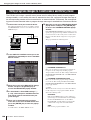
3. Basic operations on the LS9 27
Basic operations in the top panel........................... 27
About the [HOME] key......................................... 27
Selecting the fader layer...................................... 27
Using the SELECTED CHANNEL section........... 29
Selecting functions ..............................................29
Viewing the display .................................................. 30
Constant display area.......................................... 30
Main area............................................................. 31
The on-screen user interface............................... 32
Assigning a name..................................................... 34
Using the tool buttons ............................................. 35
About the tool buttons.......................................... 35
Using libraries...................................................... 35
Initializing settings ...............................................38
Copying and pasting settings ..............................39
Comparing two sets of settings ...........................39
4. Connections and setup 41
Connections.............................................................. 41
Installing an option card.......................................... 44
Setup required when starting up ............................ 45
Returning the current scene to the initial state ....45
Word clock connection and settings .................... 46
HA (head amp) settings....................................... 47
Sending an input channel signal
to the STEREO bus.......................................... 50
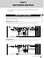
5. Input channel operations 53
Signal flow for input channels.................................53
Specifying the channel name / icon........................55
HA (head amp) settings............................................57
Sending the signal from
an input channel to the STEREO/MONO bus......58
Sending the signal from
an input channel to a MIX bus..............................62
Using the SELECTED CHANNEL section ...........62
Using a popup window.........................................64
Using the faders (SENDS ON FADER mode) .....65
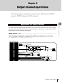
6. Output channel operations 67
Signal flow for output channels ..............................67
Specifying the channel name / icon........................69
Sending signals from MIX channels
to the STEREO/MONO bus ...................................71
Sending signals from MIX channels
and STEREO/MONO channels
to MATRIX buses...................................................75
Using the SELECTED CHANNEL section ...........75
Using a popup window.........................................77
Using the faders (SENDS ON FADER mode) .....78
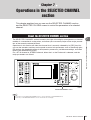
7. Operations in
the SELECTED CHANNEL section 81
About the SELECTED CHANNEL section...............81
About the SELECTED CH VIEW screen..................82
Operations in the SELECTED CHANNEL section..83
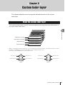
8. Custom fader layer 91
About the custom fader layer ..................................91
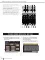
Assigning channels to the custom fader layer ......92
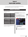
9. Input/output patching 95
Changing the output patching.................................95
Changing the input patching ...................................99
Inserting an external device into a channel .........101
Directly outputting an INPUT channel ..................103
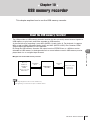
10. USB memory recorder 105
About the USB memory recorder..........................105
Assigning channels to
the input/output of the recorder.........................106
Recording to USB memory ....................................108
Playing back audio files from USB memory ........110
Editing the title list..................................................112
Linking scene recall with audio file playback ......113
Contents

7
LS9-16/32 Owner’s Manual
Contents
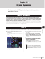
11. EQ and Dynamics 115
About EQ and dynamics........................................ 115
Using EQ .................................................................115
Using dynamics...................................................... 117
Using the EQ/Dynamics libraries.......................... 120
EQ library........................................................... 120
Dynamics library ................................................ 120
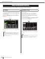
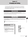
12. Grouping and linking 121
About mute groups ................................................ 121
Using mute groups................................................. 121
Using the MUTE GROUP screen
to operate mute groups .................................. 121
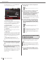
Using the SELECTED CH VIEW screen
to specify mute groups ................................... 122
Using the Mute Safe function ............................123
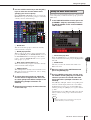
The Channel Link function .................................... 124
Linking the desired input channels ....................124
Copying, moving, or initializing a channel...........126
Copying the parameters of a channel................ 126
Moving the parameters of a channel .................127
Initializing the parameters of a channel ............. 128
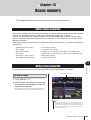
13. Scene memory 129
About scene memories.......................................... 129
Using scene memories ..........................................129
Storing a scene.................................................. 129
Recalling a scene ..............................................131
Using user-defined keys to recall ......................132
Editing scene memories ........................................ 134
Sorting and renaming scene memories............. 134
Scene memory editing....................................... 136
Copying/pasting a scene ...................................136
Clearing a scene................................................ 137
Cutting a scene.................................................. 138
Inserting a scene ...............................................138
Using the Focus function ...................................... 139
Using the Recall Safe function..............................140
Using the Fade function.........................................143
14. Monitor/Cue 145
About the monitor/cue functions.......................... 145
Using the Monitor function....................................146
Using the Cue function .......................................... 148
About cue groups ..............................................148
Operating the Cue function................................ 149
15. Talkback / Oscillator 151
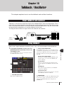
About talkback and oscillator................................151
Using talkback ........................................................151
Using the oscillator ................................................153
16. Meters 155
Using the METER screen .......................................155
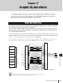
17. Graphic EQ and effects 157
About the virtual rack.............................................157
Mounting a GEQ or effect in the virtual rack ......158
Graphic EQ operations...........................................161
About the graphic EQ.........................................161
Inserting a GEQ in a channel.............................161
Using the 31 Band GEQ ....................................163
Using the Flex15GEQ ........................................164
About the internal effects ......................................166
Using an internal effect via send/return .............167
Inserting an internal effect into a channel ..........168
Editing the internal effect parameters ................170
Using the Tap Tempo function...........................172
Using the Freeze effect......................................173
Using the graphic EQ and effect libraries ............174
GEQ library ........................................................174
Effect library .......................................................174
Using an external head amp ..................................175
Remotely controlling an external head amp.......175
18. MIDI 177
MIDI functionality on the LS9 ................................177
Basic MIDI settings.................................................178
Using program changes
to recall scenes and library items......................180
Using control changes to control parameters .....183
Using parameter changes
to control parameters .........................................185
Using MMC (MIDI Machine Control)
to operate the USB memory recorder ...............186
19. User settings (Security) 187
User Level settings.................................................187
User types and user authentication keys ...........187
Setting the Administrator password ...................188
Creating a user authentication key ....................188
Logging-in ..........................................................189
Changing the password .....................................191
Editing a user authentication key .......................192
Changing the user level .....................................192

8
LS9-16/32 Owner’s Manual
Contents
Preferences............................................................. 194
User-defined keys .................................................. 196
Console lock ........................................................... 197
Locking the console........................................... 197
Unlocking the console .......................................198
Specifying the CONSOLE LOCK
screen image.................................................. 198
Using USB memory to save/load data.................. 199
Saving the LS9’s internal data
on USB memory............................................. 199
Loading a file from USB memory....................... 200
Editing the files saved on USB memory ............201
Formatting USB memory media ........................204
20. Other functions 205
About the SETUP screen ....................................... 205
Word clock settings ............................................... 206
Switching a digital I/O card’s SRC on/off............. 208
Using cascade connections .................................. 209
Operations on the cascade slave LS9............... 210
Operations on the cascade master LS9 ............212
Basic settings for MIX buses and
MATRIX buses..................................................... 213
Setting the date and time of the internal clock.... 215
Setting the network address ................................. 216
Specifying the brightness or
contrast of the display, LEDs, and lamps......... 217
Using the Help function ......................................... 218
Loading a Help file from a USB memory ...........218
Loading a text file from a USB memory............. 219
Assigning the Help function to
a user-defined key.......................................... 219
Viewing Help...................................................... 220
Initializing the LS9’s internal memory.................. 222
Adjusting the faders (Calibration function) ......... 223
Adjusting the input/output gain
(Calibration function).......................................... 224
Appendices 225
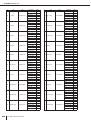
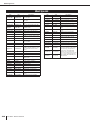
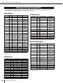
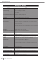
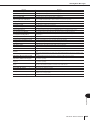
EQ Library List........................................................ 225
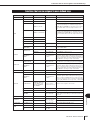
DYNAMICS Library List.......................................... 227
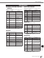
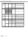
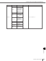
Dynamics Parameters ............................................229
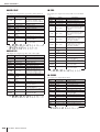
Effect Type List....................................................... 232
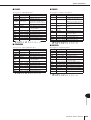
Effects Parameters .................................................233
Effects and tempo synchronization...................... 244
Scene Memory/Effect Library
to Program Change Table ..................................245
Parameters that can be assigned
to control changes ..............................................249
Control change parameter assignments.............. 251
NRPN parameter assignments ..............................253
Mixing parameter operation applicability............. 256
Functions that can be assigned
to user-defined keys ........................................... 257
MIDI Data Format ....................................................260
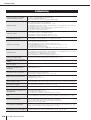
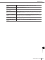
Warning/Error Messages .......................................268
Troubleshooting .....................................................270
General Specifications........................................... 272
Input/output characteristics ..................................273
Electrical characteristics ....................................... 275
Mixer Basic Parameters .........................................277
Pin Assignment ......................................................278
Dimensions .............................................................279
Attaching the RK1 rackmount kit
(sold separately).................................................. 280
MIDI Implementation Chart .................................... 281
Index ........................................................................ 282
Block Diagram ..................................... End of Manual
Level Diagram ...................................... End of Manual
• The illustrations and screen displays as shown in this Owner’s manual are for instructional purposes
only, and may be different from the ones on your device.
• The bitmap fonts used in this device have been provided by and are the property of Ricoh Co., Ltd.
• The company names and product names in this Owner’s Manual are the trademarks or registered
trademarks of their respective companies.
• MPEG Layer-3 audio coding technology licensed from Fraunhofer IIS and Thomson.

9
1
Introduction
LS9-16/32 Owner’s Manual
Chapter 1
Introduction
Thank you for purchasing the Yamaha LS9 digital mixing console. In order to take full advantage
of the LS9’s superior functionality and enjoy years of trouble-free use, please read this manual
before you begin using the product. After you have read the manual, keep it in a safe place.
The LS9 is a digital mixing console with the following features.
■
Mixing system that packs top-class
functionality into a compact size
• • • • •
The LS9 is a full-digital mixing console designed for
installed systems or SR applications, and in spite of its
compact size, provides functionality and a channel count
comparable to large-format consoles. 24-bit linear AD/DA
converters are used to deliver up to 108 dB of dynamic
range and amazing sound quality.
As input channels, it provides 32 (LS9-16 model) or 64
(LS9-32 model) monaural INPUT channels, and four ste-
reo ST IN channels.
As output channels, it provides 16 MIX channels, eight
MATRIX channels, a STEREO channel, and a MONO
channel. L/C/R three-channel output using the STEREO/
MONO channels is also supported.
■
Analog-feeling operability
• • • • • • • • • •
Simply by pressing a key, you can select the combination
of channels (“fader layer”) to be operated from the top
panel faders. You can operate the console while quickly
switching between input channels and output channels. In
addition, you can also use a custom fader layer that lets
you specify any desired combination of channels. Since
fader/cue operations and on/off switching for all channels
can be performed from the panel, even customers using
digital consoles for the first time will find operation famil-
iar and comfortable.
The SELECTED CHANNEL section located at the right
of the display lets you use the knobs to control the main
parameters (gain, EQ, dynamics threshold, bus send lev-
els, etc.) for the particular channel on which you’re focus-
ing. This section can be operated just like a module on an
analog mixer.
Mix parameter settings, including head amp gain and
phantom power for input channels, can be stored and
recalled as “scenes.”
All faders on the panel are motorized moving faders, so
that when you recall a scene, the previous fader locations
are reproduced immediately.
Thank you
An overview of the LS9

10
An overview of the LS9
LS9-16/32 Owner’s Manual
■
Effects and graphic EQ that can be
patched into a desired signal path
• • • •
There are eight virtual racks, in which you can mount
effects or graphic EQ and then patch them into the desired
signal route. Graphic EQ can be mounted in racks 1–4,
and effects or graphic EQ can be mounted in racks 5–8.
You can simultaneously use up to four high-quality multi-
effects, which include reverb, delay, multi-band compres-
sor, and various modulation-type effects. These can be
used via an internal bus, or inserted into a desired channel.
For the graphic EQ you can select either 31-band graphic
EQ or Flex 15 GEQ. These can be inserted into the desired
channel or output. The Flex 15 GEQ allows you to adjust
the gain for any fifteen of the thirty-one bands. Since two
Flex 15 GEQ units can be mounted in a single virtual rack,
a total of up to sixteen graphic EQ units can be used
simultaneously.
■
A recorder function that’s useful for
sound checks or recording mixes
• • • •
A recorder function is provided, allowing you to use USB
memory to record the output of the STEREO bus or a
MIX bus, or assign an audio file in USB memory to a
desired input channel or monitor output and play it back.
Supported file formats are MP3 (MPEG-1 Audio Layer-3)
for recording, and MP3, WMA (Windows Media Audio),
and MPEG-4 AAC (Advanced Audio Coding) for play-
back. However, DRM (Digital Rights Management) is not
supported. This function is convenient when you want to
record the mix output of a specific bus, or if you want to
play back a song from the speakers during the sound
check.
■
Cascade connections in the digital
domain
• • • • • • • • • • • • • • • • • • • • • • •
A second LS9 console or a digital mixer such as the
Yamaha M7CL or PM5D connected via a digital I/O card
installed in a slot can be cascade-connected in the digital
domain.
Of the MIX buses, MATRIX buses, STEREO (L/R) bus,
MONO buses, and CUE (L/R) bus, the desired buses can
be merged, and all mixed bus signals can be cascaded
individually.
■
Security functions that can be specified
at user-level or system-level
• • • • • • •
User levels can be distinguished into three levels (admin-
istrator, guest, user), and the functionality available to
each non-administrator user can be restricted. Passwords
can be specified for the administrator and users, prevent-
ing important settings from being changed accidentally.
Information specific to each user (user level, system set-
tings, and user-defined key settings) can be stored on USB
memory as a “user authentication key.” By loading your
own user authentication key from USB memory, you can
instantly set up the ideal operating environment for your-
self.
■
I/O card expansion
• • • • • • • • • • • • • •
The rear panel provides one slot (LS9-16) or two slots
(LS9-32) in which separately sold mini-YGDAI cards can
be installed. AD cards, DA cards, or digital I/O cards can
be installed in these slots to add inputs and outputs port.

11
Differences between the LS9-16 and LS9-32
1
Introduction
LS9-16/32 Owner’s Manual
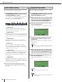
The LS9 is available in two models; the LS9-16 and the LS9-32. These models differ as follows.
The LS9-16 has up to 32 operable INPUT channels, while the LS9-32 has up to 64. The number and structure of other chan-
nels (ST IN channels, MIX channels, MATRIX channels, STEREO/MONO channels) are identical.
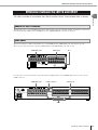
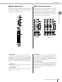
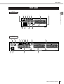
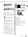
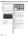
The LS9-16 and LS9-32 differ in the number of rear panel INPUT jacks, OMNI OUT jacks, and slots they provide.
The rear panel of the LS9-16 provides sixteen INPUT jacks, eight OMNI OUT jacks, and one slot.
In contrast, the rear panel of the LS9-32 provides thirty-two INPUT jacks, sixteen OMNI OUT jacks, two slots, and one
LAMP connector.
Differences between the LS9-16 and LS9-32
Number of INPUT channels
Rear panel
INPUT jacksOMNI OUT jacks Slot
OMNI OUT jacks INPUT jacks
Slots
LAMP connector

12
Differences between the LS9-16 and LS9-32
LS9-16/32 Owner’s Manual
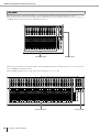
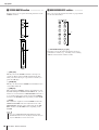
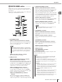
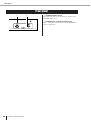
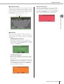
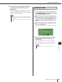
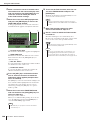
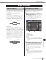
The LS9-16 and LS9-32 differ in the number of top panel channel modules and ST IN channels they provide.
The LS9-16 provides sixteen channel modules and two ST IN channels, and by switching fader layers you can operate up to
32 INPUT channels (monaural) and four ST IN channels (stereo).
The LS9-16 provides thirty-two channel modules and four ST IN channels. By switching fader layers you can operate up to
sixty-four INPUT channels (monaural).
The four ST IN channels (stereo) can be operated from either layer (1-32 or 33-64).
Top panel
Channel modules ST IN channels
Channel modules ST IN channels

13
1
Introduction
LS9-16/32 Owner’s Manual
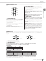
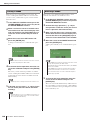
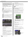
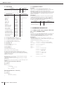
The names of the LAYER section keys differ between the LS9-16 and LS9-32.
● LS9-16 ● LS9-32
In conjunction with this difference, there are also differences in the numbering of the channel modules on the panel and the
channels that are assigned to each fader layer.
The LS9 provides the following input channels and output channels.
■ Input channels • • • • • • • • • • • • • • • • •
This section processes input signals and sends them to
various buses (STEREO, MONO, MIX). The LS9 has the
following two types of input channel.
● INPUT channels 1–32 {1–64}
These channels process monaural signals. In the initial
state, the input signals from the rear panel INPUT jacks
and the input channels of the slot(s) are assigned to these
channels.
● ST IN channels 1–4
These channels process stereo signals. In the initial state,
the outputs of virtual racks 5–8 are assigned to these chan-
nels.
Signal assignments to the input channels (input patching)
can be changed as desired.
■ Output channels • • • • • • • • • • • • • • • •
This section mixes the signals sent from input channels
etc., and sends them to the corresponding output ports or
output buses.
There are three types of output channel, as follows.
● MIX channels 1–16
These channels process the signals sent from input chan-
nels to the MIX buses, and send them from the output
ports. These are used mainly to send signals to the monitor
system or to external effects.
The signals of MIX channels 1–16 can also be sent to the
STEREO bus, MONO bus, or MATRIX buses.
When the LS9 is in the initial state, these are assigned to
the OMNI OUT jacks or the output channels of the slot(s).
● MATRIX channels 1–8
These channels process the signals that are sent from MIX
channels, STEREO channels, and MONO channel to the
MATRIX buses, and send them from the output ports.
Using the STEREO and MONO buses, different combina-
tions of signals and mix balances can be sent out from the
console.
● STEREO channel / MONO channel
These channels process the signals that are sent from the
input channels or MIX channels, and send them to the cor-
responding output port. These channels are used as the
main stereo output and monaural output.
The STEREO channel and MONO channel can be used
either to output independent signals, or for three-channel L/
C/R playback.
When the
LS9
is in the initial state, the STEREO channel is
assigned to OMNI OUT jacks 15/16 {31/32} and to the
2TR OUT DIGITAL jack.
Signal assignments to the output channels (output patch-
ing) can be changed as desired.
Other
LAYER [1-16] key LAYER [17-32] key
LAYER [MASTER] key LAYER [CUSTOM
FADER] key
LAYER [1-32] key LAYER [33-64] key
LAYER [MASTER] key LAYER [CUSTOM
FADER] key
• In this owner’s manual, whenever there is a difference between the LS9-16 model and the LS9-32 model, specifica-
tions that apply only to the LS9-32 model are enclosed in curly brackets { } (e.g., INPUT jacks 1–16 {1–32}).
• When the specifications are common to both models, the manual refers simply to the LS9.
HINT
The LS9’s channel structure
Differences between the LS9-16 and LS9-32 • The LS9’s channel structure

14
LS9-16/32 Owner’s Manual
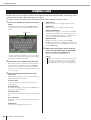
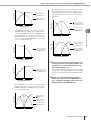
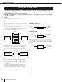
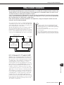
The sixteen MIX buses provided on the LS9 can be assigned either as VARI or FIXED types in
pairs of adjacent odd-numbered/even-numbered buses (→ p. 213). They can also be switched
between monaural/stereo for the same pairs of buses. VARI type and FIXED type buses differ as
follows.
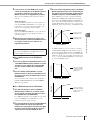
● VARI
This type allows the send level of the signal sent from the
input channels to the MIX bus to be varied. The point at
which the signal is sent from the input channel to a VARI
type MIX bus can be chosen from before the EQ
(attenuator), before the fader, or after the channel on/off.
This type is used mainly for sending the signal to a moni-
tor system or external effect.
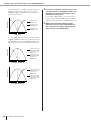
● FIXED
With this type, the send level of the signal sent from the
input channels to the MIX bus is fixed. The signal from an
input channel is sent to a FIXED type MIX bus from
before Pan (if the MIX bus is monaural) or after Pan (if
the MIX bus is stereo). This type is used mainly when you
want to distribute signals to an external device with the
same mix as the STEREO/MONO buses.
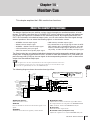
“Word clock” refers to the clock that provides the basis of timing for digital audio signal process-
ing.
Normally, one device transmits a reference word clock signal, and the other devices receive this
word clock signal and synchronize to it.
In order to transmit or receive digital audio signals to or from an external device via the LS9’s
2TR IN DIGITAL/2TR OUT DIGITAL jacks or via a digital I/O card installed in a slot, the word
clock must be synchronized between the devices. Be aware that if the word clock is not synchro-
nized, the signal will not be sent correctly, or there may be unpleasant noise. (For details on syn-
chronizing the LS9’s word clock with an external device → p. 46)
In this manual, switch-type controllers on the panel are called “keys.” Of the control knobs on the
panel, those that turn from a minimum value to a maximum value are called “controls,” while
those that turn endlessly are called “encoders.”
Controllers located on the panel are enclosed in square
brackets [ ] (e.g., [CUE] key) in order to distinguish them
from the virtual buttons and knobs displayed in the screen.
For some controllers, the name of the section is given
before the [ ] (e.g., LAYER [MASTER] key).
Whenever there is a difference between the LS9-16 model
and the LS9-32 model, specifications that apply only to
the LS9-32 model are enclosed in curly brackets { } (e.g.,
INPUT jacks 1–16 {1–32}).
You can view the firmware version number in the MISC SETUP screen (→ p. 206).
You can also download the most recent firmware version from the website.
http://www.yamahaproaudio.com/
About the MIX bus types (VARI / FIXED)
About word clock
Conventions in this manual
About the firmware version
About the MIX bus types (VARI / FIXED) • About word clock • Conventions in this manual • About the firmware version

15
LS9-16/32 Owner’s Manual
2
Parts and their function
Chapter 2
Parts and their function
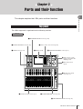
This chapter explains the LS9’s parts and their functions.
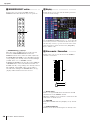
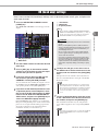
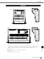
The LS9’s top panel is organized into the following sections.
Top panel
LS9-16
z Channel module section (p. 17) c STEREO MASTER section (p. 18)
v USER DEFINED KEYS section (p. 18)
b DISPLAY ACCESS section (p. 19)
n LAYER section (p. 19)
m MIX/MATRIX SELECT section (p. 20)
, Display (p. 20)
. Stereo meter / Cue section (p. 20)
⁄0 SELECTED CHANNEL section (p. 21)
⁄1 Data entry section
(p. 22)
x ST IN (stereo input)
section (p. 17)
⁄2 USB connector (side
panel, to the right of the
display) (p. 22)

Top panel
16
LS9-16/32 Owner’s Manual
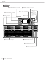
LS9-32
z Channel module section (p. 17) c STEREO MASTER section (p. 18)
v USER DEFINED KEYS section (p. 18)
b DISPLAY ACCESS section (p. 19)
n LAYER section (p. 19)
m MIX/MATRIX SELECT section (p. 20)
, Display (p. 20)
. Stereo meter / Cue section (p. 20)
⁄0 SELECTED CHANNEL section (p. 21)
⁄1 Data entry section
(p. 22)
⁄2 USB connector
(side panel, to the
right of the display)
(p. 22)
x ST IN (stereo input) section (p. 17)

Top panel
LS9-16/32 Owner’s Manual
17
2
Parts and their function
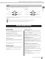
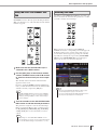
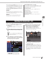
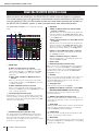
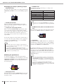
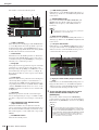
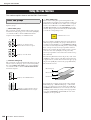
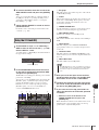
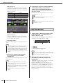
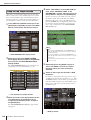
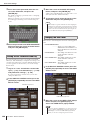
z Channel module section • • • • • • • • • • •
In this section you can operate the main parameters of the
input channels and output channels, as well as the monitor
output. Use the LAYER section (→ p. 19) to select the
channels that are mapped to this section.
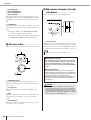
x ST IN (stereo input) section • • • • • • • •
In this section you can operate the main parameters of the
stereo ST IN channels 1–4. The function of each control-
ler is the same as in the Channel Module section, with the
exception that the L-channel or R-channel will be alter-
nately selected as the target of operations each time you
press the [SEL] key, and the fact that the encoder rather
than the fader is used to adjust the level.
1 [SEL] key
This key selects the channel to be operated. When you
press this key to make the LED light, the corresponding
channel will be selected for operations in the SELECTED
CHANNEL section or in the display. In the ST IN section,
the L-channel and R-channel will be alternately selected
as the target of operations each time you press the [SEL]
key.
B [CUE] key
This key selects the channel to be cue-monitored. When
cue is on, the LED will be lit.
C Meter LEDs
These LEDs indicate the audio signal level of the input
channel or output channel.
D [ON] key
This switches the channel on/off. The key LED will light
for channels that are on. In SENDS ON FADER mode,
this key is an on/off switch for the signal that is sent from
that channel to the currently selected MIX bus (or from a
MIX channel, to the MATRIX bus).
E Fader/Encoder
This adjusts the signal level or monitor level of the input
channel or output channel. In SENDS ON FADER mode,
this adjusts the send level from that channel to the cur-
rently selected MIX bus (or from a MIX channel, to the
MATRIX bus).
1
2
4
5
3
1
2
4
5
3
1
2
4
5
3
LS9-32LS9-16

Top panel
18
LS9-16/32 Owner’s Manual
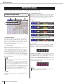
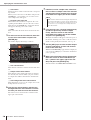
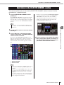
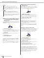
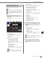
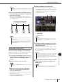
c STEREO MASTER section • • • • • • • • • • •
In this section you can operate the main parameters of the
STEREO channel.
1 [SEL] key
This key selects the STEREO channel as the target of
operations. The L-channel and R-channel will be alter-
nately selected as the target of operations each time you
press the [SEL] key.
B [CUE] key
This key cue-monitors the STEREO channel. When cue is
on, the LED will be lit.
C [ON] key
This switches the STEREO channel on/off. When on, the
key LED will light. In SENDS ON FADER mode, you can
use this as an on/off switch for MIX/MATRIX channels or
as an on/off switch for the signal sent from the STEREO
channel to the MATRIX buses, depending on the LAYER.
D Fader
This adjusts the output level of the STEREO channel. In
SENDS ON FADER mode, this adjusts the level of the
MIX/MATRIX channels or the send level from the STE-
REO channel to the MATRIX buses, depending on the
LAYER.
v USER DEFINED KEYS section• • • • • • • • •
Here you can execute the functions that are programmed
for the user-defined keys.
1 User-defined keys [1]–[12]
These keys execute the functions that have been pro-
grammed for each key (e.g., switching scenes, turning
talkback or the internal oscillator on/off).
1
2
3
4
• If you turn on MONITOR ON MASTER FADER in the USER
DEFINED KEY SETUP screen, the [ON] key and fader will respec-
tively turn MONITOR on/off and control its level.
HINT
1

Top panel
LS9-16/32 Owner’s Manual
19
2
Parts and their function
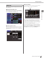
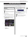
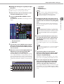
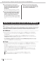
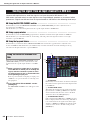
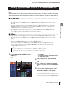
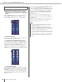
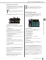
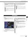
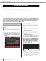
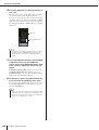
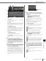
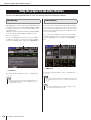
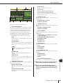
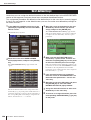
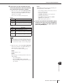
b DISPLAY ACCESS section • • • • • • • • • • • • • • • • • • • • • • • • • • • • • • • • • • • • • • • • • • • •
1 [SCENE MEMORY] key
This key accesses a screen where you can store, recall, and
edit scene memories, and make settings for the Focus
function and Fade Time function.
B [MONITOR] key
This key accesses a screen where you can make settings
for cue, monitor, oscillator, and talkback.
C [SETUP] key
This key accesses a screen where you can set and verify
the user level, and make basic system settings.
D [CHANNEL JOB] key
This key accesses a screen where you can make settings
for Channel Link, Mute Group, and Recall Safe functions,
and copy or move settings between channels.
E [RECORDER] key
This key accesses a screen where you can operate and
make settings for the Recorder function which records and
plays audio files.
F [METER] key
This key accesses a meter screen where you can view the
input/output levels of all channels in a single view.
G [RACK 1-4] key
This key accesses a screen where you can edit the graphic
EQ assigned to virtual racks 1–4. By pressing the [RACK
1-4] key and [RACK 5-8] key simultaneously you can
access the VIRTUAL RACK screen, where you can assign
a graphic EQ (31 Band GEQ or Flex 15 GEQ) to each vir-
tual rack.
H [RACK 5-8] key
This key accesses a screen where you can edit the graphic
EQ or internal effect that is assigned to virtual racks 5–8,
and make settings for external head amps. By pressing the
[RACK 1-4] key and [RACK 5-8] key simultaneously you
can access the VIRTUAL RACK screen, where you can
assign a graphic EQ (31 Band GEQ or Flex 15 GEQ) or
internal effect to each virtual rack.
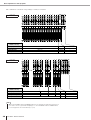
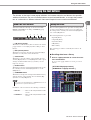
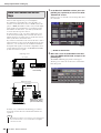
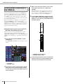
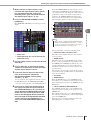
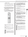
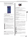
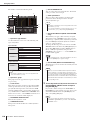
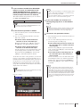
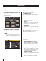
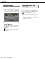
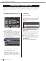
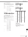
n LAYER section • • • • • • • • • • • • • • • • • • • • • • • • • • • • • • • • • • • • • • • • • • • • • • • • • • •
Here you can select the type of channels that will be operated from the channel module section (→ p. 17) and ST IN section
(→ p. 17).
1 LAYER [1-16] {LAYER [1-32]} key
B LAYER [17-32] {LAYER [33-64]} key
C LAYER [MASTER] key
These keys assign fixed preset combinations of channels to the channel module section and the ST IN
section. The combination of channels corresponding to each key is as follows.
D LAYER [CUSTOM FADER] key
This key assigns the channels selected by you (the user) to the channel module section and the ST IN
section. (For the channel assignment procedure → p. 91)
2
4
6
87
5
3
1
2
43
1 2
43
1
LS9-16 LS9-32
For the LS9-16
LAYER key / module 1–16 ST IN 1–2
LAYER [1-16] key CH 1–16 ST IN 1–2
LAYER [17-32] key CH 17–32 ST IN 3–4
LAYER [MASTER] key MIX 1–16 —
For the LS9-32
LAYER key / module 1–16 17–24 25–31 32 ST IN 1–4
LAYER [1-32] key CH 1–16 CH 17–24 CH 25–31 CH 32 ST IN 1–4
LAYER [33-64] key CH 33–48 CH 49–56 CH 57–63 CH 64 ST IN 1–4
LAYER [MASTER] key MIX 1–16 MATRIX 1–8 — MONO —

Top panel
20
LS9-16/32 Owner’s Manual
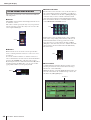
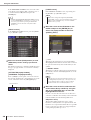
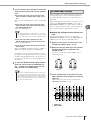
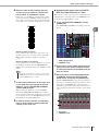
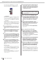
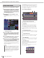
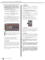
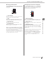
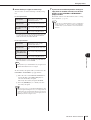
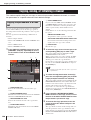
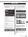
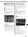
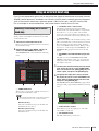
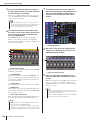
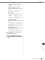
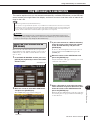
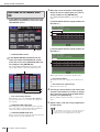
m MIX/MATRIX SELECT section • • • • • • • • •
In this section you can select the MIX channel or
MATRIX channel that will be the object of operations.
1 MIX/MATRIX [1]–[16] keys
These keys select the MIX channel (or if the selected
channel is a MIX/STEREO/MONO channel, the
MATRIX channel) whose send level will be adjusted by
the SELECTED CHANNEL section. The LED of the key
corresponding to the currently selected channel will light
(or blink, in the case of a MATRIX channel).
In SENDS ON FADER mode, these keys select a MIX bus
or MATRIX button as the send-destination. In this case,
the LED of the key corresponding to the currently selected
bus will blink, and the LED of keys corresponding to
selectable buses will light. For MATRIX buses, the [9]–
[16] keys will be dark and cannot be selected.
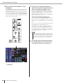
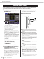
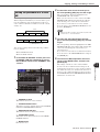
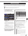
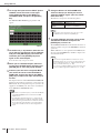
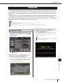
, Display • • • • • • • • • • • • • • • • • • • • • •
In this display you can view and edit all mix parameters,
as well as various settings.
Use the DISPLAY ACCESS section (→ p. 19) to select the
screen that you want to view. Then use the cursor keys of
the data entry section (→ p. 22) to move the cursor to the
desired parameter, and use the dial or the [INC][DEC]
keys to edit the value.
. Stereo meter / Cue section • • • • • • • •
In this section you can view the level of the STEREO
channel or cue monitor.
1 Stereo meter
This is a 32-segment LED meter that indicates the L/R
channel levels of the STEREO channel.
While the [CUE] key of any channel is on, this meter will
indicate the cue monitor level.
B CUE LED
This LED will blink while the [CUE] key of any channel
is on.
C [CUE CLEAR] key
This key clears all cue monitoring that is currently active.
1
1
2
3
La page est en cours de chargement...
La page est en cours de chargement...
La page est en cours de chargement...
La page est en cours de chargement...
La page est en cours de chargement...
La page est en cours de chargement...
La page est en cours de chargement...
La page est en cours de chargement...
La page est en cours de chargement...
La page est en cours de chargement...
La page est en cours de chargement...
La page est en cours de chargement...
La page est en cours de chargement...
La page est en cours de chargement...
La page est en cours de chargement...
La page est en cours de chargement...
La page est en cours de chargement...
La page est en cours de chargement...
La page est en cours de chargement...
La page est en cours de chargement...
La page est en cours de chargement...
La page est en cours de chargement...
La page est en cours de chargement...
La page est en cours de chargement...
La page est en cours de chargement...
La page est en cours de chargement...
La page est en cours de chargement...
La page est en cours de chargement...
La page est en cours de chargement...
La page est en cours de chargement...
La page est en cours de chargement...
La page est en cours de chargement...
La page est en cours de chargement...
La page est en cours de chargement...
La page est en cours de chargement...
La page est en cours de chargement...
La page est en cours de chargement...
La page est en cours de chargement...
La page est en cours de chargement...
La page est en cours de chargement...
La page est en cours de chargement...
La page est en cours de chargement...
La page est en cours de chargement...
La page est en cours de chargement...
La page est en cours de chargement...
La page est en cours de chargement...
La page est en cours de chargement...
La page est en cours de chargement...
La page est en cours de chargement...
La page est en cours de chargement...
La page est en cours de chargement...
La page est en cours de chargement...
La page est en cours de chargement...
La page est en cours de chargement...
La page est en cours de chargement...
La page est en cours de chargement...
La page est en cours de chargement...
La page est en cours de chargement...
La page est en cours de chargement...
La page est en cours de chargement...
La page est en cours de chargement...
La page est en cours de chargement...
La page est en cours de chargement...
La page est en cours de chargement...
La page est en cours de chargement...
La page est en cours de chargement...
La page est en cours de chargement...
La page est en cours de chargement...
La page est en cours de chargement...
La page est en cours de chargement...
La page est en cours de chargement...
La page est en cours de chargement...
La page est en cours de chargement...
La page est en cours de chargement...
La page est en cours de chargement...
La page est en cours de chargement...
La page est en cours de chargement...
La page est en cours de chargement...
La page est en cours de chargement...
La page est en cours de chargement...
La page est en cours de chargement...
La page est en cours de chargement...
La page est en cours de chargement...
La page est en cours de chargement...
La page est en cours de chargement...
La page est en cours de chargement...
La page est en cours de chargement...
La page est en cours de chargement...
La page est en cours de chargement...
La page est en cours de chargement...
La page est en cours de chargement...
La page est en cours de chargement...
La page est en cours de chargement...
La page est en cours de chargement...
La page est en cours de chargement...
La page est en cours de chargement...
La page est en cours de chargement...
La page est en cours de chargement...
La page est en cours de chargement...
La page est en cours de chargement...
La page est en cours de chargement...
La page est en cours de chargement...
La page est en cours de chargement...
La page est en cours de chargement...
La page est en cours de chargement...
La page est en cours de chargement...
La page est en cours de chargement...
La page est en cours de chargement...
La page est en cours de chargement...
La page est en cours de chargement...
La page est en cours de chargement...
La page est en cours de chargement...
La page est en cours de chargement...
La page est en cours de chargement...
La page est en cours de chargement...
La page est en cours de chargement...
La page est en cours de chargement...
La page est en cours de chargement...
La page est en cours de chargement...
La page est en cours de chargement...
La page est en cours de chargement...
La page est en cours de chargement...
La page est en cours de chargement...
La page est en cours de chargement...
La page est en cours de chargement...
La page est en cours de chargement...
La page est en cours de chargement...
La page est en cours de chargement...
La page est en cours de chargement...
La page est en cours de chargement...
La page est en cours de chargement...
La page est en cours de chargement...
La page est en cours de chargement...
La page est en cours de chargement...
La page est en cours de chargement...
La page est en cours de chargement...
La page est en cours de chargement...
La page est en cours de chargement...
La page est en cours de chargement...
La page est en cours de chargement...
La page est en cours de chargement...
La page est en cours de chargement...
La page est en cours de chargement...
La page est en cours de chargement...
La page est en cours de chargement...
La page est en cours de chargement...
La page est en cours de chargement...
La page est en cours de chargement...
La page est en cours de chargement...
La page est en cours de chargement...
La page est en cours de chargement...
La page est en cours de chargement...
La page est en cours de chargement...
La page est en cours de chargement...
La page est en cours de chargement...
La page est en cours de chargement...
La page est en cours de chargement...
La page est en cours de chargement...
La page est en cours de chargement...
La page est en cours de chargement...
La page est en cours de chargement...
La page est en cours de chargement...
La page est en cours de chargement...
La page est en cours de chargement...
La page est en cours de chargement...
La page est en cours de chargement...
La page est en cours de chargement...
La page est en cours de chargement...
La page est en cours de chargement...
La page est en cours de chargement...
La page est en cours de chargement...
La page est en cours de chargement...
La page est en cours de chargement...
La page est en cours de chargement...
La page est en cours de chargement...
La page est en cours de chargement...
La page est en cours de chargement...
La page est en cours de chargement...
La page est en cours de chargement...
La page est en cours de chargement...
La page est en cours de chargement...
La page est en cours de chargement...
La page est en cours de chargement...
La page est en cours de chargement...
La page est en cours de chargement...
La page est en cours de chargement...
La page est en cours de chargement...
La page est en cours de chargement...
La page est en cours de chargement...
La page est en cours de chargement...
La page est en cours de chargement...
La page est en cours de chargement...
La page est en cours de chargement...
La page est en cours de chargement...
La page est en cours de chargement...
La page est en cours de chargement...
La page est en cours de chargement...
La page est en cours de chargement...
La page est en cours de chargement...
La page est en cours de chargement...
La page est en cours de chargement...
La page est en cours de chargement...
La page est en cours de chargement...
La page est en cours de chargement...
La page est en cours de chargement...
La page est en cours de chargement...
La page est en cours de chargement...
La page est en cours de chargement...
La page est en cours de chargement...
La page est en cours de chargement...
La page est en cours de chargement...
La page est en cours de chargement...
La page est en cours de chargement...
La page est en cours de chargement...
La page est en cours de chargement...
La page est en cours de chargement...
La page est en cours de chargement...
La page est en cours de chargement...
La page est en cours de chargement...
La page est en cours de chargement...
La page est en cours de chargement...
La page est en cours de chargement...
La page est en cours de chargement...
La page est en cours de chargement...
La page est en cours de chargement...
La page est en cours de chargement...
La page est en cours de chargement...
La page est en cours de chargement...
La page est en cours de chargement...
La page est en cours de chargement...
La page est en cours de chargement...
La page est en cours de chargement...
La page est en cours de chargement...
La page est en cours de chargement...
La page est en cours de chargement...
La page est en cours de chargement...
La page est en cours de chargement...
La page est en cours de chargement...
La page est en cours de chargement...
La page est en cours de chargement...
La page est en cours de chargement...
La page est en cours de chargement...
La page est en cours de chargement...
La page est en cours de chargement...
La page est en cours de chargement...
La page est en cours de chargement...
La page est en cours de chargement...
La page est en cours de chargement...
La page est en cours de chargement...
La page est en cours de chargement...
La page est en cours de chargement...
La page est en cours de chargement...
La page est en cours de chargement...
La page est en cours de chargement...
La page est en cours de chargement...
La page est en cours de chargement...
La page est en cours de chargement...
La page est en cours de chargement...
La page est en cours de chargement...
La page est en cours de chargement...
La page est en cours de chargement...
La page est en cours de chargement...
La page est en cours de chargement...
La page est en cours de chargement...
La page est en cours de chargement...
La page est en cours de chargement...
La page est en cours de chargement...
La page est en cours de chargement...
La page est en cours de chargement...
La page est en cours de chargement...
-
 1
1
-
 2
2
-
 3
3
-
 4
4
-
 5
5
-
 6
6
-
 7
7
-
 8
8
-
 9
9
-
 10
10
-
 11
11
-
 12
12
-
 13
13
-
 14
14
-
 15
15
-
 16
16
-
 17
17
-
 18
18
-
 19
19
-
 20
20
-
 21
21
-
 22
22
-
 23
23
-
 24
24
-
 25
25
-
 26
26
-
 27
27
-
 28
28
-
 29
29
-
 30
30
-
 31
31
-
 32
32
-
 33
33
-
 34
34
-
 35
35
-
 36
36
-
 37
37
-
 38
38
-
 39
39
-
 40
40
-
 41
41
-
 42
42
-
 43
43
-
 44
44
-
 45
45
-
 46
46
-
 47
47
-
 48
48
-
 49
49
-
 50
50
-
 51
51
-
 52
52
-
 53
53
-
 54
54
-
 55
55
-
 56
56
-
 57
57
-
 58
58
-
 59
59
-
 60
60
-
 61
61
-
 62
62
-
 63
63
-
 64
64
-
 65
65
-
 66
66
-
 67
67
-
 68
68
-
 69
69
-
 70
70
-
 71
71
-
 72
72
-
 73
73
-
 74
74
-
 75
75
-
 76
76
-
 77
77
-
 78
78
-
 79
79
-
 80
80
-
 81
81
-
 82
82
-
 83
83
-
 84
84
-
 85
85
-
 86
86
-
 87
87
-
 88
88
-
 89
89
-
 90
90
-
 91
91
-
 92
92
-
 93
93
-
 94
94
-
 95
95
-
 96
96
-
 97
97
-
 98
98
-
 99
99
-
 100
100
-
 101
101
-
 102
102
-
 103
103
-
 104
104
-
 105
105
-
 106
106
-
 107
107
-
 108
108
-
 109
109
-
 110
110
-
 111
111
-
 112
112
-
 113
113
-
 114
114
-
 115
115
-
 116
116
-
 117
117
-
 118
118
-
 119
119
-
 120
120
-
 121
121
-
 122
122
-
 123
123
-
 124
124
-
 125
125
-
 126
126
-
 127
127
-
 128
128
-
 129
129
-
 130
130
-
 131
131
-
 132
132
-
 133
133
-
 134
134
-
 135
135
-
 136
136
-
 137
137
-
 138
138
-
 139
139
-
 140
140
-
 141
141
-
 142
142
-
 143
143
-
 144
144
-
 145
145
-
 146
146
-
 147
147
-
 148
148
-
 149
149
-
 150
150
-
 151
151
-
 152
152
-
 153
153
-
 154
154
-
 155
155
-
 156
156
-
 157
157
-
 158
158
-
 159
159
-
 160
160
-
 161
161
-
 162
162
-
 163
163
-
 164
164
-
 165
165
-
 166
166
-
 167
167
-
 168
168
-
 169
169
-
 170
170
-
 171
171
-
 172
172
-
 173
173
-
 174
174
-
 175
175
-
 176
176
-
 177
177
-
 178
178
-
 179
179
-
 180
180
-
 181
181
-
 182
182
-
 183
183
-
 184
184
-
 185
185
-
 186
186
-
 187
187
-
 188
188
-
 189
189
-
 190
190
-
 191
191
-
 192
192
-
 193
193
-
 194
194
-
 195
195
-
 196
196
-
 197
197
-
 198
198
-
 199
199
-
 200
200
-
 201
201
-
 202
202
-
 203
203
-
 204
204
-
 205
205
-
 206
206
-
 207
207
-
 208
208
-
 209
209
-
 210
210
-
 211
211
-
 212
212
-
 213
213
-
 214
214
-
 215
215
-
 216
216
-
 217
217
-
 218
218
-
 219
219
-
 220
220
-
 221
221
-
 222
222
-
 223
223
-
 224
224
-
 225
225
-
 226
226
-
 227
227
-
 228
228
-
 229
229
-
 230
230
-
 231
231
-
 232
232
-
 233
233
-
 234
234
-
 235
235
-
 236
236
-
 237
237
-
 238
238
-
 239
239
-
 240
240
-
 241
241
-
 242
242
-
 243
243
-
 244
244
-
 245
245
-
 246
246
-
 247
247
-
 248
248
-
 249
249
-
 250
250
-
 251
251
-
 252
252
-
 253
253
-
 254
254
-
 255
255
-
 256
256
-
 257
257
-
 258
258
-
 259
259
-
 260
260
-
 261
261
-
 262
262
-
 263
263
-
 264
264
-
 265
265
-
 266
266
-
 267
267
-
 268
268
-
 269
269
-
 270
270
-
 271
271
-
 272
272
-
 273
273
-
 274
274
-
 275
275
-
 276
276
-
 277
277
-
 278
278
-
 279
279
-
 280
280
-
 281
281
-
 282
282
-
 283
283
-
 284
284
-
 285
285
-
 286
286
-
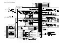 287
287
-
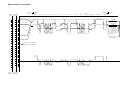 288
288
-
 289
289
-
 290
290


Yamaha LS9 Le manuel du propriétaire
- Catégorie
- Mélangeurs audio
- Taper
- Le manuel du propriétaire
dans d''autres langues
- italiano: Yamaha LS9 Manuale del proprietario
- English: Yamaha LS9 Owner's manual
- español: Yamaha LS9 El manual del propietario
- Deutsch: Yamaha LS9 Bedienungsanleitung
- русский: Yamaha LS9 Инструкция по применению
- Nederlands: Yamaha LS9 de handleiding
- português: Yamaha LS9 Manual do proprietário
- dansk: Yamaha LS9 Brugervejledning
- polski: Yamaha LS9 Instrukcja obsługi
- čeština: Yamaha LS9 Návod k obsluze
- svenska: Yamaha LS9 Bruksanvisning
- Türkçe: Yamaha LS9 El kitabı
- suomi: Yamaha LS9 Omistajan opas
- română: Yamaha LS9 Manualul proprietarului
Documents connexes
-
Yamaha V6 Mode d'emploi
-
Yamaha V5 Mode d'emploi
-
-
-
Yamaha V1 Le manuel du propriétaire
-
Yamaha CL5 Le manuel du propriétaire
-
Yamaha V3 Le manuel du propriétaire
-
Yamaha V2 Manuel utilisateur
-
-