
French version is available for download from the Vogelzang website: http://www.usstove.com/
Version française est disponible pour téléchargement à partir du site Vogelzang: http://www.usstove.com
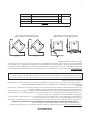
MODEL: VG5770/VG5770i
852050F-1104H
• Please read this entire manual before installation and use of this appliance. Failure to follow
these instructions could result in property damage, bodily injury, or even death.
• Contact your local building or re ofcials about obtaining permits, restrictions and installation
inspection requirements in your area.
• Save these instructions.
U.S. Stove Company
227 Industrial Park Road, South Pittsburg, TN 37380
FOR TECHNICAL ASSISTANCE: Phone 800-750-2723 www.usstove.com
This unit is not intended to be used as a primary source of heat.
Certied for installations in the
USA and Canada.
1
1
2
2
3
3
4
4
A A
B B
TOLERANCES
EXCEPT
AS
NOTED
HOLES
.005"
DECIMAL
.XX = 0.03 XXX = 0.010
ANGULAR
2
DESCRIPTION
FINISH
REFERENCE
SCALE
DWN BY
DATE
SIZE
REV
TITLE NUMBER
UNITED STATES STOVE COMPANY
ESTABLISHED 1869
AB
WHO
2/8/2013
1
OF 1
SHEET
© 2010 United States Stove Company
ALL RIGHTS RESERVED
THE DATA CONTAINED HEREIN IS PROPRIETARY TO U. S.
STOVE COMPANY. THIS DATA SHALL NOT BE DUPLICATED,
TRANSFERRED, MADE AVAILABLE, OR USED BY ANY THIRD
PARTY FOR ANY PURPOSE EXCEPT SPECIFICALLY
AUTHORIZED IN WRITING BY U. S. STOVE COMPANY.
GENERAL NOTES:
ALL FORMED DIMENSIONS ARE TO
THE OUTSIDE OF THE PART,
UNLESS SPECIFIED OTHERWISE.
REVISION HISTORY
REV DESCRIPTION DATE BY
A INITIAL RELEASE
Date
Who?
U.S. Environmental Protection Agency
Certied to comply with 2020 particulate
emission standards using wood pellets.

2
This manual describes the installation and operation of the Vogelzang, VG5770, VG5770I wood heater. This heater
meets the 2015 US Environmental Protection Agency’s wood pellet emissions limits for wood heaters sold after May
15, 2020. Under specic test conditions this heater has been shown to deliver heat at rates ranging from 11,985 to
24,769 Btu/hr.
• IMPORTANT: Read this entire manual before
installing and operating this product. Failure to do
so may result in property damage, bodily injury, or
even death. Proper installation of this stove is crucial
for safe and efcient operation.
• Install vent at clearances specied by the vent
manufacturer.
• Do not connect the pellet vent to a vent serving any
other appliance or stove.
• Do not install a ue damper in the exhaust venting
system of this unit.
• Use of outside air is not required for this unit.
• Contact your local building ofcials to obtain a
permit and information on any additional installation
restrictions or inspection requirements in your area.
• Do not throw this manual away. This manual has
important operating and maintenance instructions
that you will need at a later time. Always follow the
instructions in this manual.
• This appliance is designed for the use of pelletized
fuel that meet or exceed the standard set by the
Pellet Fuel Institute(PFI), The use of other fuels will
void warranty.
• Never use gasoline, gasoline-type lantern fuel,
kerosene, charcoal lighter uid, or similar liquids to
start or ’freshen up’ a re in this stove. Keep all such
liquids well away from the stove while it is in use.
• A working smoke detector must be installed in the
same room as this product.
• Install a smoke detector on each oor of your home;
incase of accidental re from any cause it can
provide time for escape.
• The smoke detector must be installed at least 15
feet (4,57 M) from the appliance in order to prevent
undue triggering of the detector when reloading.
• Do not unplug the stove if you suspect a
malfunction. Turn the ON/OFF SWITCH to ”OFF’ and
contact your dealer.
• Your stove requires periodic maintenance and
cleaning (see ”MAINTENANCE ”). Failure to maintain
your stove may lead to improper and/or unsafe
operation.
• Disconnect the power cord before performing any
maintenance! NOTE: Turning the ON/OFF Switch
to ”OFF” does not disconnect all power to the
electrical components of the stove.
• Never try to repair or replace any part of the stove
unless instructions for doing so are given in this
manual. All other work should be done by a trained
technician.
• Do not operate your stove with the viewing door
open. The auger will not feed pellets under these
circumstances and a safety concern may arise from
sparks or fumes entering the room.
• Allow the stove to cool before performing any
maintenance or cleaning. Ashes must be disposed
in a metal container with a tight tting lid. The
closed container of ashes should be placed on a
non-combustible surface or on the ground, well
away from all combustible materials, pending nal
disposal.
• The exhaust system should be checked monthly
during the burning season for any build-up of soot or
creosote.
• Do not touch the hot surfaces of the stove. Educate
all children on the dangers of a high-temperature
stove. Young children should be supervised when
they are in the same room as the stove.
• The hopper and stove top will be hot during
operation; therefore, you should always use some
type of hand protection when refueling your stove.
• A power surge protector is required. This unit must
be plugged into a 110 - 120V, 60 Hz grounded
electrical outlet. Do not use an adapter plug or
sever the grounding plug. Do not route the electrical
cord underneath, in front of, or over the heater. Do
not route the cord in foot trafc areas or pinch the
cord under furniture.
• The heater will not operate during a power outage.
If a power outage does occur, check the heater for
smoke spillage and open a window if any smoke
spills into the room.
• The feed door must be closed and sealed during
operation.
• Never block free airow through the open vents of
the unit.
• Keep foreign objects out of the hopper.
• The moving parts of this stove are propelled by high
torque electric motors. Keep all body parts away
from the auger while the stove is plugged into an
electrical outlet. These moving parts may begin to
move at any time while the stove is plugged in.
• Do not place clothing or other ammable items on
or near this stove.
• When installed in a mobile home, the stove must
be grounded directly to the steel chassis and
bolted to the oor. WARNING—THIS UNIT MUST
NOT BE INSTALLED IN THE BEDROOM (per HUD
requirements). CAUTION—The structural integrity of
the mobile home oor, wall, and ceiling/roof must
be maintained.
• This appliance is not intended for commercial use.
• CAUTION: Burning fuel creates carbon monoxide
and can be hazardous to your health if not properly
vented.
* This appliance is a freestanding heater. It is not intended to be attached to any type of ducting. It is not a
furnace.
Safety Precautions

3
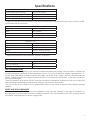
Specications
Heating Specications
Fuel Burn Rate* (lowest setting) 1.5 lbs./hr. (0.5 kg/hr)
Burn Time (lowest setting) 40 hrs. (approximate)
Hopper Capacity 60 lbs. (27kg)
BTU up to 48,000
Fireplace Insert
Height 24” (With Flashing: 32”)
Width 22” (With Flashing: 44”)
Depth 8.5”
Weight 182.5 Lbs. (Flashing 15.5 Lbs)
Flue Size 3” to 4”
Electrical Specications
Electrical Rating 110-120 volts, 60 HZ, 3.0 Amps
Watts (operational) 180
Watts (igniter running) 346
Dimensions
Height 44.5 in. (1130mm)
Width 23 in. (584mm)
Depth 23.5 in. (597mm)
Weight 245 lbs. (111.1kg)
* Pellet size may effect the actual rate of fuel feed and burn times. Fuel feed rates may vary by as much as 20%.
Use PFI listed fuel for best results.
* Approved installations: zer0-clearance, masonry, as a built-in.
FUEL CONSIDERATIONS
Your pellet stove is designed to burn premium hardwood pellets that comply with Association of Pellet Fuel
Industries standards. (Minimum of 40 lbs density per cubic ft, 1/4” to 5/16” diameter, length no greater than 1.5”,
not less than 8,200 BTU/lb, moisture under 8% by weight, ash under 1% by weight, and salt under 300 parts per
million). Pellets that are soft, contain excessive amounts of loose sawdust, have been, or are wet, will result in
reduced performance.
Store your pellets in a dry place. DO NOT store the fuel within the installation clearances of the unit or within the
space required for refueling and ash removal. Doing so could result in a house re.
Do not over re or use volatile fuels or combustibles, doing so may cause a personal and property damage
hazards.
SAFETY AND EPA COMPLIANCE
Your pellet stove has been approved for installation in the USA and Canada. It may also be installed in a
manufactured or mobile home. Your stove certied to ASTM E 1509, and Certied to ULC S627, and(UM) 84-HUD
by INTERTEK Testing Services in Fairview, Oregon USA.

4
INSTALLATION OPTIONS
• Read this entire manual before you install and use your pellet stove. Failure to follow instructions may result in
property damage, bodily injury, or even death!
(See specic installation details for clearances and other installation requirements)
A Freestanding Unit—supported by pedestal/legs and placed on a non-combustible oor surface in compliance
with clearance requirements for a freestanding stove installation.
An Alcove Unit—supported by pedestal/legs and placed on a non-combustible oor surface in compliance
with clearance requirements for an alcove installation.
An Insert Unit— is inserted directly into an existing re place.
Your pellet stove may be installed to code in either a conventional or mobile home (see SPECIAL MOBILE HOME
REQUIREMENTS). The installation must comply with the Manufactured Home and Safety Standard (HUD), CFR3280,
Part 24. It is recommended that only a authorized technician install your pellet stove, preferably an NFI certied
specialist. DO NOT CONNECT THIS UNIT TO ANY AIR DISTRIBUTION DUCT OR SYSTEM.
The use of other components other than stated herein could cause bodily harm, heater damage, and void your
warranty.
IMPROPER INSTALLATION: The manufacturer will not be held responsible for damage caused by the
malfunction of a stove due to improper venting or installation. Call (800) 750-2723 and/or consult a
professional installer if you have any questions.
Installation
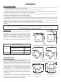
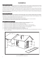
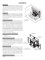
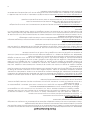
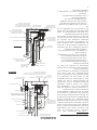
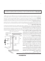
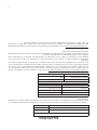
CLEARANCES
Your pellet stove has been tested and listed for
installation in residential, mobile home, and alcove
applications in accordance with the clearances given
in FIGURES 1-2 and TABLE 1. For safety reasons, please
adhere to the installation clearances and restrictions.
Any reduction in clearance to combustibles may only
be done by means approved by a regulatory authority.
FIGURE 1
SIDEWALL CLEARANCES PARALLEL INSTALLATION
FIGURE 2
SIDEWALL CLEARANCES CORNER INSTALLATION
TABLE 1 CLEARANCES
PARALLEL
A - Backwall to unit 3.00 / 76mm
B - Sidewall to ue
11.00 /
280mm
C - Sidewall to top edge of
unit
8.00 / 203mm
CORNER D - Adjacent wall to unit 8.00 / 203mm
U.S. 6.00
Canada 450mm (18”)
U.S. 6.00
Canada 450mm (18”)
U.S. 6.00
Canada
203mm (8”)
U.S. 6.00
Canada
203mm (8”)
U.S. 6.00
Canada
203mm (8”)
U.S. 6.00
Canada
203mm (8”)
U.S. 6.00
Canada 450mm (18”)
U.S. 6.00
Canada 450mm (18”)
U.S. 6.00
Canada
203mm (8”)
U.S. 6.00
Canada
203mm (8”)
U.S. 6.00
Canada
203mm (8”)
U.S. 6.00
Canada
203mm (8”)
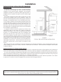
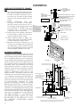
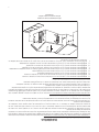
FLOOR PROTECTION
This heater must have a non-combustible oor protector
(UL1618 ember protection) installed beneath it if the
oor is of combustible material. The oor pad or non-
combustible surface should be large enough to cover
at least the area under the product and 6 in. (152 mm)
beyond the front and beyond each side of the fuel
loading and ash removal openings. Your heater will need
a minimum 31” X 38” oor protector. Floor protection
must extend under and 2 in. (50.8 mm) to each side of
the chimney tee for an interior vertical installation (see
FIGURE 4) This applies to both freestanding heaters and
insert heaters.
Canadian Installations require a minimum of 475 mm
[18”] beyond the front of the unit and 203 mm [8”]
beyond each side of the unit. A Floor Protector of 1/4
inch thick is recommended for this installation.
FIGURE 3
THROUGH THE WALL
INSTALLATION
FIGURE 4
INTERIOR VERTICAL
INSTALLATION

5
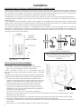
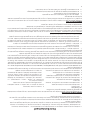
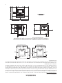
Installation
The minimum installation dimensions, of the insert opening, are:
22” (558.8 mm) wide x 24” (609.6 mm) high x 9.17” (233 mm) deep.
43.93
31.92
5.72
9.17
14.59
28.17
23.60
11.00
43.93
31.92
5.72
9.17
14.59
28.17
23.60
11.00
43.93
31.92
5.72
9.17
14.59
28.17
23.60
11.00
FIGURE 5
INSERT DIMENSIONS
IMPORTANT! This unit is equipped with a negative draft system that pulls air through the burn pot and pushes
the exhaust out of the dwelling. If this unit is connected to a ue system other than the way explained in this
manual, it will not function properly.
MAXIMUM VENTING DISTANCE
Installation MUST include at least 3-feet of vertical pipe outside the home. This will create some natural draft to
reduce the possibility of smoke or odor during appliance shutdown and keep exhaust from causing a nuisance
or hazard by exposing people or shrubs to high temperatures. The maximum recommend vertical venting height
is 12-feet for 3-inch type “PL” vent. Total length of horizontal vent must not exceed 4-feet. This could cause back
pressure. Use no more than 180 degrees of elbows (two 90-degree elbows, or two 45-degree and one 90-degree
elbow, etc.) to maintain adequate draft.
IMPORTANCE OF PROPER DRAFT
Draft is the force which moves air from the appliance up through the chimney. The amount of draft in your
chimney depends on the length of the chimney, local geography, nearby obstructions and other factors. Too
much draft may cause excessive temperatures in the appliance. Inadequate draft may cause backpufng into
the room and ‘plugging’ of the chimney.
Inadequate draft will cause the appliance to leak smoke into the room through appliance and chimney
connector joints.
An uncontrollable burn or excessive temperature indicates excessive draft.
Take into account the chimney’s location to insure it is not too close to neighbors or in a valley which may cause
unhealthy or nuisance conditions.
PELLET VENT TYPE
A UL listed 3-inch or 4-inch type “PL” pellet vent exhaust system must be used for installation and attached to the
pipe connector provided on the back of the stove (use a 3-inch to 4-inch adapter for 4-inch pipe). Connection
at back of stove must be sealed using Hi-Temp RTV. Use 4-inch vent if the vent height is over 12-feet or if the
installation is over 2,500 feet above sea level.
We recommend the use of Simpson Dura-Vent® or Metal-Fab® pipe (if you use other pipe, consult your local
building codes and/or building inspectors). Do not use Type-B Gas Vent pipe or galvanized pipe with this unit. The
pellet vent pipe is designed to disassemble for cleaning and should be checked several times during the burning
season. Pellet vent pipe is not furnished with the unit and must be purchased separately.
VENTING REQUIREMENTS
• Install vent at clearances specied by the vent manufacturer.
• Do not connect the pellet vent to a vent serving any other appliance or stove.
• Do not install a ue damper in the exhaust venting system of this unit.
The following installation guidelines must be followed to ensure conformity with both the safety listing of this stove
and to local building codes. Do not use makeshift methods or compromise in the installation.

6
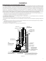
G
FIGURE 6
VENT TERMINATION CLEARANCES
Installation
PELLET VENT INSTALLATION
The installation must include a clean-out tee to enable collection of y ash and to permit periodic cleaning
of the exhaust system. 90-degree elbows accumulate y ash and soot thereby reducing exhaust ow and
performance of the stove. Each elbow or tee reduces draft potential by 30% to 50%.
All joints in the vent system must be fastened by at least 3 screws, and all joints must be sealed with Hi-Temp
RTV silicone sealant to be airtight. The area where the vent pipe penetrates to the exterior of the home must
be sealed with silicone or other means to maintain the vapor barrier between the exterior and the interior of the
home. Vent surfaces can get hot enough to cause burns if touched by children. Noncombustible shielding or
guards may be required.
PELLET VENT TERMINATION
Do not terminate the vent in an enclosed or semi-enclosed area, such as; carport, garage, attic, crawl space,
under a sundeck or porch, narrow walkway, or any other location that can build up a concentration of fumes.
Termination in one of these areas can also lead to unpredictable pressure situations with the appliance, and
could result in improper performance and/or malfunction
The termination must exhaust above the outside air inlet elevation.
The termination must not be located where it will become plugged by snow or other materials.
Do not terminate the venting into an existing steel or masonry chimney.
VENT TERMINATION CLEARANCES
A. Minimum 4-foot (1.22m) clearance below or beside any door or window that opens.
B. Minimum 1-foot (0.3m) clearance above any door or window that opens.
C. Minimum 3-foot (0.91m) clearance from any adjacent building.
D. Minimum 7-foot (2.13m) clearance from any grade when adjacent to public walkways.
E. Minimum 2-foot (0.61m) clearance above any grass, plants, or other combustible materials.
F. Minimum 3-foot (0.91m) clearance from an forced air intake of any appliance.
G. Minimum 2-foot (0.61m) clearance below eves or overhang.
H. Minimum 1-foot (0.3m) clearance horizontally from combustible wall.
I. Must be a minimum of 3 foot (0.91m) above the roof and 2 foot (0.61m) above the highest point or the roof
within 10 feet (3.05m).

7
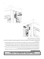
THROUGH THE WALL INSTALLATION (RECOMMENDED
INSTALLATION)
Canadian installations must conform to CAN/CSA-B365.
To vent the unit through the wall, connect the pipe
adapter to the exhaust motor adapter. If the exhaust
adapter is at least 18 in.(457mm) above ground level, a
straight section of pellet vent pipe can be used through
the wall.
Your heater dealer should be able to provide you with
a kit that will handle most of this installation, which will
include a wall thimble that will allow the proper clearance
through a combustible wall. Once outside the structure,
a 3 in.(76mm) clearance should be maintained from the
outside wall and a clean out tee should be placed on
the pipe with a 90-degree turn away from the house. At
this point, a 3ft (0.91m) (minimum) section of pipe should
be added with a horizontal cap, which would complete
the installation (see FIGURE 7).
A support bracket should be placed just below the
termination cap or one every 4ft (1.22m) to make the
system more stable. If you live in an area that has heavy
snowfall, it is recommended that the installation be
taller than 3ft (0.91m) to get above the snowdrift line.
This same installation can be used if your heater is below
ground level by simply adding the clean-out section and
vertical pipe inside until ground level is reached. With this
installation you have to be aware of the snowdrift line,
dead grass, and leaves. We recommend a 3ft (0.91m)
minimum vertical rise on the inside or outside of the
house.
The “through the wall” installation is the least expensive and simplest installation. Never terminate the end vent
under a deck, in an alcove, under a window, or between two windows. We recommend Simpson Dura-Vent®
or Metal-Fab® kits.
THROUGH THE ROOF/CEILING INSTALLATION
When venting the heater through the ceiling, the pipe is connected the same as through the wall, except the
clean-out tee is always on the inside of the house, and a 3 in.(76mm) adapter is added before the clean-out tee.
You must use the proper ceiling support anges and roof ashing (supplied by the pipe manufacturer; follow the
pipe manufacturer’s directions). It is important to note that if your vertical run of pipe is more than 12ft (3.7m), the
pellet vent pipe size should be increased to 4 in. (102mm) in diameter.
Do not exceed more than 4ft (1.22m) of pipe on a horizontal run and use as few elbows as possible. If an offset
is required, it is better to install 45-degree elbows rather than 90-degree elbows.
FIGURE 7
TYPICAL THROUGH THE WALL INSTALLATION
Installation
ATTENTION: DO NOT vent under any porch, deck, awning, or in any semi enclosed or roofed area. Doing so
may result in unpredictable airow at the vent cap under certain conditions and can affect the performance
of your stove, as well as, other unforeseeable issues.

8
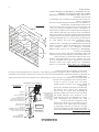
SPECIAL MOBILE HOME REQUIREMENTS
• WARNING! - Do not install in a sleeping room
• CAUTION! - The structural integrity of the mobile home
oor, wall, and ceiling/roof must be maintained.
NOTE: Installation should be in accordance with the
Manufactured Home and Safety Standard (HUD), CFR 3280,
Part 24.
In addition to the previously detailed installation requirements,
mobile home installations must meet the following requirements:
• This stove must be securely fastened to the oor of the
mobile home through the two holes in the rear of the stove
using 2, ¼” lag bolts that are long enough to go through
both a hearth pad, if used, and the oor of the home.
• The heater must be electrically grounded to the steel
chassis of the mobile home with 8 GA copper wire using
a serrated or star washer to penetrate paint or protective
coating to ensure grounding.
• Vent must be 3 or 4-inch “PL” Vent and must extend a
minimum or 36 in.(914mm) above the roof line of the mobile home and must be installed using a UL listed
ceiling re stop and rain cap.
• When moving your mobile home, all exterior venting must be removed while the mobile home is being
relocated. After relocation, all venting must be reinstalled and securely fastened.
• Outside Air is mandatory for mobile home installation. See Outside Air Supply section and your dealer for
purchasing.
• Check with your local building ofcials as other codes may apply.
NOTE: Dimensions from the oor to your
stoves inlet/exhaust pipes are approximate
and may vary depending on your
installation.
FIGURE 9
TYPICAL FRESH AIR TERMINATION
FIGURE 8
EXHAUST/
INLET LOCATIONS
OUTSIDE AIR SUPPLY (OPTIONAL, UNLESS INSTALLING IN A MOBILE HOME)
Adequate ventilation air is required to operate this heater. During operation, the heater draws air for combustion
which can be assisted by the installation of outside combustion air inlets. However, certain weather conditions
such as icing or use of kitchen exhaust fans may impact and reduce the effectiveness of vents. It is important to
note that room air starvation will negatively impact the operation of the heater.
Depending on your location and home construction, outside air may be necessary for optimal performance.
Metal pipe (solid or exible) must be used for the outside air installation. PVC pipe is NOT approved and should
NEVER be used.
A wind shield over the termination of the outside air pipe or a 90-degree elbow or bend away from the prevailing
winds MUST be used when an outside air pipe is installed through the side of a building. The outside air termination
MUST be at least 1ft (0.305m) away from the exhaust system termination.
The outside air pipe on your heater is 2” (50.8mm) OD. The outside air connecting pipe must be at least 2”
(50.8mm) ID. The outside air connection used MUST NOT restrict the amount of air available to your heater. The
outside air connecting pipe must be as short and free of bends as possible, and it must t over, not inside, the
outside air connection to the heater.
Installation
FIGURE 10
MOBILE HOME
MOUNTING BOLT HOLES

9
Installation
PREPARATION
Factory packaging must be removed, and some minor
assembly work is required prior to installation. Access
to the rear of the stove is necessary. The circuit board/
control panel must be unpacked and installed in the side
ashing on the insert or side panel on the freestanding.
(See installation instructions provided with the circuit
board)
CLEARANCES
This Insert is approved for installation into code complying
masonry replaces. It is also approved for use in listed
factory built replaces (UL 127) and standard residential
built-ins, including Mobile Home built-in installations, of
the following description: all brands at least 34” wide
and 20 ½” high.
COMBUSTION AIR SUPPLY
If outdoor combustion air is supplied the heater must be
attached to the structure. For a mobile home installation
the stove must be connected to an outside source of
combustion air. A 2” inside diameter metallic pipe, either
exible or rigid, may be attached to the inlet at the stove’s
rear. A rodent guard (minimum ¼” wire mesh)/wind
hood must be used at the terminus. All connections must
be secured and airtight by either using the appropriately
sized hose clamp and/or UL-181-AP foil tape. For mobile
home installations only: 2” inside diameter pipe may be
used for the rst 5 feet of combustion air supply run. From
5 to 10 feet use 2 ¾” inside diameter pipe. No combustion
air supply may exceed 10 feet.
SOURCES OF OUTSIDE COMBUSTION AIR
In replaces
• Chimney top.
• Ash clean out door.
WHEN OUTSIDE AIR IS NOT USED
If outside air is not used, it is important that combustion
air is easily available to the air inlet. A closeable outside
air register can be used in tightly insulated homes. In
insert installations, ashing vents should not be restricted.
The ashing should not necessarily seal the replace
face. DO NOT CONNECT THIS UNIT TO A CHIMNEY FLUE
SERVING ANOTHER APPLIANCE.
INSERT INSTALLATIONS
Insert installations must be vented with 3” or 4” pipe.
Pipe may be single wall stainless steel exible pipe. Vent
may terminate within chimney beyond a blanking plate
or extend to the chimney top. See “COMBUSTION AIR
SUPPLY” for outside air access information. The replace
and chimney should be cleaned thoroughly before
starting the installation. We suggest painting the interior
of particularly old and dirty replaces to seal any odors.
ASSEMBLING THE FLASHING SET
Follow the instructions packaged with this stoves
Flashing.
COMBUSTIBLE WALL
MANTLE
6”
UP TO
12”
12”
8.25”
6”
10”
NONCOMBUSTIBLE HEARTH
HEARTH EXTENSION
COMBUSTIBLE FLOOR
TOP
FACING
SIDE
FACING
FIGURE 11
CLEARNACES
LEFT SIDE TOP
SURROUND PANEL
RIGHT SIDE
TOP SURROUND PANEL
LEFT SIDE
SURROUND PANEL
RIGHT SIDE
SURROUND PANEL
CIRCUIT BOARD
FIGURE 12
INSERT INSTALLATION

10
WHEN VENT PIPE EXTENDS TO CHIMNEY
TOP
10. You will need a pipe length equal to
the chimney height (from hearth) plus
6 inches. If outside combustion air is to
be used, you will need a pipe length
equal to the chimney height plus 12
inches.
11. Attach cerablanket wrap (not
included) to the end of vent pipe
that will connect to the stove. Use 12-
inch lengths of light gauge metal wire
(not included) or metallic tape (not
included). This is to protect interior
components from excess heat.
12. Set the insert on the hearth and slide it
in far enough to attach the vent pipe
(and combustion pipe if used).
13. Attach ashing (refer to Figure 13),
route power cord out the side nearest
a 120V receptacle. Slide in insert.
14. Measure and build chimney top. Cut
out hole for vent pipe (and combustion
air intake pipe, if used). Install and seal
with a non-hardening mastic to prevent
water leakage. Install the vent cap.
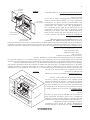
AS A BUILT-IN FIREPLACE
The gures on this page describe this stoves
installation vented into either a special chase
built outside an outer wall or a false inside wall.
This is especially suited for new construction
or remodeling. The equipment compartment
(sides and rear of the stove in replace) must
be enclosed per the applicable electrical
standards. NOTE: Floor protection for Built-in
raised hearths requires a continuous sheet
beneath to prevent the possibility of embers
falling through to the combustible oor if
cracks or separation should occur in the
nished surface. This replace insert must be
installed with a continuous chimney liner of 3”
or 4” diameter extending from the replace
insert to the top of the chimney. The chimney
liner must conform to the Class 3 requirements
of CAN/ULC-S635, Standard for Lining
Systems for Extending Masonry or Factory-
Built Chimneys and Vents, or CAN/ULC-S640,
Standard for Lining Systems for New Masonry
Chimneys. The existing replace damper may
be removed or locked into the open position.
The chase dimensions shown are minimums
and must be maintained. IF THE FIREPLACE
HAS BEEN MODIFIED TO ACCOMMODATE
THE FIREPLACE INSERT A METAL TAG SHALL
BE ATTACHED TO THE FIREPLACE. DO NOT
USE MAKESHIFT COMPROMISES DURING
INSTALLATION.
Installation
6”
6”
MAX
15”
12”
3”
TOP PLATE
(SEAL TO CHIMNEY TOP
WITH NON-HARDENING
MASTIC)
NOTE:
FOLLOW METAL
CHIMNEY INSTALLATION
INSTRUCTIONS
BLANKING PLATE (SEAL WITH
NON-HARDENING MASTIC).
OPTIONAL COMBUSTION AIR INTAKE
(EXTENDS THROUGH DHIMNEY TOP WITH
180 DEG. BEND) REQUIRED IN MOBILE
HOME AND ZERO-CLEARANCE FIREPLACES.
NOT RECOMMENDED IN MASONRY
FIREPLACES OR BUILT IN INSTALLATIONS.
LEVELING BOLTS
EXHAUST PIPE INSTALLATION
HEARTH
NOTE:
FOLLOW METAL
CHIMNEY INSTALLATION
INSTRUCTIONS
TOP PLATE
(SEAL TO CHIMNEY TOP
WITH NON-HARDENING
MASTIC)
EXTENSION TO CHIMNEY T
OP OPTIONAL.
(REQUIRED IN MOBILE HOME AND ZERO-
CLEARANCE FIREPLACES.
RECOMMENDED IN ALL FIREPLACES).
3 OR 4 INCH STAINLESS STEEL
SINGLE WALL PIPE.
BLANKING PLATE (SEAL WITH
NON-HARDENING MASTIC).
CHIMNEY NEED ONLY EXTEND
12” ABOVE BLANKING PLATE.
3 OR 4 INCH STAINLESS STEEL
FLEX PIPE.
FIREPLACE INSERT
SIDE ELEVATION
1” CERIBLANKET
NOTE:
WHEN MANTLE EXTENDS
MORE THAN 6” FROM
FIREPLACE FACE, A 15”
MINIMUM DIMENSION
MUST BE MAINTAINED
FROM STOVE TOP TO
BOTTOM OF MANTLE.
OUTSIDE COMBUSTION AIR INSTALLATION
HEARTH
FIGURE 13
EXHAUST PIPE
INSTALLATION
23.75 min”
8”
MIN
MANTLE
FACADE
OPENING
214.15” min
20.”12 min.
46” MIN
RAISED HEARTH
FIGURE 14
SEE “INSERT INSTALLATIONS” FOR
PANEL SURROUND INSTALLATION
6”
MIN.
6”
MIN.
3”
MIN.
3”
MIN.
LISTED
CHIMNEY
CAP
STORM
COLLAR
CHASE CAP
MANTLE
12”
FACING
6”
MAX
10”
THE PANEL SURROUND KIT
D)
ATTACH THE PANEL SURROUND
TO THE PANEL SURROUND TO
THE FACE OF THE FIREPLACE
WITH ONE SCREW.
2.25”
23.75”
6”
MIN.
8”
MIN.
FLOOR PROTECTOR MUST BE
CONTINUOUS WITH NO JOINTS
RAISED HEARTH MUST BE BUILT
OF 8” HOLLOW CONCRETE BLOCKS.
IF CHOOSING TO VENT HORIZONTALLY THROUGH THE WALL, WE RECOMMEND
TERMINATING VERTICALLY WITH AN ADDITIONAL RUN OF AT LEAST 5 FEET.
*
MAY BE DRAWN FROM
ATED CRAWL SPACE.
OUTSIDE AIR
LISTED
CHIMNEY
CAP
*
LISTED
THIMBLE
6”
15.75”
EQUIPMENT
COMPARTMENT
(OPTIONAL VERTICAL INSTALLATION)
L-VENT ONLY
SIDING
5/8” SHEETROCK
(ENTIRE FACADE)
A 1/4” (OR SMALLER) WIRE MESH
SCREEN MUST BE INSTALLED IN
THIS INSTALLATION TO COVER
THE EQUIPMENT COMPARTMENT.
FIGURE 15

11
Installation
INSTALLATION IN TO A FACTORY BUILT (METAL) FIREPLACE
When installing into a factory built replace, the rebox must accept the insert without modication other
than removing bolted or screwed together pieces such as smoke shelf/deectors, ash lips, screen or door tracks
and damper assemblies. These items must be reinstalled to restore the replace to its original operating condition
if the insert is removed and not replaced. The removal of any part must not alter the integrity of the listed replace
in any way. The factory built replace must be listed per UL 127. Installation must include a full height listed
chimney liner meeting type HT requirements (2100o F) per 1777 (U.S.). The liner must be securely attached to the
insert ue collar and the chimney top. The damper area must be sealed to prevent room air passage to chimney
cavity. Alteration of the replace in any manner is not permitted except with the following exceptions:
• External trim pieces, which do not affect the operation of the replace, may be removed proving they can
be stored on or within, the replace for re-assembly if the insert is removed.
• The replace damper may be removed to install the chimney liner.
Circulating air chambers, louvers or cooling air inlet or outlet ports (i.e. in a steel replace liner or metal heat
circulator) shall not be blocked.
Means must be provided for removal of the insert to clean the chimney ue.
A permanent metal warning label must be attached to the back wall of the replace opening stating the
following:
• “This replace has been altered to accommodate a replace insert and should be inspected by a qualied
person prior to re-use as a conventional replace.”
• This label is available upon request.
Final approval is contingent on the authority having jurisdiction.
VERTICAL CAP
STORM COLLAR
COVER PLATE
(NON-COMBUSTIBLE)
SEAL WITH SILICONE.
3 OR 4 INCH L-VENT
OR STAINLESS STEEL
FLEXIBLE OR SINGLE
WALL PIPE
THE SMOKE SHELF
MAY BE REMOVED
10”
THE DAMPER MAY
BE REMOVED
INTERNAL BAFFLES
MAY BE REMOVED
TO PREVENT FIREPLACE
ODORS FROM ENTERING
THE HOME, PAINT THE
INTERIOR OF THE FIREPLACE
WITH LATEX PAINT
THE METAL SIDES, FRAME MEMBERS, OR OTHER
STRUCTURAL COMPONENTS OF THE FACTORY BUILT
FIREPLACE MAY NOT BE REMOVED OR ALTERED
USE THE ZERO-CLEARANCE
SKIRT TO SUPPORT THE
INSERT ON RAISED FIREPLACES
THE MASONRY LINING
MAY NOT BE REMOVED
NOTE:
THE LOG SHELF, SCREEN,
AND DOORS (IF PRESENT)
MUST BE REMOVED
FIGURE 16

12
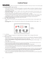
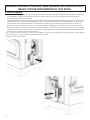
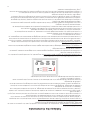
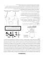
PANEL CONTROLS
The blowers and automatic fuel supply are controlled from a panel on the top of this unit. The control panel
functions are a follows.
A. ON/OFF SWITCH (“POWER” BUTTON)
• When pushed, the stove will automatically ignite. No other re starter is necessary. The igniter will stay on
for at least 10 and up to 12 minutes, depending on when Proof of Fire is reached. The re should start in
approximately 5 minutes.
• The red light located above the “POWER” button will turn green when pressed and remain green until
the stove is turned off.
• After pushing “POWER”, the auger motor is on for 3.5 minutes, off for 1 minute. During the remainder of
the start-up period, the auger motor operates on the heat range “1” setting.
• During start up the heat level advance (Up and Down keys) will change the heat range indicator level
accordingly, but there is no change in the stoves operating conditions until start-up is completed.
• During start-up ignition must occur within 12 minutes or the stove will error out and show E4.
• During the start-up phase, the Mode key does not function.
B. LEVEL / TEMP ARROW BUTTONS
• These buttons when pushed will set the pellet feed rate, hence the heat output or heat range of your
stove.
• The levels of heat output will incrementally change on the bar graph starting from heat range “1” to
heat range “5”.
Control Panel
C. °C / °F Button
• The °C / °F button changes the two digit display from degrees Celsius to degrees Fahrenheit.
D. MODE (M/T) BUTTON
• The Mode of the stove can be switched between manual and controlled with a Thermostat. Separate
LEDs to the left of the two digit display indicate the mode of operation – Manual or T-Stat. The stove has
to be in normal operation to be switched from Manual to T-Stat mode.
• Manual mode operates according to the 5 set levels of feed on the bar graph from heat range “1” to
heat range “5”.
• T-Stat mode works as follows:
• The stove has a built in Thermostat into the controls of the appliance. The temperature sensor for the
T-Stat is located on the back of the stove behind the display board.
• Once the stove has gone into run mode the stove can be switch into T-Stat mode.
• The Up and Down Level / Temp Arrow buttons are used to change the desired set-point temperature.
Once the desired temperature is reached the two digit display will ash for four seconds and reset to
the actual room temperature.
• Once the stove reaches within 3°F of the desired temperature set point, it returns to the heat range that
the stove was set on before it was switched to T-Stat mode (if the stove was running on heat range “5”
when switched to T-stat mode when it gets within 3°F of the set point it will return to heat range “5”).
• Once the stove reaches the desired set-point, the stove will drop to heat range “1”.
• When room temperature drops below desired set-point the stove will ramp back up until it reaches the
desired temperature.
Level / Temp
Manual
T-Stat
FIGURE 17
CONTROLS

13
Operation
• DO NOT USE CHEMICALS OR FLUIDS TO START THE FIRE - Never use gasoline, gasoline-type lantern fuel,
kerosene, charcoal lighter uid, or similar liquids to start or “freshen up” a re in this stove. Keep all such
liquids well away from the stove while it is in use.
• HOT WHILE IN OPERATION. KEEP CHILDREN, CLOTHING AND FURNITURE AWAY. CONTACT MAY CAUSE SKIN
BURNS.
This heater is designed to burn only PFI Premium grade pellets. This appliance can also burn pellets rated as
standard after May 16, 2015.
DO NOT BURN:
1. Garbage;
2. Lawn clippings or yard waste;
3. Materials containing rubber, including tires;
4. Materials containing plastic;
5. Waste petroleum products, paints or paint thinners,
or asphalt products;
6. Materials containing asbestos;
7. Construction or demolition debris;
8. Railroad ties or pressure-treated wood;
9. Manure or animal remains;
10. Salt water driftwood or other previously salt water
saturated materials;
11. Unseasoned wood; or
12. Paper products, cardboard, plywood, or
particleboard. The prohibition against burning
these materials does not prohibit the use of re
starters made from paper, cardboard, saw dust,
wax and similar substances for the purpose of
starting a re in an affected wood heater.
Burning these materials may result in release of toxic fumes or render the heater ineffective and cause smoke.
PROPER FUEL
THIS STOVE IS APPROVED FOR BURNING PELLETIZED WOOD FUEL ONLY ! Factory-approved pellets are those 1/4”
or 5/16” in diameter and not over 1” long. Longer or thicker pellets sometimes bridge the auger ights, which
prevents proper pellet feed. Burning wood in forms other than pellets is not permitted. It will violate the building
codes for which the stove has been approved and will void all warranties. The design incorporates automatic
feed of the pellet fuel into the re at a carefully prescribed rate. Any additional fuel introduced by hand will not
increase heat output but may seriously impair the stoves performance by generating considerable smoke. Do
not burn wet pellets. The stove’s performance depends heavily on the quality of your pellet fuel. Avoid pellet
brands that display these characteristics:
1. Excess Fines – “Fines” is a term describing crushed pellets or loose material that looks like sawdust or sand.
Pellets can be screened before being placed in hopper to remove most nes.
2. Binders – Some pellets are produced with materials to hold the together, or “bind” them.
3. High ash content – Poor quality pellets will often create smoke and dirty glass. They will create a need for
more frequent maintenance. You will have to empty the burn pot plus vacuum the entire system more often.
Poor quality pellets could damage the auger. We cannot accept responsibility for damage due to poor
quality pellet.
PRE-START-UP CHECK
Remove burn pot, making sure it is clean and none of the air holes are plugged. Clean the rebox, and then
reinstall burn pot. Clean door glass if necessary (a dry cloth or paper towel is usually sufcient). Never use abrasive
cleaners on the glass or door. Check fuel in the hopper, and rell if necessary.
NOTE: The hopper can hold up to 60 lbs. of pellets.
BUILDING A FIRE
Never use a grate or other means of supporting the fuel. Use only the burn pot supplied with this heater.
Hopper lid must be closed in order for the unit to feed pellets.
During the start-up period:
1. Make sure burn pot is free of pellets.
2. DO NOT open the viewing door.
3. DO NOT open the damper, the damper needs to be closed during start up.
4. DO NOT add pellets to the burn pot by hand.
NOTE: During the rst few res, your stove will emit an odor as the high temperature paint cures or becomes
seasoned to the metal. Maintaining smaller res will minimize this. Avoid placing items on stove top during this
period because paint could be affected.
Attempts to achieve heat output rates that exceed heater design specications can result in permanent
damage to the heater.

14
Operation
AUTOMATIC IGNITOR
Fill hopper and clean burn pot.
1. Press “On/Off” button. Make sure green light comes on.
2. The damper should be completely closed or open no more than ¼ of the way during start-up. This will vary
depending on your installation and elevation. Once re is established adjust for desired ame increasing the
amount the damper is open as the heat setting is increased. (See “DAMPER CONTROL”)
3. Adjust feed rate to desired setting by pressing “Heat Level Advance” button.
If re doesn’t start in 12 minutes, press “On/Off”, wait a few minutes, clear the burn pot, and start procedure
again.
DAMPER CONTROL
The damper control lever is located on the back of the stove on the lower left side. The dampener adjusts
the combustion air. This control is necessary due to the varied burn characteristics of individual installations,
different pellet brands and pellet feed rates. It allows you to improve the efciency of your stove. Providing
correct combustion air will reduce the frequency of cleaning your glass door and prevent the rapid buildup of
creosote inside your stove and chimney.
You should adjust the damper based on the re’s appearance. A low, reddish, dirty re can be improved by
turning the dampener slightly to the right. A “blow torch” re can be improved by turning the dampener to the
left a little bit.
As a general rule, on lower feed rate settings, the damper should be farther to the left closing it off. On higher
feed rates, the damper should be open more by having it set more towards the right. Through trial and error, you
will nd the best setting. Consult your dealer if you need help.
NOTE: On heat range “1”, damper should be either completely closed or open no more than a ¼ of the way. If
damper is open to far, it can cause the re to go out.
OPENING DOOR
If the door is opened while the stove is in operation it must be closed within 30 seconds or the stove will shut
down. If the stove shuts down push the “On/Off” button to re-start your stove. The stove will have to fully shut
down and turn off before you will be able to restart the stove.
ROOM AIR FAN
When starting your stove the Room Air Fan will not come on until the stove’s heat exchanger warms up. This
usually takes about 10 minutes from start-up.
IF STOVE RUNS OUT OF PELLETS
The re goes out and the auger motor and blowers will run until the stove cools. This will take 30 minutes or longer
depending on the heat remaining in the appliance. After the stove components stop running all lights on the
display will go out and the two digit display will begin ashing “E3”
REFUELING
• The hopper and stove top will be hot during operation; therefore, you should always use some type of hand
protection when refueling your stove.
• Never place your hand near the auger while the stove is in operation.
We recommend that you not let the hopper drop below ¼ full.
TAMPER WARNING
This wood heater has a manufacturer-set minimum low burn rate that must not be altered. It is against federal
regulations to alter this setting or otherwise operate this wood heater in a manner inconsistent with operating
instructions in this manual.

15
KEEP HOPPER LID CLOSED AT ALL TIMES EXCEPT WHEN REFILLING.
DO NOT OVERFILL HOPPER.
SHUTDOWN PROCEDURE
Turning your stove off is a matter of pressing the “POWER” button on the display board. The green light will turn
back to red when the “POWER” button is pushed. The auger motor will stop, and the blowers will continue to
operate until the internal rebox temperatures have fallen to a preset level.
1. Your stove is equipped with a high temperature thermodisc. This unit has a manual reset thermodisc. This
safety switch has two functions.
A. To recognize an overheat situation in the stove and shut down the fuel feed or auger system.
B. In case of a malfunctioning convection blower, the high-temperature thermodisc will automatically shut
down the auger, preventing the stove from overheating.
NOTE: On some units, once tripped, like a circuit breaker, the reset button will have to be pushed before restarting
your stove. On other units the thermodisc has no reset button and will reset itself once the stove has cooled. The
manufacturer recommends that you call your dealer if this occurs as this may indicate a more serious problem.
A service call may be required.
2. If the combustion blower fails, an air pressure switch will automatically shut down the auger.
NOTE: Opening the stove door for more than 30 seconds during operation will cause enough pressure change to
activate the air switch, shutting the fuel feed off. The stove will shut down and show “E2” on the two digit display.
The stove has to fully shut down before restarting.
Operation
WARNING: Never shut down this unit by unplugging it from the power source.
• Failure to clean and maintain this unit as indicated can result in poor performance, safety hazards, re, and
even death.
• Unplug your stove’s electrical cord prior to removing the back panel or opening the exhaust system for any
inspection, cleaning, or maintenance work.
• Never perform any inspections, cleaning, or maintenance on a hot stove.
• Do not operate stove with broken glass, leakage of ue gas may result.
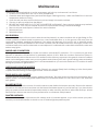
EXHAUST SYSTEM
Creosote Formation – When any wood is burned slowly, it produces tar and other organic vapors, which combine
with expelled moisture to form creosote. The creosote vapors condense in the relatively cool chimney ue or a
newly started re or from a slow-burning re. As a result, creosote residue accumulates on the ue lining. When
ignited, this creosote makes an extremely hot re, which may damage the chimney or even destroy the house.
Despite their high efciency, pellet stoves can accumulate creosote under certain conditions.
Fly Ash – This accumulates in the horizontal portion of an exhaust run. Though non-combustible, it may impede
the normal exhaust ow. It should therefore be periodically removed.
Inspection and Removal – The chimney connector and chimney should be inspected by a qualied person
annually or per ton of pellets to determine if a creosote or y ash build-up has occurred. If creosote has accumulated,
it should be removed to reduce the risk of a chimney re. Inspect the system at the stove connection and at the
chimney top. Cooler surfaces tend to build creosote deposits quicker, so it is important to check the chimney
from the top as well as from the bottom. The creosote should be removed with a brush specically designed for
the type of chimney in use. A qualied chimney sweep can perform this service. It is also recommended that
before each heating season the entire system be professionally inspected, cleaned and, if necessary, repaired.
To clean the chimney, disconnect the vent from the stove.
Maintenance

16
INTERIOR CHAMBERS
• Burn Pot: Periodically remove and clean the burn pot and the area inside the burn pot housing. In particular,
it is advisable to clean out the holes in the burn pot to remove any build up that may prevent air from
moving through the burn pot freely.
• Heat Exchanger: There is a clean out plate on both sides of the heat exchanger that need to be removed to
clean y ash out of the heat exchanger. The clean outs are located inside the cabinet doors, on the lower
front corners of the heat exchanger. It is imperative that they be cleaned out at a minimum of once per
month. To access these clean outs, you must remove both side panels. The clean outs are secured to the
rebox with (2) 5/16” screws. Remove the clean outs and vacuum out any accumulated ash. This should be
done at least once per month or more frequently if large amounts of ash are noticed while cleaning or if the
stove does not seem to be burning properly
If a vacuum is used to clean your stove, we suggest using a vacuum designed for ash removal. Some regular
vacuum cleaner (i.e. shop vacs) may leak ash into the room.
DO NOT VACUUM HOT ASH
WARNING: FAILURE TO PROPERLY MAINTENANCE THE CLEAN OUTS WILL
RESULT IN POOR PERFORMANCE OF THIS STOVE.

17
Maintenance
ASH REMOVAL
Remove the ashes periodically to avoid unnecessary ash build up. Ash removal is as follows:
1. Let re burn out and allow unit cool to room temperature.
2. Clean the heat exchanger tubes (see Heat Exchanger Cleaning section) – Make sure Pellet Stove is at room
temperature before touching .
3. Open the ash pan door, remove the burn pot and empty into metal container.
4. Vacuum to remove ashes from the rebox.
5. BE SURE THAT ASHES ARE COOL TO THE TOUCH BEFORE VACUUMING. Some vacuum cleaners may leak ash
into the room. Your vacuum cleaner should have a special lter or bag to eliminate leakage.
6. Remove ash pan and dispose of ashes into metal container.
7. Reinstall ash pan.
8. Reinstall burn pot.
ASH DISPOSAL
Remove ashes when unit has cooled. Ashes should be placed in a metal container with a tight tting lid. The
closed container of ashes should be placed on a noncombustible oor or on the ground, well away from all
combustible materials, pending nal disposal. If the ashes are disposed of by burial in soil or otherwise locally
dispersed, they should be retained in the closed container until all embers have been thoroughly cooled. The
container shall not be used for other trash or waste disposal. If combined with combustible substances, ashes and
embers may ignite.
SMOKE AND CO MONITORS
Burning wood naturally produces smoke and carbon monoxide(CO) emissions. CO is a poisonous gas when
exposed to elevated concentrations for extended periods of time. While the modern combustion systems in
heaters drastically reduce the amount of CO emitted out the chimney, exposure to the gases in closed or conned
areas can be dangerous. Make sure you stove gaskets and chimney joints are in good working order and sealing
properly to ensure unintended exposure. It is recommended that you use both smoke and CO monitors in areas
having the potential to generate CO.
CHECK AND CLEAN THE HOPPER
Check the hopper periodically to determine if there is any sawdust (nes) that is building up in the feed system
or pellets that are sticking to the hopper surface. Clean as needed.
DOOR AND GLASS GASKETS
Inspect the main door and glass window gaskets periodically. The main door may need to be removed to have
frayed, broken, or compacted gaskets replaced by your authorized dealer. This unit’s door uses a 5/8” diameter
rope gasket.
BLOWER MOTORS
Clean the air holes on the motors of both the exhaust and distribution blowers annually. Remove the exhaust
blower from the exhaust duct and clean out the internal fan blades as part of your fall start-up. If you have indoor
pets your power motors should be inspected monthly to make sure they are free of animal hair build up. Animal
hair build up in blowers can result in poor performance or unforeseen safety hazards.
PAINTED SURFACES
Painted surfaces may be wiped down with a damp cloth. If scratches appear, or you wish to renew your paint,
contact your authorized dealer to obtain a can of suitable high-temperature paint.

18
Maintenance
GLASS - CLEANING, REMOVAL AND REPLACEMENT OF BROKEN DOOR GLASS
Cleaning - We recommend using a high quality glass cleaner. Should a buildup of creosote or carbon accumulate,
you may wish to use 000 steel wool and water to clean the glass. DO NOT use abrasive cleaners. DO NOT perform
the cleaning while the glass is HOT.
In the event you need to replace the glass:
9. Remove the four (4) screws and glass retainers. While wearing leather gloves (or any other gloves suitable for
handling broken glass), carefully remove any loose pieces of glass from the door frame. Dispose of all broken
glass properly. ONLY high temperature ceramic glass of the correct size and thickness may be used. DO NOT
substitute alternative materials for the glass. Contact your authorized dealer to obtain this glass.
10. Re-install the new glass by re-attaching the retainers and screws, be careful not to over tighten the screws
for this could damage the glass.
DO NOT abuse the door glass by striking, slamming or similar trauma. Do not operate the stove with the glass
removed, cracked or broken.
FALL START UP
Prior to starting the rst re of the heating season, check the outside area around the exhaust and air intake
systems for obstructions. Clean and remove any y ash from the exhaust venting system. Clean any screens on
the exhaust system and on the outside air intake pipe. Turn all of the controls on and make sure that they are
working properly. This is also a good time to give the entire stove a good cleaning throughout.
SPRING SHUTDOWN. After the last burn in the spring, remove any remaining pellets from the hopper and the
auger feed system. Scoop out the pellets and then run the auger until the hopper is empty and pellets stop
owing (this can be done by pressing the “ON” button with the viewing door open). Vacuum out the hopper.
Thoroughly clean the burn pot, and rebox. It may be desirable to spray the inside of the cleaned hopper with an
aerosol silicone spray if your stove is in a high humidity area. The exhaust system should be thoroughly cleaned.
SPRING SHUTDOWN
After the last burn in the spring, remove any remaining pellets from the hopper and the auger feed system.
Scoop out the pellets and then run the auger until the hopper is empty and pellets stop owing (this can be done
by pressing the “ON” button with the viewing door open). Vacuum out the hopper. Thoroughly clean the burn
pot, and rebox. It may be desirable to spray the inside of the cleaned hopper with an aerosol silicone spray if
your stove is in a high humidity area. The exhaust system should be thoroughly cleaned.
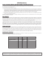
MAINTENANCE SCHEDULE
Use the following as a guide under average use conditions. Gaskets around door and door glass should be
inspected and repaired or replaced when necessary.
Daily Weekly Monthly or as needed
Burn Pot Stirred Empty
Combustion Chamber Brushed
Ashes Check Empty
Interior Chambers Vacuumed
Combustion Blower Blades Vacuumed / Brushed
Convection Blower Impeller Vacuumed / Brushed
Vent System Cleaned
Gaskets Inspected
Glass Wiped Cleaned
Hopper (end of season) Emptied and vacuumed
ATTENTION: This wood heater needs periodic inspection and repair for proper operation. It is against federal
regulations to operate this wood heater in a manner inconsistent with operating instructions in this manual.

19
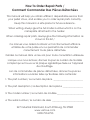
When your stove acts out of the ordinary, the rst reaction is to call for help. This guide may save time and money
by enabling you to solve simple problems yourself. Problems encountered are often the result of only ve factors:
1) poor fuel; 2) poor operation or maintenance; 3) poor installation; 4) component failure; 5) factory defect. You
can usually solve those problems related to 1 and 2. Your dealer can solve problems relating to 3, 4 and 5. Refer
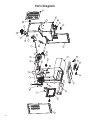
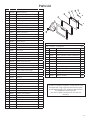
to diagrams on page 25 to help locate indicated parts.
For the sake of troubleshooting and using this guide to assist you, you should look at your heat level setting to
see which light is ashing.
• Disconnect the power cord before performing any maintenance! NOTE: Turning the ON/OFF Switch to ”OFF”
does not disconnect all power to the electrical components of the stove.
• Never try to repair or replace any part of the stove unless instructions for doing so are given in this manual.
All other work should be done by a trained technician.
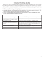
Trouble Shooting Guide
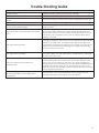
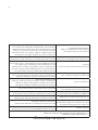
Display is Flashing “E1”
Possible Causes Possible Remedies: (Unplug stove rst when possible)
The convection blower is overheating and
tripping the internal temperature shutoff.
Clean any dust off of the windings and fan blade. If oiling the blower
does not help, the blower may be bad.
The stove is being left on the highest setting for
extended periods of time.
If operating the heater on the highest heat setting, the room
temperature could increase enough and lead to potential overheating
situations. If this happens try operating at a lower heat setting.
Fuel other than wood pellets is being burned in
the stove.
This pellet stove is designed and tested to use wood pellets. Check for
signs of fuel other than wood pellets. No other types of fuel have been
approved for this pellet stove. If there are signs of other types of fuel
being used, stop using them immediately.
Power surge or brown out situation.
A power surge, spike, or voltage drop could cause the high limit switch
to trip. Check to see if a surge protector is being used on the stove. If
not, recommend one to the customer.
High Limit Switch is malfunctioning. If the other items check out OK, replace the high limit switch.

20
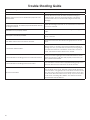
Trouble Shooting Guide
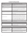
Display is Flashing “E2”
Possible Causes Possible Remedies: (Unplug stove rst when possible)
Airow switch hose or stove attachment pipes for hose
are blocked.
Unhook air hose from the air switch and blow through it.
If air ows freely, the hose and tube are ne. If air will not
ow throw the hose, use a wire coat hanger to clear the
blockage.
The air inlet, burnpot, interior combustion air chambers,
combustion blower, or exhaust pipe are blocked with ash
or foreign material.
Follow all cleaning procedures in the maintenance section of
the owner’s manual.
The rebox is not properly sealed.
Make sure the door is closed and that the gasket is in good
shape.
Vent pipe is incorrectly installed.
Check to make sure vent pipe installation meets criteria in
owner’s manual.
The airow switch wire connections are bad.
Check the connectors that attach the gray wires to the air
switch.
Combustion blower failure.
With the stove on, check to see if the combustion blower is
running. If it is not, you will need to check for power going to
the combustion blower. It should be a full current. If there is
power, the blower is bad. If there is not, see #8.
Control board not sending power to combustion blower.
If there is no current going to the combustion blower, check
all wire connections. If all wires are properly connected, you
have a bad control board.
Control board not sending power to air switch.
There should be a 5-volt current (approximately) going to the
air switch after the stove has been on for 30 seconds.
Air switch has failed.
To test the air switch, you will need to disconnect the air hose
from the body of the stove. With the other end still attached
to the air switch, very gently suck on the loose end of the hose
(you may want to remove the hose entirely off the stove and
the air switch rst and make sure it is clear). If you hear a click,
the air switch is working. BE CAREFUL TOO MUCH VACUUM
CAN DAMAGE THE AIR SWITCH.
La page est en cours de chargement...
La page est en cours de chargement...
La page est en cours de chargement...
La page est en cours de chargement...
La page est en cours de chargement...
La page est en cours de chargement...
La page est en cours de chargement...
La page est en cours de chargement...
La page est en cours de chargement...
La page est en cours de chargement...
La page est en cours de chargement...
La page est en cours de chargement...
La page est en cours de chargement...
La page est en cours de chargement...
La page est en cours de chargement...
La page est en cours de chargement...
La page est en cours de chargement...
La page est en cours de chargement...
La page est en cours de chargement...
La page est en cours de chargement...
La page est en cours de chargement...
La page est en cours de chargement...
La page est en cours de chargement...
La page est en cours de chargement...
La page est en cours de chargement...
La page est en cours de chargement...
La page est en cours de chargement...
La page est en cours de chargement...
La page est en cours de chargement...
La page est en cours de chargement...
La page est en cours de chargement...
La page est en cours de chargement...
La page est en cours de chargement...
La page est en cours de chargement...
La page est en cours de chargement...
La page est en cours de chargement...
La page est en cours de chargement...
La page est en cours de chargement...
La page est en cours de chargement...
La page est en cours de chargement...
-
 1
1
-
 2
2
-
 3
3
-
 4
4
-
 5
5
-
 6
6
-
 7
7
-
 8
8
-
 9
9
-
 10
10
-
 11
11
-
 12
12
-
 13
13
-
 14
14
-
 15
15
-
 16
16
-
 17
17
-
 18
18
-
 19
19
-
 20
20
-
 21
21
-
 22
22
-
 23
23
-
 24
24
-
 25
25
-
 26
26
-
 27
27
-
 28
28
-
 29
29
-
 30
30
-
 31
31
-
 32
32
-
 33
33
-
 34
34
-
 35
35
-
 36
36
-
 37
37
-
 38
38
-
 39
39
-
 40
40
-
 41
41
-
 42
42
-
 43
43
-
 44
44
-
 45
45
-
 46
46
-
 47
47
-
 48
48
-
 49
49
-
 50
50
-
 51
51
-
 52
52
-
 53
53
-
 54
54
-
 55
55
-
 56
56
-
 57
57
-
 58
58
-
 59
59
-
 60
60


dans d''autres langues
- English: USSC VG5770 User manual
Documents connexes
-
US Stove Company 5040 Le manuel du propriétaire
-
USSC VG130 Mode d'emploi
-
US Stove Company Vogelzang VG5790 Le manuel du propriétaire
-
-
-
-
-
Autres documents
-
Ashley Hearth Products APC4000M Manuel utilisateur
-
United States Stove 5824 Le manuel du propriétaire
-
United States Stove Company AP5613 Le manuel du propriétaire
-
-
-
-
United States Stove VG130 Le manuel du propriétaire
-
-
-
 Greenfire Greenfire GF55 Le manuel du propriétaire
