
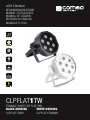
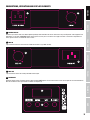
CLPFLAT1TW
TUNABLE WHITE LED FLAT PAR
BLACK HOUSING WHITE HOUSING
CLPFLAT1TWIR CLPFLAT1TWIRWH
USER´S MANUAL
BEDIENUNGSANLEITUNG
MANUEL D`UTILISATION
MANUAL DE USUARIO
INSTRUKCJA OBSŁUGI
MANUALE D‘ USO

CONTENTS / INHALTSVERZEICHNIS / CONTENU / CONTENIDO / TREŚĆ / CONTENUTO
ENGLISH
PREVENTIVE MEASURES 3-4
INTRODUCTION 4
CONNECTIONS, OPERATING AND DISPLAY ELEMENTS 5-6
OPERATION 6-7
REMOTE CONTROL (OPTIONAL) 8
DMX TECHNOLOGY 9
TECHNICAL DATA 10
MANUFACTURER’S DECLARATIONS 10-11
DMX CONTROL 57-58
DEUTSCH
SICHERHEITSHINWEISE 12-13
EINFÜHRUNG 13
ANSCHLÜSSE, BEDIEN- UND ANZEIGEELEMENTE 14-15
BEDIENUNG 15-16
FERNBEDIENUNG (OPTIONAL) 17
DMX TECHNIK 18
TECHNISCHE DATEN 19
HERSTELLERERKLÄRUNGEN 19-20
DMX STEUERUNG 57-58
FRANCAIS
MESURES PRÉVENTIVES 21-22
INTRODUCTION 22
RACCORDEMENTS,
ÉLÉMENTS DE COMMANDE ET D’AFFICHAGE 23-24
MODE D’EMPLOI 24-25
COMMANDE À DISTANCE (EN OPTION) 26
TECHNOLOGIE DMX 27
FICHE TECHNIQUE 28
DÉCLARATIONS DU FABRICANT 29
PILOTAGE EN MODE DMX 57-58
ESPAÑOL
MEDIDAS DE SEGURIDAD 30-31
INTRODUCCIÓN 31-32
CONEXIONES, MANDOS Y ELEMENTOS DE VISUALIZACIÓN 32-33
FUNCIONAMIENTO 34
MANDO A DISTANCIA (OPCIONAL) 35
TECNOLOGÍA DMX 36
DATOS TÉCNICOS 37
DECLARACIONES DEL FABRICANTE 38
CONTROL DMX 57-58
POLSKI
ŚRODKI OSTROŻNOŚCI 39-40
WPROWADZENIE 40-41
PRZYŁĄCZA, ELEMENTY OBSŁUGOWE I WSKAŹNIKOWE 41-42
OBSŁUGA 42-43
PILOT ZDALNEGO STEROWANIA (OPCJONALNY) 44
TECHNIKA DMX 45
DANE TECHNICZNE 46
OŚWIADCZENIA PRODUCENTA 47
STEROWANIE DMX 57-58
ITALIANO
MISURE PRECAUZIONALI 48-49
INTRODUZIONE 49-50
CONNESSIONI, ELEMENTI DI COMANDO E VISUALIZZAZIONE 50-51
UTILIZZO 51-52
TELECOMANDO (OPZIONALE) 53
TECNOLOGIA DMX 54
DATI TECNICI 55
DICHIARAZIONI DEL PRODUTTORE 56
CONTROLLO DMX 57-58

ITALIANOPOLSKIESPAÑOL
FRANCAISDEUTSCHENGLISH
3
DMX
ENGLISH
YOU‘VE MADE THE RIGHT CHOICE!
We have designed this product to operate reliably over many years. Please read this User‘s Manual carefully, so that you can begin making
optimum use of your Cameo Light product quickly. Learn more about Cameo Light on our website WWW.CAMEOLIGHT.COM.
PREVENTIVE MEASURES
1. Please read these instructions carefully.
2. Keep all information and instructions in a safe place.
3. Follow the instructions.
4. Observe all safety warnings. Never remove safety warnings or other information from the equipment.
5. Use the equipment only in the intended manner and for the intended purpose.
6. Use only sufficiently stable and compatible stands and/or mounts (for fixed installations). Make certain that wall mounts are properly installed and
secured. Make certain that the equipment is installed securely and cannot fall down.
7. During installation, observ e the applicable safety regulations for your country.
8. Never install and operate the equipment near radiators, heat registers, ovens or other sources of heat. Make certain that the equipment is always
installed so that is cooled sufficiently and cannot overheat.
9. Never place sources of ignition, e.g., burning candles, on the equipment.
10. Ventilation slits must not be blocked.
11. Keep a minimum distance of 20 cm around and above the device.
12. Do not use this equipment in the immediate vicinity of water (does not apply to special outdoor equipment - in this case, observe the
special instructions noted below. Do not expose this equipment to flammable materials, fluids or gases. Avoid direct sunlight!
13. Make certain that dripping or splashed water cannot enter the equipment. Do not place containers filled with liquids, such as vases or
drinking vessels, on the equipment.
14. Make certain that objects cannot fall into the device.
15. Use this equipment only with the accessories recommended and intended by the manufacturer.
16. Do not open or modify this equipment.
17. After connecting the equipment, check all cables in order to prevent damage or accidents, e.g., due to tripping hazards.
18. During transport, make certain that the equipment cannot fall down and possibly cause property damage and personal injuries.
19. If your equipment is no longer functioning properly, if fluids or objects have gotten inside the equipment or if it has been damaged in anot
her way, switch it off immediately and unplug it from the mains outlet (if it is a powered device). This equipment may only be repaired by
authorized, qualified personnel.
20. Clean the equipment using a dry cloth.
21. Comply with all applicable disposal laws in your country. During disposal of packaging, please separate plastic and paper/cardboard.
22. Plastic bags must be kept out of reach of children.
23. Please note that changes or modifications not expressly approved by the party responsible for compliance could void the user´s authority
to operate the equipment.
FOR EQUIPMENT THAT CONNECTS TO THE POWER MAINS:
24. CAUTION: If the power cord of the device is equipped with an earthing contact, then it must be connected to an outlet with a protective
ground. Never deactivate the protective ground of a power cord.
25. If the equipment has been exposed to strong fluctuations in temperature (for example, after transport), do not switch it on immediately.
Moisture and condensation could damage the equipment. Do not switch on the equipment until it has reached room temperature.
26. Before connecting the equipment to the power outlet, first verify that the mains voltage and frequency match the values specified on the
equipment. If the equipment has a voltage selection switch, connect the equipment to the power outlet only if the equipment values and the
mains power values match. If the included power cord or power adapter does not fit in your wall outlet, contact your electrician.
27. Do not step on the power cord. Make certain that the power cable does not become kinked, especially at the mains outlet and/or power
adapter and the equipment connector.
28. When connecting the equipment, make certain that the power cord or power adapter is always freely accessible. Always disconnect the
equipment from the power supply if the equipment is not in use or if you want to clean the equipment. Always unplug the power cord and
power adapter from the power outlet at the plug or adapter and not by pulling on the cord. Never touch the power cord and power adapter
with wet hands.
29. Whenever possible, avoid switching the equipment on and off in quick succession because otherwise this can shorten the useful life of
the equipment.
30. IMPORTANT INFORMATION: Replace fuses only with fuses of the same type and rating. If a fuse blows repeatedly, please contact an
authorised service centre.
31. To disconnect the equipment from the power mains completely, unplug the power cord or power adapter from the power outlet.
32. If your device is equipped with a Volex power connector, the mating Volex equipment connector must be unlocked before it can be re-
moved. However, this also means that the equipment can slide and fall down if the power cable is pulled, which can lead to personal injuries
and/or other damage. For this reason, always be careful when laying cables.
33. Unplug the power cord and power adapter from the power outlet if there is a risk of a lightning strike or before extended periods of disuse.
34. The device must only be installed in a voltage-free condition (disconnect the mains plug from the mains).
35. Dust and other debris inside the unit may cause damage. The unit should be regularly serviced or cleaned (no guarantee) depending on
ambient conditions (dust etc., nicotine, fog) by qualified personnel to prevent overheating and malfunction.
36. Please keep a distance of at least 0.5 m to any combustible materials.
37. Power cables to power multiple devices must have a cross-section of at least 1.5 mm². Within the EU, the cables must correspond to
H05VV-F, or similar. Suitable cables are offered by Adam Hall. With these cables, you can connect multiple devices via the power OUT connection

4
DEUTSCHFRANCAIS
ESPAÑOL
ENGLISH
ITALIANO POLSKI
DMX
to the power IN connection of an additional device. Make sure that the total current consumption of all connected devices does not exceed the
specified value on all connected devices (label on the device). Make sure to keep power cable connections as short as possible.
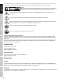
CAUTION:
To reduce the risk of electric shock, do not remove cover (or back). There are no user serviceable parts
inside. Maintenance and repairs should be exclusively carried out by qualified service personnel.
The warning triangle with lightning symbol indicates dangerous uninsulated voltage inside the unit, which may cause an
electrical shock.
The warning triangle with exclamation mark indicates important operating and maintenance instructions.
Warning! This symbol indicates a hot surface. Certain parts of the housing can become hot during operation. After use, wait for
a cool-down period of at least 10 minutes before handling or transporting the device.
Warning! This device is designed for use below 2000 metres in altitude.
Warning! This product is not intended for use in tropical climates.
CAUTION! HIGH VOLUMES IN AUDIO PRODUCTS!
This device is meant for professional use. Therefore, commercial use of this equipment is subject to the respectively applicable national
accident prevention rules and regulations. As a manufacturer, Adam Hall is obligated to notify you formally about the existence of potential
health risks.
Hearing damage due to high volume and prolonged exposure: When in use, this product is capable of producing high sound-pressure levels
(SPL) that can lead to irreversible hearing damage in performers, employees, and audience members. For this reason, avoid prolonged
exposure to volumes in excess of 90 dB.
INTRODUCTION
TUNABLE WHITE LED FLAT PAR
CLPFLAT1TWIR (black casing)
CLPFLAT1TWIRWH (white casing)
CONTROL FUNCTIONS
1-channel, 2-channel, 3-channel and 7-channel DMX control
Optional infrared remote control
Master/slave modes
Standalone operation
FEATURES
7 bright 4 W cool white/warm white LEDs. 15 colour temperature presets. Brightness and stroboscope effect can be controlled from oper-
ating panel Master/slave functions. Rugged, flat casing. Noiseless due to convection cooling. Highly durable long-life LEDs. Double bracket.
Optional infrared remote control. Operating voltage 100–240 V AC. Power consumption 22 W
OPERATION
The Cameo FLAT1 TW IR is a DMX-512-controllable spotlight which can also be operated as a standalone unit and in master/slave mode. An
integrated IR sensor enables optional IR remote control.

ITALIANOPOLSKIESPAÑOL
FRANCAISDEUTSCHENGLISH
5
DMX
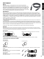
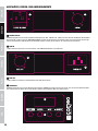
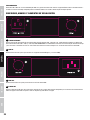
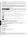
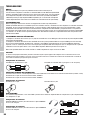
CONNECTIONS, OPERATING AND DISPLAY ELEMENTS
1
POWER IN/FUSE
IEC mains input socket with fuse holder. Operating voltage 100–240 V AC / 50–60 Hz. Connection using the IEC power cable supplied. Fuse
F3AL/250 V (5 x 20 mm). IMPORTANT: When replacing the fuse, only use a fuse of the same type and value. In the event of repeated fuse
failure, please contact an authorised service centre.
2
DMX IN
3-pin male XLR socket for connection to a DMX control device (e.g. DMX console).
3
DMX OUT
3-pin female XLR socket for sending the DMX control signal.
4
POWER OUT
IEC power output socket. Facilitates power supply to other CAMEO lights. Ensure that the total current consumption of all connected devices
does not exceed the value specified on the device in amperes (A).
21
3
4
5
6

6
DEUTSCHFRANCAIS
ESPAÑOL
ENGLISH
ITALIANO POLSKI
DMX
5
DISPLAY
The LED display shows the current operating mode and other system settings. The display disappears after 70 seconds of inactivity and is
re-activated as soon as one of the four keys MODE, ENTER, UP or DOWN is pressed.
6
OPERATING KEYS
MODE Select standalone functions, DMX mode and DMX address, slave mode and device settings.
ENTER Enter values and confirm changes.
Use the UP and DOWN keys to change brightness, stroboscope speed and DMX address.
OPERATION
NOTE
A few seconds after connecting the spotlight correctly to the mains it is ready for operation and the previously selected operating mode is activated.
INDIVIDUAL COLOUR TEMPERATURE
In order to set an individual colour temperature by mixing cold white and warm white and to create a preferred stroboscope effect, press
MODE repeatedly until “C” appears on the display and then press ENTER. Now use UP and DOWN to select “Cuxx” (cold white), “uuxx”
(warm white) or “CFxx” (stroboscope) and press ENTER to set the value, according to preference, between 00 and 99 using UP and DOWN
(CF00 = stroboscope deactivated, CF01 = slowest and CF99 = fastest stroboscope speed). Confirm your entry by pressing ENTER.
- / - / -
COLOUR TEMPERATURE PRESETS
In order to select one of the 15 colour temperature presets and set the brightness and stroboscope effect according to preference, press
MODE repeatedly until “Pr” appears on the display and then press ENTER. Now use UP and DOWN to select “Prxx” (Preset 1–15), confirm
by pressing ENTER and select a preset according to preference (preset 01 = cold white, preset 15 = warm white). Confirm by pressing
ENTER. Now use UP and DOWN once again to select “Pdxx” (dimmer) or “PFxx” (stroboscope) and press ENTER to set the value, according
to preference, between 00 and 99 using UP and DOWN (PF00 = stroboscope deactivated, PF01 = slowest and PF99 = fastest stroboscope
speed). Confirm your entry by pressing ENTER.
- / - / -
DIMMER RESPONSE
Use this menu item to set how the spotlight responds to changes in the DMX value in the dimmer channel. Press MODE repeatedly until
“drES” (Dimmer Response) is displayed and then press ENTER twice. Now set as desired using UP and DOWN. Confirm your entry by
pressing ENTER.
LEd = The spotlight responds abruptly to changes in the DMS value.
hALo = The spotlight responds like a halogen lamp, with gentle changes in brightness.
/

ITALIANOPOLSKIESPAÑOL
FRANCAISDEUTSCHENGLISH
7
DMX
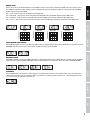
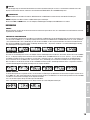
DIMMER CURVE
Use this menu item to set how the brightness of the spotlight increases or decreases in relation to the DMX value in the dimmer channel.
Press MODE repeatedly until “dCUr” (Dimmer Curve) is displayed and then press ENTER twice. Now set as desired using UP and DOWN.
Confirm your entry by pressing ENTER.
dC1 = Linear – light intensity increases linearly with the DMX value.
dC2 = Exponential – light intensity can be finely adjusted at lower DMX values and broadly adjusted at higher DMX values.
dC3 = Logarithmic – light intensity can be broadly adjusted at lower DMX values and finely adjusted at higher DMX values.
dC4 = S-curve – light intensity can be finely adjusted at lower and higher DMX values and broadly adjusted at medium DMX values.
/ / /
linear
DMX value
Light intensity
exponential
DMX value
Light intensity
logarithmic
DMX value
Light intensity
S-curve
DMX value
Light intensity
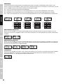
CONFIGURE DMX START ADDRESS
Press MODE repeatedly until the current DMX start address setting is displayed (Axxx) and then press ENTER. Now set as desired using UP
and DOWN (hold down key to quickly change values). Confirm your entry by pressing ENTER.
-
DMX MODE SETTING
Press MODE repeatedly until the current DMX mode setting is displayed (xCh) and then press ENTER. Now set as desired using UP and DOWN.
Confirm your entry by pressing ENTER. DMX tables with the channel assignments can be found in these instructions under DMX CONTROL.
/ / /
SLAVE MODE
Press the MODE button repeatedly until "SLAV" appears on the display. Now connect the slave and the master units (same model) with
a DMX cable and enable one of the standalone modes on the master unit (individual colour temperature “C”, colour temperature presets
“Pr”). The slave unit will now follow the master unit.

8
DEUTSCHFRANCAIS
ESPAÑOL
ENGLISH
ITALIANO POLSKI
DMX
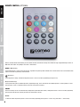
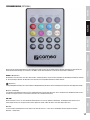
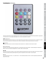
REMOTE CONTROL (OPTIONAL)
Aim the infrared remote control directly at the infrared sensor on the front of the lamp. The maximum range is approximately 8 metres. In
DMX and slave modes, the spotlight’s IR sensor is deactivated.
ON/OFF – BL (Blackout)
The blackout button is used to switch off all LEDs, regardless of operating mode enabled via the remote control. Press the blackout button
again to reactivate the previously selected mode.
(Brightness)
4-level brightness setting. The different brightness levels can be accessed by repeatedly pressing this key.
FL (Flash/Stroboscope)
4-level speed setting for the stroboscope effect (repeated pressing). Level 1 deactivates the stroboscope effect, Level 2 produces a slow
flash frequency, Level 3 a medium frequency and Level 4 the fastest frequency.
CW/WW
Use these two keys to mix an individual colour temperature (cold white/warm white). 10 brightness levels can be accessed by repeatedly
pressing the respective key, whereby the LEDs are switched off at Level 1.
Pr+/Pr-
15 different colour temperature presets can be accessed by repeatedly pressing the Pr+ and Pr- keys (cold white –> warm white).

ITALIANOPOLSKIESPAÑOL
FRANCAISDEUTSCHENGLISH
9
DMX
DMX TECHNOLOGY
DMX-512
DMX (Digital Multiplex) is the designation for a universal transmission protocol for
communications between corresponding devices and controllers. A DMX controller sends
DMX data to the connected DMX device(s). The DMX data is always transmitted as a serial
data stream that is forwarded from one connected device to the next via the "DMX IN" and
"DMX OUT" connectors (XLR plug-type connectors) that are found on every DMX-capable
device, provided the maximum number of devices does not exceed 32 units. The last device
in the chain needs to be equipped with a terminator (terminating resistor).
DMX CONNECTION
DMX is the common "language" via which a very wide range of types and models of equipment from various manufacturers can
be connected with one another and controlled via a central controller, provided that all of the devices and the controller are DMX
compatible. For optimum data transmission, it is necessary to keep the connecting cables between the individual devices as short as
possible. The order in which the devices are integrated in the DMX network has no influence on the addresses. Thus the device with
the DMX address 1 can be located at any position in the (serial) DMX chain: at the beginning, at the end or somewhere in the middle.
If the DMX address 1 is assigned to a device, the controller "knows" that it should send all data allocated to address 1 to this device
regardless of its position in the DMX network.
SERIAL CONNECTION OF MULTIPLE LIGHTS
1. Connect the male XLR connector (3-pin or 5-pin) of the DMX cable to the DMX output (female XLR socket) of the first DMX device
(e.g. DMX-Controller).
2. Connect the female 3-pin XLR connector of the DMX cable connected to the first projector to the DMX input (male 3-pin socket)
of the next DMX device. In the same way, connect the DMX output of this device to the DMX input of the next device and repeat until
all devices have been connected. Please note that as a rule, DMX devices are connected in series and connections cannot be shared
without active splitters. The maximum number of DMX devices in a DMX chain should not exceed 32 units.
The Adam Hall 3 STAR, 4 STAR, and 5 STAR product ranges include an extensive selection of suitable cables.
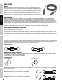
DMX CABLES
When fabricating your own cables, always observe the illustrations on this page. Never connect the shielding of the cable to the ground
contact of the plug, and always make certain that the shielding does not come into contact with the housing of the XLR plug. If the shielding
is connected to the ground, this can lead to short-circuiting and system malfunctions.
Pin Assignment
DMX cable with 3-pin XLR connectors: DMX cable with 5-pin XLR connectors (pin 4 and 5 are not used):
Shield
2
3
1
2
3
1
1
2
3
4
5
1
2
3
4
5
Shield
DMX TERMINATORS (TERMINATING RESISTORS)
To prevent system errors, the last device in a DMX chain needs to be equipped with a terminating resistor (120 ohm, 1/4 Watt).
3-pin XLR connector with a terminating resistor: K3DMXT3
5-pin XLR connector with a terminating resistor: K3DMXT5
Pin Assignment
3-pin XLR connector: 5-pin XLR connector:
2
3
1
1
2
3
4
5
DMX ADAPTER
The combination of DMX devices with 3-pin connectors and DMX devices with 5-pin connectors in a DMX chain is possible with suitable
adapters.
Pin Assignment
DMX Adapter 5-pin XLR male to 3-pin XLR female: K3DGF0020
Pins 4 and 5 are not used.
Pin Assignment
DMX Adapter 3-pin XLR male to 5-pin XLR female: K3DHM0020
Pins 4 and 5 are not used.

10
DEUTSCHFRANCAIS
ESPAÑOL
ENGLISH
ITALIANO POLSKI
DMX
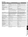
TECHNICAL DATA
Model name: CLPFLAT1TWIR CLPFLAT1TWIRWH
Product Type: LED Par Can LED Par Can
Type: Flat Can Flat Can
Colour spectrum: Warm white/cold white (3400–7000 K) Warm white/cold white (3400–7000 K)
No. of LEDs: 7 7
LED type: 4 W Dual LED 4 W Dual LED
Refresh rate: 3000 Hz 3000 Hz
Beam angle: 25° 25°
DMX input: 3-pin male XLR 3-pin male XLR
DMX output: 3-pin female XLR 3-pin female XLR
DMX mode: 1-channel, 2-channel, 3-channel, 7-channel 1-channel, 2-channel, 3-channel, 7-channel
DMX functions: Master dimmer, 15 colour temperature presets,
cold white, warm white, stroboscope, 4 dimmer
curves, dimmer response
Master dimmer, 15 colour temperature presets,
cold white, warm white, stroboscope, 4 dimmer
curves, dimmer response
Standalone functions: 15 colour temperature presets, manual mixing
(CW/WW), stroboscope, master/slave mode
15 colour temperature presets, manual mixing
(CW/WW), stroboscope, master/slave mode
Control: USITT DMX512, IR remote control (optional) DMX512, IR remote control (optional)
Operating controls: Mode, Enter, Up, Down, IR remote control
(optional)
Mode, Enter, Up, Down, IR remote control
(optional)
Indicators: 4-digit LED display 4-digit LED display
Power supply connection: IEC input and output socket IEC input and output socket
Operating voltage: 100–240 V AC / 50–60 Hz. 100–240 V AC / 50–60 Hz.
Power consumption: 22 W 22 W
Fuse: F3AL/250 V (5 x 20 mm) F3AL/250 V (5 x 20 mm)
Ambient temperature (for
operation):
0–40°C 0–40°C
Relative air humidity: <85%, non-condensing <85%, non-condensing
Light intensity (@ 1 m): 6000 lx 6000 lx
Lighting power: 1220 lm 1220 lm
Housing material: ABS/metal ABS/metal
Housing colour: black white
Cooling: convection convection
Dimensions (W x H x D, without
bracket):
180 x 175 x 115 mm 180 x 175 x 115 mm
Weight: 1.2 kg 1.2 kg
Additional features: Double bracket included, IR remote control
optional
Double bracket included, IR remote control
optional
MANUFACTURER´S DECLARATIONS
MANUFACTURER‘S WARRANTY & LIMITATIONS OF LIABILITY
You can find our current warranty conditions and limitations of liability at: http://www.adamhall.com/media/shop/downloads/documents/
manufacturersdeclarations.pdf. To request warranty service for a product, please contact Adam Hall GmbH, Daimler Straße 9,
61267 Neu Anspach / Email: [email protected] / +49 (0)6081 / 9419-0.
CORRECT DISPOSAL OF THIS PRODUCT
(valid in the European Union and other European countries with a differentiated waste collection system)
This symbol on the product, or on its documents indicates that the device may not be treated as household waste. This is to avoid
environmental damage or personal injury due to uncontrolled waste disposal. Please dispose of this product separately from other waste
and have it recycled to promote sustainable economic activity. Household users should contact either the retailer where they purchased
this product, or their local government office, for details on where and how they can recycle this item in an environmentally friendly manner.
Business users should contact their supplier and check the terms and conditions of the purchase contract. This product should not be mixed
with other commercial waste for disposal.

ITALIANOPOLSKIESPAÑOL
FRANCAISDEUTSCHENGLISH
11
DMX
CE Compliance
Adam Hall GmbH states that this product meets the following guidelines (where applicable):
R&TTE (1999/5/EC) or RED (2014/53/EU) from June 2017
Low voltage directive (2014/35/EU)
EMV directive (2014/30/EU)
RoHS (2011/65/EU)
The complete declaration of conformity can be found at www.adamhall.com.
Furthermore, you may also direct your enquiry to [email protected].

12
DEUTSCHFRANCAIS
ESPAÑOL
ENGLISH
ITALIANO POLSKI
DMX
DEUTSCH
SIE HABEN DIE RICHTIGE WAHL GETROFFEN!
Dieses Gerät wurde unter hohen Qualitätsanforderungen entwickelt und gefertigt, um viele Jahre einen reibungslosen Betrieb zu gewähr-
leisten. Bitte lesen Sie diese Bedienungsanleitung sorgfältig, damit Sie Ihr neues Produkt von Cameo Light schnell und optimal einsetzen
können. Weitere Informationen über Cameo Light erhalten Sie auf unserer Website WWW.CAMEOLIGHT.COM.
SICHERHEITSHINWEISE
1. Lesen Sie diese Anleitung bitte sorgfältig durch.
2. Bewahren Sie alle Informationen und Anleitungen an einem sicheren Ort auf.
3. Befolgen Sie die Anweisungen.
4. Beachten Sie alle Warnhinweise. Entfernen Sie keine Sicherheitshinweise oder andere Informationen vom Gerät.
5. Verwenden Sie das Gerät nur in der vorgesehenen Art und Weise.
6. Verwenden Sie ausschließlich stabile und passende Stative bzw. Befestigungen (bei Festinstallationen). Stellen Sie sicher, dass Wandhalterungen
ordnungsgemäß installiert und gesichert sind. Stellen Sie sicher, dass das Gerät sicher installiert ist und nicht herunterfallen kann.
7. Beachten Sie bei der Installation die für Ihr Land geltenden Sicherheitsvorschriften.
8. Installieren und betreiben Sie das Gerät nicht in der Nähe von Heizkörpern, Wärmespeichern, Öfen oder sonstigen Wärmequellen. Sorgen
Sie dafür, dass das Gerät immer so installiert ist, dass es ausreichend gekühlt wird und nicht überhitzen kann.
9. Platzieren Sie keine Zündquellen wie z.B. brennende Kerzen auf dem Gerät.
10. Lüftungsschlitze dürfen nicht blockiert werden.
11. Halten Sie einen Mindestabstand von 20 cm seitlich und oberhalb des Geräts ein.
12. Betreiben Sie das Gerät nicht in unmittelbarer Nähe von Wasser. Bringen Sie das Gerät nicht mit brennbaren Materialien, Flüssigkeiten
oder Gasen in Berührung. Direkte Sonneneinstrahlung vermeiden!
13. Sorgen Sie dafür, dass kein Tropf- oder Spritzwasser in das Gerät eindringen kann. Stellen Sie keine mit Flüssigkeit gefüllten Behältnisse
wie Vasen oder Trinkgefäße auf das Gerät.
14. Sorgen Sie dafür, dass keine Gegenstände in das Gerät fallen können.
15. Betreiben Sie das Gerät nur mit dem vom Hersteller empfohlenen und vorgesehenen Zubehör.
16. Öffnen Sie das Gerät nicht und verändern Sie es nicht.
17. Überprüfen Sie nach dem Anschluss des Geräts alle Kabelwege, um Schäden oder Unfälle, z. B. durch Stolperfallen zu vermeiden.
18. Achten Sie beim Transport darauf, dass das Gerät nicht herunterfallen und dabei möglicherweise Sach- und Personenschäden verursachen kann.
19. Wenn Ihr Gerät nicht mehr ordnungsgemäß funktioniert, Flüssigkeiten oder Gegenstände in das Geräteinnere gelangt sind, oder das
Gerät anderweitig beschädigt wurde, schalten Sie es sofort aus und trennen es von der Netzsteckdose (sofern es sich um ein aktives Gerät
handelt). Dieses Gerät darf nur von autorisiertem Fachpersonal repariert werden.
20. Verwenden Sie zur Reinigung des Geräts ein trockenes Tuch.
21. Beachten Sie alle in Ihrem Land geltenden Entsorgungsgesetze. Trennen Sie bei der Entsorgung der Verpackung bitte Kunststoff und
Papier bzw. Kartonagen voneinander.
22. Kunststoffbeutel müssen außer Reichweite von Kindern aufbewahrt werden.
23. Sämtliche vom Benutzer vorgenommenen Änderungen und Modifikationen, denen die für die Einhaltung der Richtlinien verantwortliche
Partei nicht ausdrücklich zugestimmt hat, können zum Entzug der Betriebserlaubnis für das Gerät führen.
BEI GERÄTEN MIT NETZANSCHLUSS:
24. ACHTUNG: Wenn das Netzkabel des Geräts mit einem Schutzkontakt ausgestattet ist, muss es an einer Steckdose mit Schutzleiter
angeschlossen werden. Deaktivieren Sie niemals den Schutzleiter eines Netzkabels.
25. Schalten Sie das Gerät nicht sofort ein, wenn es starken Temperaturschwankungen ausgesetzt war (beispielsweise nach dem Transport).
Feuchtigkeit und Kondensat könnten das Gerät beschädigen. Schalten Sie das Gerät erst ein, wenn es Zimmertemperatur erreicht hat.
26. Bevor Sie das Gerät an die Steckdose anschließen, prüfen Sie zuerst, ob die Spannung und die Frequenz des Stromnetzes mit den auf
dem Gerät angegebenen Werten übereinstimmen. Verfügt das Gerät über einen Spannungswahlschalter, schließen Sie das Gerät nur an die
Steckdose an, wenn die Gerätewerte mit den Werten des Stromnetzes übereinstimmen. Wenn das mitgelieferte Netzkabel bzw. der mitgelie-
ferte Netzadapter nicht in Ihre Netzsteckdose passt, wenden Sie sich an Ihren Elektriker.
27. Treten Sie nicht auf das Netzkabel. Sorgen Sie dafür, dass spannungsführende Kabel speziell an der Netzbuchse bzw. am Netzadapter
und der Gerätebuchse nicht geknickt werden.
28. Achten Sie bei der Verkabelung des Geräts immer darauf, dass das Netzkabel bzw. der Netzadapter stets frei zugänglich ist. Trennen Sie
das Gerät stets von der Stromzuführung, wenn das Gerät nicht benutzt wird, oder Sie das Gerät reinigen möchten. Ziehen Sie Netzkabel und
Netzadapter immer am Stecker bzw. am Adapter und nicht am Kabel aus der Steckdose. Berühren Sie Netzkabel und Netzadapter niemals
mit nassen Händen.
29. Schalten Sie das Gerät möglichst nicht schnell hintereinander ein und aus, da sonst die Lebensdauer des Geräts beeinträchtigt werden könnte.
30. WICHTIGER HINWEIS: Ersetzen Sie Sicherungen ausschließlich durch Sicherungen des gleichen Typs und Wertes. Sollte eine Sicherung
wiederholt auslösen, wenden Sie sich bitte an ein autorisiertes Servicezentrum.
31. Um das Gerät vollständig vom Stromnetz zu trennen, entfernen Sie das Netzkabel bzw. den Netzadapter aus der Steckdose.
32. Wenn Ihr Gerät mit einem Volex-Netzanschluss bestückt ist, muss der passende Volex-Gerätestecker entsperrt werden, bevor er entfernt
werden kann. Das bedeutet aber auch, dass das Gerät durch ein Ziehen am Netzkabel verrutschen und herunterfallen kann, wodurch Perso-
nen verletzt werden und/oder andere Schäden auftreten können. Verlegen Sie Ihre Kabel daher immer sorgfältig.
33. Entfernen Sie Netzkabel und Netzadapter aus der Steckdose bei Gefahr eines Blitzschlags oder wenn Sie das Gerät länger nicht verwenden.
34. Das Gerät darf nur im spannungsfreien Zustand (Trennung des Netzsteckers vom Stromnetz) installiert werden.
35. Staub und andere Ablagerungen im Inneren des Geräts können es beschädigen. Das Gerät sollte je nach Umgebungsbedingungen
(Staub, Nikotin, Nebel etc.) regelmäßig von qualifiziertem Fachpersonal gewartet bzw. gesäubert werden (keine Garantieleistung),
um Überhitzung und Fehlfunktionen zu vermeiden.

ITALIANOPOLSKIESPAÑOL
FRANCAISDEUTSCHENGLISH
13
DMX
36. Der Abstand zu brennbaren Materialien muss mindestens 0,5 m betragen.
37. Netzleitungen zur Spannungsversorgung mehrerer Geräte müssen mindestens 1,5 mm² Aderquerschnitt aufweisen. In der EU müssen
die Leitungen H05VV-F, oder gleichartig, entsprechen. Geeignete Leitungen werden von Adam Hall angeboten. Mit diesen Leitungen können
Sie mehrere Geräte über den Power out Anschluss mit dem Power IN Anschluss eines weiteren Gerätes verbinden. Beachten Sie, dass die
gesamte Stromaufnahme aller angeschlossenen Geräte den vorgegebenen Wert nicht überschreitet (Aufdruck auf dem Gerät). Achten Sie
darauf, Netzleitungen so kurz wie möglich zu halten.
ACHTUNG
Entfernen Sie niemals die Abdeckung, da sonst das Risiko eines elektrischen Schlages besteht. Im
Inneren des Geräts befinden sich keine Teile, die vom Bediener repariert oder gewartet werden können.
Lassen Sie Wartung und Reparaturen ausschließlich von qualifiziertem Servicepersonal durchführen.
Das gleichseitige Dreieck mit Blitzsymbol warnt vor nichtisolierten, gefährlichen Spannungen im Geräteinneren, die einen
elektrischen Schlag verursachen können.
Das gleichseitige Dreieck mit Ausrufungszeichen kennzeichnet wichtige Bedienungs- und Wartungshinweise.
Warnung! Dieses Symbol kennzeichnet heiße Oberflächen. Während des Betriebs können bestimmte Teile des Gehäuses heiß
werden. Berühren oder transportieren Sie das Gerät nach einem Einsatz erst nach einer Abkühlzeit von mindestens 10 Minuten.
Warnung! Dieses Gerät ist für eine Nutzung bis zu einer Höhe von maximal 2000 Metern über dem Meeresspiegel bestimmt.
Warnung! Dieses Gerät ist nicht für den Einsatz in tropischen Klimazonen bestimmt.
VORSICHT! WICHTIGE HINWEISE IN BEZUG AUF LICHT-PRODUKTE!
1. Das Produkt ist für den professionellen Einsatz im Bereich der Veranstaltungstechnik entwickelt worden und ist nicht für die Raumbeleuchtung in
Haushalten geeignet.
2. Blicken Sie niemals, auch nicht kurzzeitig, direkt in den Lichtstrahl.
3. Blicken Sie niemals mit optischen Geräten wie Vergrößerungsgläsern in den Lichtstrahl.
4. Stroboskopeffekte können unter Umständen bei empfindlichen Menschen epileptische Anfälle auslösen! Epilepsiekranke Menschen
sollten daher unbedingt Orte meiden, an denen Stroboskope eingesetzt werden.
EINFÜHRUNG
TUNABLE WHITE LED FLAT PAR
CLPFLAT1TWIR (schwarzes Gehäuse)
CLPFLAT1TWIRWH (weißes Gehäuse)
STEUERUNGSFUNKTIONEN
1-Kanal, 2-Kanal, 3-Kanal und 7-Kanal DMX-Steuerung
Steuerung über optionale Infrarot-Fernbedienung
Master/Slave-Betrieb
Standalone Funktion
EIGENSCHAFTEN
7 leuchtstarke 4W Kaltweiß / Warmweiß LEDs. 15 Farbtemperatur-Presets. Helligkeit und Stroboskopeffekt über Bedienpanel steuerbar.
Master/Slave-Funktionalität. Robustes, flaches Gehäuse. Geräuschlos durch Konvektionskühlung. Longlife-LEDs mit besonders langer
Lebensdauer. Doppelbügel. Steuerung über Infrarot-Fernbedienung (optional). Betriebsspannung 100V-240V AC. Leistungsaufnahme 22W
BEDIENUNG
Der Cameo FLAT1 TW IR ist ein DMX-512-steuerbarer Scheinwerfer und lässt sich ebenso als Standalone-Gerät und im Master/Slave-Modus
betreiben. Der integrierte IR-Sensor ermöglicht die Steuerung über eine optionale IR-Fernbedienung.

14
DEUTSCHFRANCAIS
ESPAÑOL
ENGLISH
ITALIANO POLSKI
DMX
ANSCHLÜSSE, BEDIEN- UND ANZEIGEELEMENTE
1
POWER IN/FUSE
IEC-Netzeingangsbuchse mit Sicherungshalter. Betriebsspannung 100 - 240V AC / 50 - 60Hz. Anschluss über das mitgelieferte IEC-Netzkabel.
Sicherung F3AL / 250V (5 x 20 mm). WICHTIGER HINWEIS: Ersetzen Sie die Sicherung ausschließlich durch eine Sicherung des gleichen Typs
und mit gleichen Werten. Sollte die Sicherung wiederholt auslösen, wenden Sie sich bitte an ein autorisiertes Servicezentrum.
2
DMX IN
3-polige männliche XLR-Buchse zum Anschließen eines DMX-Kontrollgerätes (z.B. DMX-Pult).
3
DMX OUT
3-polige weibliche XLR-Buchse zum Weiterleiten des DMX-Steuersignals.
4
POWER OUT
IEC Netzausgangsbuchse. Dient der Netzversorgung weiterer CAMEO Scheinwerfer. Achten Sie darauf, dass die gesamte Stromaufnahme
aller angeschlossenen Geräte den auf dem Gerät in Ampere (A) angegebenen Wert nicht überschreitet.
21
3
4
5
6

ITALIANOPOLSKIESPAÑOL
FRANCAISDEUTSCHENGLISH
15
DMX
BEDIENUNG
HINWEIS
Wenige Sekunden nachdem der Scheinwerfer korrekt am Stromnetz angeschlossen wird, ist er betriebsbereit und die Betriebsart, die zuvor
angewählt war, wird aktiviert.
INDIVIDUELLE FARBTEMPERATUR
Um eine individuelle Farbtemperatur durch Mischen von Kaltweiß und Warmweiß und den Stroboskop-Effekt nach Wunsch einzustellen, drü-
cken Sie so oft auf MODE, bis „C„ im Display angezeigt wird und drücken auf ENTER. Mit UP und DOWN wählen Sie nun „Cuxx“ (Kaltweiß),
„uuxx“ (Warmweiß) oder „CFxx“ (Stroboskop) aus und drücken auf ENTER, um den entsprechenden Wert nach Wunsch von 00 bis 99 mit
Hilfe von UP und DOWN einzustellen (CF00 = Stroboskop deaktiviert, CF01 = langsamste und CF99 = schnellste Stroboskopgeschwindig-
keit). Bestätigen Sie die Eingabe mit ENTER.
- / - / -
FARBTEMPERATUR-PRESETS
Um eines der 15 Farbtemperatur-Presets, die Helligkeit und den Stroboskop-Effekt nach Wunsch einzustellen, drücken Sie so oft auf MODE,
bis „Pr „ im Display angezeigt wird und drücken dann auf ENTER. Mit UP und DOWN wählen Sie nun „Prxx“ (Preset 1 - 15) aus, bestätigen
mit ENTER und wählen ein Preset nach Wunsch aus (Preset 01 = Kaltweiß, Preset 15 = Warmweiß). Bestätigen Sie mit ENTER. Wählen
Sie nun wiederum mit UP und DOWN „Pdxx“ (Dimmer) oder „PFxx“ (Stroboskop) aus und drücken auf ENTER, um den entsprechenden
Wert nach Wunsch von 00 bis 99 mit Hilfe von UP und DOWN einzustellen (PF00 = Stroboskop deaktiviert, PF01 = langsamste und PF99 =
schnellste Stroboskopgeschwindigkeit). Bestätigen Sie die Eingabe mit ENTER.
- / - / -
DIMMER-REAKTION
In diesem Menüpunkt kann eingestellt werden, wie der Strahler auf Änderungen des DMX-Werts im Dimmer-Kanal reagiert. Drücken Sie so
oft auf MODE, bis „drES“ (Dimmer Response) angezeigt wird und drücken 2x auf ENTER um nun die Einstellung mit Hilfe von UP und DOWN
nach Wunsch durchzuführen. Bestätigen Sie die Eingabe mit ENTER.
LEd = Der Strahler reagiert abrupt auf Änderungen des DMX-Werts.
hALo = Der Strahler verhält sich ähnlich einem Halogenstrahler mit sanften Helligkeitsänderungen.
/
5
DISPLAY
Das LED-Display zeigt den aktuellen Betriebsmodus und weitere Systemeinstellungen an. Nach ca. 70 Sekunden Inaktivität erlischt das
Display und wird wieder aktiviert, sobald einer der 4 Bedientaster MODE, ENTER, UP und DOWN betätigt wird.
6
BEDIENTASTEN
MODE Auswählen der Standalone-Funktionen, DMX-Betriebsart und DMX-Adresse, Slave-Betrieb, sowie Geräte-Einstellungen.
ENTER Ermöglicht einen Wert zu ändern und Wertänderungen zu bestätigen.
Nutzen Sie die UP und DOWN Tasten, um z.B. Helligkeit, Stroboskopgeschwindigkeit, oder DMX-Adresse zu ändern.

16
DEUTSCHFRANCAIS
ESPAÑOL
ENGLISH
ITALIANO POLSKI
DMX
DIMMERKURVE
In diesem Menüpunkt kann eingestellt werden, wie die Helligkeit des Strahlers im Verhältnis zum DMX-Wert im Dimmer-Kanal zu- oder
abnimmt. Drücken Sie so oft auf MODE, bis „dCUr“ (Dimmer Curve) angezeigt wird und drücken 2x auf ENTER um nun die Einstellung mit Hilfe
von UP und DOWN nach Wunsch durchzuführen. Bestätigen Sie die Eingabe mit ENTER.
dC1 = Linear, die Lichtintensität verläuft linear mit dem DMX-Wert.
dC2 = Exponentiell, die Lichtintensität lässt sich im unteren DMX-Wertbereich fein und im oberen DMX-Wertbereich grob einstellen.
dC3 = Logarithmisch, die Lichtintensität lässt sich im unteren DMX-Wertbereich grob und im oberen DMX-Wertbereich fein einstellen.
dC4 = S-Kurve, die Lichtintensität lässt sich im unteren und oberen DMX-Wertbereich fein und im mittleren DMX-Wertbereich grob einstellen.
/ / /
linear
DMX-Wert
Lichtintensität
exponentiell
DMX-Wert
Lichtintensität
logarithmisch
DMX-Wert
Lichtintensität
S-Kurve
DMX-Wert
Lichtintensität
DMX-STARTADRESSE EINSTELLEN
Drücken Sie so oft auf MODE, bis die aktuell eingestellte DMX-Startadresse angezeigt wird (Axxx) und drücken auf ENTER, um nun die
Einstellung mit Hilfe von UP und DOWN nach Wunsch durchzuführen (lang drücken für schnelle Wertänderung). Bestätigen Sie die Eingabe
mit ENTER.
-
DMX-BETRIEBSART EINSTELLEN
Drücken Sie so oft auf MODE, bis die aktuell eingestellte DMX-Betriebsart angezeigt wird (xCh) und drücken auf ENTER, um nun die Einstel-
lung mit Hilfe von UP und DOWN nach Wunsch durchzuführen. Bestätigen Sie die Eingabe mit ENTER. DMX-Tabellen mit den Kanalbelegun-
gen finden Sie in dieser Anleitung unter DMX STEUERUNG.
/ / /
SLAVE-BETRIEB
Drücken Sie so oft auf MODE, bis im Display „SLAV“ angezeigt wird. Verbinden Sie nun die Slave- und die Master-Einheit (gleiches Modell)
mit Hilfe eines DMX-Kabels und aktivieren in der Master-Einheit eine der Standalone Betriebsarten (Individuelle Farbtemperatur „C“,
Farbtemperatur-Presets „Pr“). Nun folgt die Slave-Einheit der Master-Einheit.

ITALIANOPOLSKIESPAÑOL
FRANCAISDEUTSCHENGLISH
17
DMX
FERNBEDIENUNG (OPTIONAL)
Richten Sie die Infrarot-Fernbedienung in Sichtverbindung direkt auf den auf der Vorderseite des Strahlers verbauten Infrarot-Sensor. Die
maximale Reichweite beträgt circa 8 Meter. In der DMX- und der Slave-Betriebsart ist der Sensor des Strahlers deaktiviert.
ON/OFF - BL (Blackout)
Die Blackout-Taste dient dazu, alle LEDs abzuschalten, unabhängig davon, welche von der Fernbedienung kontrollierten Betriebsart aktiviert
ist. Bei nochmaligem Drücken der Blackout-Taste wird die zuvor ausgewählte Betriebsart wieder aktiviert.
(Brightness)
4-stufige Helligkeitseinstellung. Die unterschiedlichen Helligkeitsabstufungen können durch mehrmaliges Drücken dieser Taste abgerufen werden.
FL (Flash / Stroboskop)
4-stufige Geschwindigkeitseinstellung für den Stroboskop-Effekt (mehrmaliges Drücken). Stufe 1 deaktiviert den Stroboskop-Effekt, Stufe 2
erzeugt eine langsame, Stufe 3 eine mittlere und Stufe 4 die schnellste Blitzfrequenz.
CW / WW
Nutzen Sie diese 2 Taster, um eine individuelle Farbtemperatur zu mischen (Kaltweiß / Warmweiß). 10 Helligkeitsstufen können durch
mehrmaliges Drücken des entsprechenden Tasters abgerufen werden, wobei bei Stufe 1 die LEDs abgeschaltet sind.
Pr+ / Pr-
15 verschiedene Farbtemperatur-Presets können mit Hilfe der Taster Pr+ und Pr- durch wiederholtes Drücken abgerufen werden
(Kaltweiß -> Warmweiß).

18
DEUTSCHFRANCAIS
ESPAÑOL
ENGLISH
ITALIANO POLSKI
DMX
DMX TECHNIK
DMX-512
DMX (Digital Multiplex) ist die Bezeichnung für ein universelles Übertragungsprotokoll für
die Kommunikation zwischen entsprechenden Geräten und Controllern. Ein DMX-Controller
sendet DMX-Daten an das/die angeschlossene(n) DMX-Gerät(e). Die DMX-Datenübertragung
erfolgt stets als serieller Datenstrom, der über die an jedem DMX-fähigen Gerät vorhandenen
DMX IN- und DMX OUT-Anschlüsse (XLR-Steckverbinder) von einem angeschlossenen
Gerät an das nächste weitergeleitet wird, wobei die maximale Anzahl der Geräte 32 nicht
überschreiten darf. Das letzte Gerät der Kette ist mit einem Abschlussstecker (Terminator) zu
bestücken.
DMX-VERBINDUNG:
DMX ist die gemeinsame "Sprache", über die sich die unterschiedlichsten Gerätetypen und Modelle verschiedener Hersteller
miteinander verkoppeln und über einen zentralen Controller steuern lassen, sofern sämtliche Geräte und der Controller DMX-
kompatibel sind. Für eine optimale Datenübertragung ist es erforderlich, die Verbindungskabel zwischen den einzelnen Geräten so
kurz wie möglich zu halten. Die Reihenfolge, in der die Geräte in das DMX-Netzwerk eingebunden sind, hat keinen Einfluss auf die
Adressierung. So kann sich das Gerät mit der DMX-Adresse 1 an einer beliebigen Position in der (seriellen) DMX-Kette befinden, am
Anfang, am Ende oder irgendwo in der Mitte. Wird einem Gerät die DMX-Adresse 1 zugewiesen, "weiß" der Controller, dass er alle
der Adresse 1 zugeordneten Daten an dieses Gerät senden soll, ungeachtet seiner Position im DMX-Verbund.
SERIELLE VERKOPPLUNG MEHRERER SCHEINWERFER
1. Verbinden Sie den männlichen XLR-Stecker (3-Pol oder 5-Pol) des DMX-Kabels mit dem DMX-Ausgang (weibliche XLR-Buchse)
des ersten DMX-Geräts (z.B. DMX-Controller).
2. Verbinden Sie den weibliche XLR-Stecker des an den ersten Scheinwerfer angeschlossenen DMX-Kabels mit dem DMX-Eingang
(männliche XLR-Buchse) des nächsten DMX-Geräts. Verbinden Sie den DMX-Ausgang dieses Geräts in der gleichen Weise mit dem
DMX-Eingang des nächsten Geräts und so weiter. Bitte beachten Sie, dass DMX-Geräte grundsätzlich seriell verschaltet werden und
die Verbindungen nicht ohne aktiven Splitter geteilt werden können. Die maximale Anzahl der DMX-Geräte einer DMX-Kette darf 32
nicht überschreiten.
Eine umfangreiche Auswahl geeigneter DMX-Kabel finden Sie in den Adam Hall Produktlinien 3 STAR, 4 STAR und 5 STAR.
DMX-KABEL:
Beachten Sie bei der Anfertigung eigener Kabel unbedingt die Abbildungen auf dieser Seite. Verbinden Sie auf keinen Fall die Abschirmung
des Kabels mit dem Massekontakt des Steckers, und achten Sie darauf, dass die Abschirmung nicht mit dem XLR-Steckergehäuse in
Kontakt kommt. Hat die Abschirmung Massekontakt, kann dies zu Systemfehlern führen.
Steckerbelegung:
DMX-Kabel mit 3-Pol XLR-Steckern: DMX-Kabel mit 5-Pol XLR-Steckern (Pin 4 und 5 sind nicht belegt.):
Shield
2
3
1
2
3
1
1
2
3
4
5
1
2
3
4
5
Shield
DMX-ABSCHLUSSSTECKER (TERMINATOR):
Um Systemfehler zu vermeiden, ist das letzte Gerät einer DMX-Kette mit einem Abschlusswiderstand zu bestücken (120 Ohm, 1/4 Watt).
3-Pol XLR-Stecker mit Abschlusswiderstand: K3DMXT3
5-Pol XLR-Stecker mit Abschlusswiderstand: K3DMXT5
Steckerbelegung:
3-Pol XLR-Stecker: 5-Pol XLR-Stecker:
2
3
1
1
2
3
4
5
DMX-ADAPTER:
Die Kombination von DMX-Geräten mit 3-Pol Anschlüssen und DMX-Geräten mit 5-Pol Anschlüssen in einer DMX-Kette ist mit Hilfe von
Adaptern ebenso möglich.
Steckerbelegung
DMX-Adapter 5-Pol XLR male auf 3-Pol XLR female: K3DGF0020
Pin 4 und 5 sind nicht belegt.
Steckerbelegung
DMX-Adapter 3-Pol XLR male auf 5-Pol XLR female: K3DHM0020
Pin 4 und 5 sind nicht belegt.

ITALIANOPOLSKIESPAÑOL
FRANCAISDEUTSCHENGLISH
19
DMX
TECHNISCHE DATEN
Modellbezeichnung: CLPFLAT1TWIR CLPFLAT1TWIRWH
Produktart: LED Par Can LED Par Can
Typ: Flat Can Flat Can
Farbspektrum: Warmweiß/Kaltweiß (3400K - 7000K) Warmweiß/Kaltweiß (3400K - 7000K)
LED Anzahl: 7 7
LED Typ: 4W Dual LED 4W Dual LED
Wiederholrate: 3000 Hz 3000 Hz
Abstrahlwinkel: 25° 25°
DMX-Eingang: 3-Pol XLR männlich 3-Pol XLR männlich
DMX-Ausgang: 3-Pol XLR weiblich 3-Pol XLR weiblich
DMX-Modus: 1-Kanal, 2-Kanal, 3-Kanal, 7-Kanal 1-Kanal, 2-Kanal, 3-Kanal, 7-Kanal
DMX Funktionen: Master Dimmer, 15 Farbtemperatur-Presets,
Kaltweiß, Warmweiß, Stroboskop, 4 Dimmerkur-
ven, Dimmer Reaktion
Master Dimmer, 15 Farbtemperatur-Presets,
Kaltweiß, Warmweiß, Stroboskop, 4 Dimmerkur-
ven, Dimmer Reaktion
Standalone Funktionen: 15 Farbtemperatur-Presets, manuelles Mischen
(CW/WW), Stroboskop, Master/Slave-Betrieb
15 Farbtemperatur-Presets, manuelles Mischen
(CW/WW), Stroboskop, Master/Slave-Betrieb
Steuerung: USITT DMX512, IR-Fernbedienung (optional) DMX512, IR-Fernbedienung (optional)
Bedienelemente: Mode, Enter, Up, Down, IR-Fernbedienung
(optional)
Mode, Enter, Up, Down, IR-Fernbedienung
(optional)
Anzeigeelemente: 4-stelliges LED-Display 4-stelliges LED-Display
Stromversorgungsanschluss: IEC-Buchse Ein- und Ausgang IEC-Buchse Ein- und Ausgang
Betriebsspannung: 100 - 240 V AC / 50 - 60 Hz 100 - 240 V AC / 50 - 60 Hz
Leistungsaufnahme: 22 W 22 W
Sicherung: F3AL / 250V (5 x 20mm) F3AL / 250V (5 x 20mm)
Umgebungstemperatur (in Betrieb): 0°C - 40°C 0°C - 40°C
Relative Luftfeuchtigkeit: <85%, nicht kondensierend <85%, nicht kondensierend
Beleuchtungsstärke (@ 1m): 6000 lx 6000 lx
Lichtstrom: 1220 lm 1220 lm
Gehäusematerial: ABS, Metall ABS, Metall
Gehäusefarbe: schwarz weiß
Kühlung: Konvektion Konvektion
Abmessungen (B x H x T, ohne
Bügel):
180 x 175 x 115 mm 180 x 175 x 115 mm
Gewicht: 1,2 kg 1,2 kg
Weitere Eigenschaften: Doppelbügel inklusive, IR-Fernbedienung
optional
Doppelbügel inklusive, IR-Fernbedienung
optional
HERSTELLERERKLÄRUNGEN
HERSTELLERGARANTIE & HAFTUNGSBESCHRÄNKUNG
Unsere aktuellen Garantiebedingungen und Haftungsbeschränkung finden Sie unter: http://www.adamhall.com/media/shop/downloads/
documents/manufacturersdeclarations.pdf. Im Service Fall wenden Sie sich bitte an Adam Hall GmbH, Daimlerstraße 9, 61267 Neu Anspach
/ E-Mail [email protected] / +49 (0)6081 / 9419-0.
KORREKTE ENTSORGUNG DIESES PRODUKTS
(Gültig in der Europäischen Union und anderen europäischen Ländern mit Mülltrennung) Dieses Symbol auf dem Produkt oder
dazugehörigen Dokumenten weist darauf hin, dass das Gerät am Ende der Produktlebenszeit nicht zusammen mit dem normalen
Hausmüll entsorgt werden darf, um Umwelt- oder Personenschäden durch unkontrollierte Abfallentsorgung zu vermeiden. Bitte entsorgen
Sie dieses Produkt getrennt von anderen Abfällen und führen es zur Förderung nachhaltiger Wirtschaftskreisläufe dem Recycling zu. Als Pri-
vatkunde erhalten Sie Informationen zu umweltfreundlichen Entsorgungsmöglichkeiten über den Händler, bei dem das Produkt erwor¬ben
wurde, oder über die entsprechenden regionalen Behörden. Als gewerblicher Nutzer kontaktieren Sie bitte Ihren Lieferanten und prüfen
die ggf. vertraglich vereinbarten Konditionen zur Entsorgung der Geräte. Dieses Produkt darf nicht zusammen mit anderen gewerblichen
Abfällen entsorgt werden.

20
DEUTSCHFRANCAIS
ESPAÑOL
ENGLISH
ITALIANO POLSKI
DMX
CE-Konformität
Hiermit erklärt die Adam Hall GmbH, dass dieses Produkt folgenden Richtlinien entspricht (soweit zutreffend):
R&TTE (1999/5/EG) bzw. RED (2014/53/EU) ab Juni 2017
Niederspannungsrichtlinie (2014/35/EU)
EMV-Richtlinie (2014/30/EU)
RoHS (2011/65/EU)
Die vollständige Konformitätserklärung finden Sie unter www.adamhall.com.
Des Weiteren können Sie diese auch unter [email protected] anfragen.
La page est en cours de chargement...
La page est en cours de chargement...
La page est en cours de chargement...
La page est en cours de chargement...
La page est en cours de chargement...
La page est en cours de chargement...
La page est en cours de chargement...
La page est en cours de chargement...
La page est en cours de chargement...
La page est en cours de chargement...
La page est en cours de chargement...
La page est en cours de chargement...
La page est en cours de chargement...
La page est en cours de chargement...
La page est en cours de chargement...
La page est en cours de chargement...
La page est en cours de chargement...
La page est en cours de chargement...
La page est en cours de chargement...
La page est en cours de chargement...
La page est en cours de chargement...
La page est en cours de chargement...
La page est en cours de chargement...
La page est en cours de chargement...
La page est en cours de chargement...
La page est en cours de chargement...
La page est en cours de chargement...
La page est en cours de chargement...
La page est en cours de chargement...
La page est en cours de chargement...
La page est en cours de chargement...
La page est en cours de chargement...
La page est en cours de chargement...
La page est en cours de chargement...
La page est en cours de chargement...
La page est en cours de chargement...
La page est en cours de chargement...
La page est en cours de chargement...
La page est en cours de chargement...
La page est en cours de chargement...
-
 1
1
-
 2
2
-
 3
3
-
 4
4
-
 5
5
-
 6
6
-
 7
7
-
 8
8
-
 9
9
-
 10
10
-
 11
11
-
 12
12
-
 13
13
-
 14
14
-
 15
15
-
 16
16
-
 17
17
-
 18
18
-
 19
19
-
 20
20
-
 21
21
-
 22
22
-
 23
23
-
 24
24
-
 25
25
-
 26
26
-
 27
27
-
 28
28
-
 29
29
-
 30
30
-
 31
31
-
 32
32
-
 33
33
-
 34
34
-
 35
35
-
 36
36
-
 37
37
-
 38
38
-
 39
39
-
 40
40
-
 41
41
-
 42
42
-
 43
43
-
 44
44
-
 45
45
-
 46
46
-
 47
47
-
 48
48
-
 49
49
-
 50
50
-
 51
51
-
 52
52
-
 53
53
-
 54
54
-
 55
55
-
 56
56
-
 57
57
-
 58
58
-
 59
59
-
 60
60


Cameo CLPFLAT1TWIRWH Le manuel du propriétaire
- Taper
- Le manuel du propriétaire
- Ce manuel convient également à
dans d''autres langues
Documents connexes
-
Cameo Matrix Panel 3 WW Manuel utilisateur
-
-
Cameo Auro Spot 200 Manuel utilisateur
-
Cameo CLTRIBAR200IRWH Manuel utilisateur
-
Cameo CLSTORM Manuel utilisateur
-
-
-
-
-