Ingersoll Rand SS4L5 Single-Stage Twin Cylinder Pro Air Compressor, 5 HP, 230V, 135 PSI, 60 Gallons Le manuel du propriétaire
- Catégorie
- Compresseurs d'air
- Taper
- Le manuel du propriétaire

Save These Instructions
Owner’s Manual
Manual del usuario
ES
Manuel de l’utilisateur
FR
Owner’s Manual
EN
Single Stage Reciprocating Air Compressor
Model SS4L5
80448251
Revision E
January 2020
RELEASED 31/Jan/2020 19:25:50 GMT

PRODUCT REGISTRATION
To register your product with an Extended Warranty Kit, go to www.IRrecip.com/
registration in your Web browser. Otherwise, you must contact your local full service
air solutions provider.
To locate your nearest provider:
1. Go to www.ingersollrandproducts.com in your Web browser.
2. Select Americas Region from main page.
3. Click “Customer Service”.
4. Click “Contact Us”.
5. Click “Compressed Air Solutions”.
6. If you are located in the United States, enter your 5-digit zip code in the field to
find your local full service air solutions provider and then press “Search on Zip
Code”. If you are located outside of the United States, select your country from
the “International Locations” list and then press “Submit”.
GENERAL INFORMATION
nIntroduction
This manual provides safe and reliable instructions for the installation, operation
and maintenance of your Ingersoll Rand air compressor. Carefully read this
manual before attempting to operate or perform any maintenance. If you are
uncertain about any of the instructions or procedures provided in this manual,
contact Ingersoll Rand. We recommend you retain this manual, and all
publications provided with your air compressor, in a location which is accessible
to all personnel who operate and service your compressed air equipment.
nApplication
Your air compressor unit is suitable for operating air tools, caulking guns, grease
guns, sandblasters, etc. Depending on your application, the following accessories
may be required:
lAn air pressure regulator to adjust the air pressure entering the tool or
accessory.
lAn air line filter for removal of moisture and oil vapor in compressed air.
lAn in-line lubricator to prolong the life of air tools.
lSeparate air transformers which combine the functions of air regulation
and/or moisture and dirt removal.
Contact your nearest authorized dealer or call 1-800-AIR-SERV for more
information on air tools and accessories for your application.
nAdditional References
Unless otherwise stated, dimensions, weights and measurements are provided in
standard U. S. measure followed in parentheses by the metric conversion. Any
torque values given are stated in inch or foot pounds followed by the
Newton-meter equivalent in parentheses.Electrical characteristics are given in
voltage-phase-hertz.
EXPLANATION OF SAFETY SIGNAL WORDS
Indicates an imminently hazardous situation
which, if not avoided, will result in death or
serious injury.
Indicates a potentially hazardous situation
which, if not avoided, could result in death or
serious injury.
Indicates a potentially hazardous situation
which, if not avoided, may result in minor or
moderate injury or property damage.
Indicates information or a company policy that
relates directly or indirectly to the safety of
personnel or protection of property.
RECEIPT & INSPECTION
Ensure adequate lifting equipment is available for unloading and moving the
compressor to the installation site.
lLifting equipment must be properly rated for the weight of the
compressor. Weight information is printed on a label attached to the
shipping container.
lLift the compressor by the shipping skid only.
lDo not use the motor lifting eye to lift the entire compressor. The motor
lifting eye is for removing the motor from the compressor only.
lDo not work on or walk under the compressor while it is suspended.
Use suitable lifting equipment (i.e. forklift) to lift and transport the compressor to
the installation site. Ensure the lifting equipment, straps, etc. are capable of
supporting the weight of the compressor.
Before signing the delivery receipt, inspect for damage and missing parts. If
damage or missing parts are apparent, make the appropriate notation on the
delivery receipt, then sign the receipt. Immediately contact the carrier for an
inspection.
All material must be held in the receiving location for the carrier’s inspection.
Delivery receipts that have been signed without a notation of damage or missing
parts are considered to be delivered “clear.”Subsequent claims are then
considered to be concealed damage claims. Settle damage claims directly with
the transportation company.
If you discover damage after receiving the compressor (concealed damage), the
carrier must be notified within 15 days of receipt and an inspection must be
requested by telephone with confirmation in writing. On concealed damage
claims, the burden of establishing that the compressor was damaged in transit
reverts back to the claimant.
Read the compressor nameplate to verify it is the model ordered, and read the
motor nameplate to verify it is compatible with your electrical conditions.
Make sure electrical enclosures and components are appropriate for the
installation environment.
280448251 Rev. E
EN
WARNING
CAUTION
NOTICE
WARNING
DANGER
RELEASED 31/Jan/2020 19:25:50 GMT

GENERAL SAFETY RULES
80448251 Rev. E 3
EN
INTAKE AIR. CAN CONTAIN CARBON MONOXIDE OR OTHER
CONTAMINANTS. WILL CAUSE SERIOUS INJURY OR DEATH.
INGERSOLL-RAND AIR COMPRESSORS ARE NOT DESIGNED, INTENDED
OR APPROVED FOR BREATHING AIR. COMPRESSED AIR SHOULD NOT BE
USED FOR BREATHING AIR APPLICATIONS UNLESS TREATED IN
ACCORDANCE WITH ALL APPLICABLE CODES AND REGULATIONS.
DANGER / PELIGRO / DANGER
AIRE DE ADMISIÓN. PUEDE CONTENER MONÓXIDO DE CARBONO
U OTROS CONTAMINANTES. PUEDE CAUSAR LESIONES GRAVES
O LA MUERTE. LOS COMPRESORES DE AIRE INGERSOLL-RAND NO
ESTÁN DISEÑADOS, DESTINADOS PARA AIRE RESPIRABLE. NO SE DEBE
USAR EL AIRE COMPRIMIDO PARA APLICACIONES DE AIRE RESPIRABLE
A MENOS QUE SE TRATE DE ACUERDO CON TODAS LAS NORMAS Y
REGLAMENTOS CORRESPONDIENTES.
AIR D’ADMISSION. PEUT CONTENIR DU MONOXYDE DE CARBONE
OU D’AUTRES CONTAMINANTS. CAUSE DES BLESSURES GRAVES
OU LA MORT. LES COMPRESSEURS INGERSOLL-RAND N’ONT PAS ÉTÉ
CONÇUS, NI DESTINÉS, NI APPROUVÉS POUR LA COMPRESSION D’AIR
RESPIRABLE. L’AIR COMPRIMÉ NE DOIT PAS ÊTRE UTILISÉ POUR LA
RESPIRATION À MOINS QU’IL N’AIT ÉTÉ TRAITÉ D’APRÈS LES NORMES ET
RÈGLEMENTS EN VIGUEUR POUR CETTE APPLICATION. 54653662-00
HOT SURFACES. CAN CAUSE SERIOUS INJURY.
DO NOT TOUCH. ALLOW TO COOL BEFORE SERVICING.
SUPERFICIE CALIENTE. PUEDE CAUSAR LESIONES GRAVES.
NO TOCAR. DEJE QUE SE ENFRIE ANTES DE DAR SERVICIO.
SURFACE CHAUDE. PEUT CAUSER DES BLESSURES GRAVES.
NE PAS TOUCHER. ATTENDRE LE REFROIDISSEMENT AVANT DE
RÉPARER.
56276652-01
WARNING/ADVERTENCIA/AVERTISSEMENT
High Pressure Air. Rusted tanks can cause explosion and severe injury or
death. Receiver under pressure. Operator should relieve tank pressure before
performing maintenance. Operate manual drain daily or after each use. Manual
drain valve located on bottom of tank.
Aire a alta presión. Los tanques oxidados pueden causar una explosión y
lesiones graves o la muerte. Receptor bajo presión. El operador deberá
aliviar la presión del tanque antes de dar servicio de mantenimiento. Debe
drenarse manualmente cada día o después de cada uso. La válvula de
drenaje manual está ubicada en la parte inferior del tanque.
Air à haute pression. Les réservoirs rouillés peuvent provoquer une explosion
et causer des blessures graves ou la mort. Récepteur sous pression.
L'opérateur doit détendre la pression du réservoir avant d'effectuer l'entre-
tien. Actionner le drain manuel quotidiennement ou après chaque utilisation. Le
robinet de drain manuel est situé en bas due réservoir.
DANGER DE CHOC ÉLECTRIQUE. DÉBRANCHER LE COMPRESSEUR DU CIRCUIT
ÉLECTRIQUE D’ALIMENTATION AVANT DE FAIRE DES ENTRETIENS. NE PAS EXPOSER LE
COMPRESSEUR A LA PLUIE ET VEILLER A L’UTILISER A L’ABRI DU MOUILLE. STOCKER À
L’INTÉRIEUR.
RIESGO DE DESCARGA ELÉCTRICA. DESCONECTE EL COMPRESOR DEL CIRCUITO DE
SUMINISTRO ELÉCTRICO ANTES DE DARLE SERVICIO. NO HAGA FUNCIONAR EL COMPRE-
SOR A LA LLUVIA NI LO OPERE EN UN LUGAR HÚMEDO. ALMACÉNELO EN EL INTERIOR.
LISEZ LE MANUEL DE L’UTILISATEUR AVANT DE METTRE LE COMPRESSEUR EN
MARCHE.
LEA EL MANUAL DEL USUARIO ANTES DE HACER ARRANCAR EL COMPRESOR.
PARTES MOVILES. PUEDE CAUSAR LESIONES GRAVES. NO OPERE LA MAQUINA SI SE
HA RETIRADO EL PROTECTOR. LA MAQUINA PUEDE EMPEZAR A FUNCIONAR AUTOMATI-
CAMENTE. DESCONECTE LA ENERGIA ANTE DE DARLE SERVISIO A LA MAQUINA.
BLOQUEAR/ETIQUETAR LA MAQUINA.
PIECES TOURNANTES. PEUT CAUSER DES BLESSURES GRAVES. NE PAS OPERER
SANS PROTECTIONS. LA MACHINE PEUT COMMENCER AUTOMATIQUEMENT. DEBRACHER
AVANT LE SERVICE. VERROUILLER/ETIQUETER LA MACHINE.
RIESGO DE INCENDIO O EXPLOSIÓN. EL ARCO ELÉCTRICO PRODUCIDO POR LOS
COMPONENTES DEL COMPRESOR PUEDE ENCENDER LOS LÍQUIDOS Y VAPORES
INFLAMABLES, CAUSANDO LESIONES GRAVES. NO HAGA FUNCIONAR NUNCA EL
COMPRESOR CERCA DE LÍQUIDOS O VAPORES INFLAMABLES. SI SE UTILIZA PARA
ASPERSIÓN DE MATERIALES INFLAMABLES, DEBE MANTENERSE EL COMPRESOR A UNA
DISTANCIA MÍNIMA DE 20 PIES (6 METROS) DEL ÁREA DE ASPERSIÓN.
RISQUE D'INCENDIE OU D'EXPLOSION. LES ARCS ÉLECTRIQUES PRODUITS PAR LES
COMPOSANTS DU COMPRESSEUR PEUVENT ENFLAMMER LES LIQUIDES ET VAPEURS
INFLAMMABLES, CE QUI PEUT CAUSER DES BLESSURES GRAVES. NE JAMAIS FAIRE
MARCHER LE COMPRESSEUR À PROXIMITÉ DES LIQUIDES OU VAPEURS INFLAMMABLES.
S'IL EST UTILISÉ POUR VAPORISER DES MATIÈRES INFLAMMABLES, GARDER LE
COMPRESSEUR À 6 MÈTRES (20 PIEDS) AU MOINS DE LA ZONE DE VAPORISATION.
AIR SOUS PRESSION ELEVEE. LE CONTOURNEMENT, LA MODIFICATION OU LE
RETRAIT DE SOUPAPES DE SECURITE / DETENTE PEUT CAUSER DES BLESSURES
GRAVES OU LA MORT. NE PAS CONTOURNER, MODIFIER OF RETIRER LES SOUPAPES DE
SECURITE/DETENTE. RISQUE D'ÉCLATEMENT. UTILISER UNIQUEMENT DES PIÈCES DE
MANIPULATION D'AIR DONT LA PRESSION NOMINALE N'EST PAS INFÉRIEURE À LA
PRESSION MAXIMALE ADMISSIBLE DE TRAVAIL DE L'APPAREIL. NE JAMAIS MODIFIER OU
RÉPARER LE RÉSERVOIR; OBTENIR UN RECHANGE AUPRÈS DU CENTRE DE SERVICE.
READ OWNERS MANUAL BEFORE STARTING COMPRESSOR.
AIRE DE ALTA PRESIÓN. LA DERIVACIÓN MODIFICACIÓN O RETIRO DE LAS VÁLVULAS
DE SEGURIDAD/ALIVIO PUEDE CAUSAR LESIONES GRAVES O LA MUERTE. NO DERIVE,
MODIFIQUE O RETIRE LAS VÁLVULAS DE SEGURIDAD/ALIVIO. RIESGO DE EXPLOSIÓN.
UTILICE SOLAMENT PIEZAS DE MANIPULACIÓN DE AIRE ADECUADAS QUE SEAN
ACEPTABLES PARA PRESIONES NO MENORES A LA PRESIÓN MÁXIMA DE TRABAJO
ADMISIBLE DE LA MÁQUINA. NO MODIFIQUE NI REPARE NUNCA EL TANQUE; OBTENGA UN
REEMPLAZO DEL CENTRO DE SERVICIO.
HIGH PRESSURE AIR. BYPASSING, MODIFYING OR REMOVING SAFETY/RELIEF VALVES
CAN CAUSE SERIOUS INJURY OR DEATH. DO NOT BYPASS, MODIFY OR REMOVE
SAFETY / RELIEF VALVES. DO NOT DIRECT AIR STREAM AT BODY. RISK OF BURSTING.
USE ONLY SUITABLE AIR HANDLING PARTS ACCEPTABLE FOR PRESSURE OF NOT LESS
THAN THE MAXIMUM ALLOWABLE WORKING PRESSURE OF THE MACHINE. NEVER
MODIFY OR REPAIR TANK, OBTAIN REPLACEMENT FROM SERVICE CENTER.
MOVING PARTS. CAN CAUSE SERIOUS INJURY. DO NOT OPERATE WITH GUARDS
REMOVED. MACHINE MAY START AUTOMATICALLY. DISCONNECT POWER BEFORE
SERVICING. LOCKOUT / TAGOUT MACHINE.
RISK OF FIRE OR EXPLOSION. ELECTRICAL ARCING FROM COMPRESSOR COMPONENTS
CAN IGNITE FLAMMABLE LIQUIDS AND VAPORS WHICH CAN RESULT IN SERIOUS INJURY.
NEVER OPERATE THE COMPRESSOR NEAR FLAMMABLE LIQUIDS OR VAPORS. IF USED TO
SPRAY FLAMMABLE MATERIALS, KEEP COMPRESSOR AT LEAST 20FT AWAY FROM THE
SPRAY AREA.
RISK OF ELECTRIC SHOCK. DISCONNECT COMPRESSOR FROM ELECTRICAL SUPPLY
CIRCUIT BEFORE SERVICING. DO NOT EXPOSE COMPRESSOR TO RAIN OR OPERATE IN A
WET AREA. STORE INDOORS.
WARNING / ADVERTENCIA / AVERTISSEMENT
AVERTISSEMENT
ADVERTENCIA
WARNING
23482383-A
RELEASED 31/Jan/2020 19:25:50 GMT

480448251 Rev. E
EN
General Arrangement
INSTALLATION
RELEASED 31/Jan/2020 19:25:50 GMT

Selecting A Location
General
Select a clean, dry, well-lighted indoor area with plenty of space for proper
cooling air flow and accessibility. Locate the unit at least 12 inches (30 cm) from
walls, and make sure the main power supply is clearly identified and accessible.
Temperature
Ideal operating temperatures are between 32°F and 100°F (0°C and 37.8°C). If
temperatures consistently drop below 32°F (0°C), locate the unit inside a heated
building. If this is not possible, you must protect safety/relief valves and drain
valves from freezing.
Never operate in temperatures below 20°F (-6.6°C) or above 120°F
(48.9°C).
Humid Areas
In frequently humid areas, moisture may form in the bare pump and produce
sludge in the lubricant, causing running parts to wear out prematurely. Excessive
moisture is especially likely to occur if the unit is located in an unheated area that
is subject to large temperature changes. Two signs of excessive humidity are
external condensation on the bare pump when it cools down and a “milky”
appearance in petroleum compressor lubricant. You may be able to prevent
moisture from forming in the bare pump by increasing ventilation, operating for
longer intervals or installing a crankcase heater kit.
Noise Considerations
Consult local officials for information regarding acceptable noise levels in your
area. To reduce excessive noise, use vibration isolator pads or intake silencers,
relocate the unit or construct total enclosures or baffle walls.
Permanent Mounting
Remove the compressor from the skid before mounting. Refer to the
RECEIPT & INSPECTION section of this manual for information on lifting
and handling the compressor.
Local codes may mandate specific mounting requirements including,
but not limited to, the use of vibration isolation mounts or pads.
Mounting kits including vibration isolation mounts or pads may be
ordered through your Ingersoll Rand dealer if not included with the
compressor. Consult your local Ingersoll Rand dealer for more
information.
Secure the compressor to a solid, flat and level mounting surface.
If vibration isolation mounts or pads are included with your
compressor, they must be properly installed. Failure to install the
compressor using the vibration isolation mounts or pads provided with
the compressor and in accordance with the installation instructions
may result in mechanical failure to the compressor and cancellation of
warranty coverage.
Do not install the compressor on I-beams, open-grid flooring systems,
or non-solid surfaces.
Ingersoll Rand shall bear no responsibility for equipment installed on
non-approved vibration isolation mounts or pads or non-solid surfaces.
To mount the compressor to a concrete surface, use the following procedure:
1. Mark the location of the mounting holes.
2. Drill 2-1/4 h deep holes using a ½” concrete drill bit.
It may be helpful to use a piece of tape on the drill bit to mark the
proper depth.
3. Drill a hole through the center of each isolation pad (if supplied or mandated by
local codes).
4. Drive the anchors into the mounting holes with the threaded portion up.
5. Place the isolation pads over the anchors as shown in the illustration below.
6. Position the compressor over the drilled holes and slowly lower the compressor
feet over the holes.
7. Install the foundation bolts.
8. Install the nuts and torque each in a criss-cross pattern to 10 ft. lb.
After all mounting nuts are installed, check for receiver stress by loosening each
nut individually to check for upward movement of the foot. Upward movement
indicates the requirement for an appropriately sized metal shim to fi ll in the
open elevation under the foot. After all required shims have been inserted,
re-tighten the nuts to 10 ft. lb.
Installing The Air Inlet Filter
Do not operate the unit without the air inlet filter(s).
If the air around the unit is relatively free of dirt, install the air inlet filter at the
inlet connection at the bare pump. If remote air inlet piping or heavy duty
filtration is required, contact your dealer for information.
80448251 Rev. E 5
EN
NOTICE
NOTICE
CAUTION
CAUTION
THIS UNIT MUST BE INSTALLED ON A
LEVEL FLOOR AND TANK FEET MUST
BE SHIMMED PER THE OWNERS MANUAL.
DO NOT OPERATE THE
UNIT ON THE SHIPPING
SKID.
54521224-01
NOTICE
Typical Permanent Mounting
A = Mounting surface
B = Foundation bolt / anchor
C = Isolation pad (if supplied or required by local codes)
D = Compressor mounting foot
E = Washer
F = Nut
CAUTION
Air Inlet Filter
RELEASED 31/Jan/2020 19:25:50 GMT

nInstalling Discharge Piping
If it is necessary to install air discharge and condensate discharge piping, adhere
to the following general guidelines. Contact your dealer for more information.
lDo not use plastic pipe, rubber hose, or lead-tin soldered joints
anywhere in the compressed air system.
lIf an aftercooler, check valve, block valve, or any other restriction is
added to the compressor discharge, install a properly-sized ASME
approved safety/relief valve between the compressor discharge and the
restriction.
lIf you will be using Ingersoll Rand synthetic compressor lubricant, all
downstream piping material and system components must be
compatible. Refer to the following material compatibility list. If there
are incompatible materials present in your system, or if there are
materials not included in the list, contact your dealer or call
1-800-AIR-SERV.
Suitable:
Viton®, Teflon®, Epoxy (Glass Filled), Oil Resistant Alkyd, Fluorosilicone,
Fluorocarbon, Polysulfide, 2-Component Urethane, Nylon, Delrin®, Celcon®,
High Nitrile Rubber (Buna N. NBR more than 36% Acrylonitrile), Polyurethane,
Polyethylene, Epichlorohydrin, Polyacrylate, Melamine, Polypropylene, Baked
Phenolics, Epoxy, Modified Alkyds
(® indicates trademark of DuPont Corporation)
Not Recommended:
Neoprene, Natural Rubber, SBR Rubber, Acrylic Paint, Lacquer, Varnish,
Polystyrene, PVC, ABS, Polycarbonate, Cellulose Acetate, Low Nitrile Rubber
(Buna N. NBR less than 36% Acrylonitrile), EPDM, Ethylene Vinyl Acetate,
Latex, EPR, Acrylics, Phenoxy, Polysulfones, Styrene Acrylonitrile (San), Butyl
nGeneral Requirements
The piping, fittings, receiver tank, etc. must be certified safe for at least the
maximum working pressure of the unit. Use hard-welded or threaded steel or
copper pipes and cast iron fittings that are certified safe for the unit’s discharge
pressure and temperature. DO NOT USE PVC PLASTIC. Use pipe thread sealant on
all threads, and make up joints tightly to prevent air leaks.
nCondensate Discharge Piping
If installing a condensate discharge line, the piping must be at least one size
larger than the connection, as short and direct as possible, secured tightly and
routed to a suitable drain point. Condensate must be disposed of in accordance
with local, state, and federal laws and regulations.
lAll compressed air systems generate condensate which accumulates in
any drain point (e.g. tanks, filters, drip legs, aftercoolers, dryers). This
condensate contains lubricating oil and/or substances which may be
regulated and must be disposed of in accordance with local, state, and
federal laws and regulations.
nElectrical Wiring
lElectrical installation and service should be performed by a qualified
electrician who is familiar with all applicable local, state and federal
laws and regulations.
lThis product should be connected to a grounded, metallic, permanent
wiring system, or an equipment-grounding terminal or lead on the
product.
nGeneral
The motor rating, as shown on the motor nameplate, and the power supply must
have compatible voltage, phase and hertz characteristics.
nWire Size
The electrical wiring between the power supply and electric motor varies
according to motor horsepower. Power leads must be adequately sized to protect
against excessive voltage drop during start-up. Information for selecting the
proper wire size and securing connections should be provided with the motor. If
not, refer to the National Electric Code (NEC) or applicable local, state and federal
laws and regulations. If other electrical equipment is connected to the same
circuit, the total electrical load must be considered in selecting the proper wire
size. DO NOT USE UNDERSIZE WIRE.
nFuses
Refer to the National Electric Code to determine the proper fuse or circuit breaker
rating required. When selecting fuses, remember the momentary starting current
of an electric motor is greater than its full load current. Time-delay or “slow-blow”
fuses are recommended.
nCompressor Lubrication
lDo not operate without lubricant or with inadequate lubricant.
Ingersoll Rand is not responsible for compressor failure caused by
inadequate lubrication.
nSynthetic Lubricant
We recommend Ingersoll Rand synthetic compressor lubricant from start-up.
See the WARRANTY section for extended warranty information.
680448251 Rev. E
EN
NOTICE
Pressure switch
NOTICE
NOTICE
WARNING
AJOUTEZ D’ABORD DE L’HUILE!
• Cette pompe de compresseur est livrée sans
huile.
• Ne mettez pas en marche sans lubrifiant ou
avec un lubrifiant non approprié.
• N’utilisez pas d’huile de moteur dans la pompe
de compresseur.
• Ingersoll-Rand décline toute responsabilité pour
les pannes d’équipement causées par une
lubrification insuffisante ou incorrecte.
• Reportez-vous au mode d’emploi du
compresseur pour les recommandations
concernant le lubrifiant du compresseur.
• Installez correctement
• Vérifiez que l’alimentation électrique est
adéquate
• Contactez un électricien certifié
• Consultez le manuel d’instructions
AVIS
NOTICE
ADD OIL FIRST!
• This compressor pump is shipped without oil.
• Do not operate without lubricant or with
inadequate lubricant.
• Do not use engine oil in the compressor pump.
• Ingersoll-Rand is not responsible for
equipment failure caused by inadequate or
incorrect lubrication.
• Refer to the compressor owner's manual for
compressor lubricant recommendations.
• Install properly
• Check for adequate electrical supply
• Contact certified electrician
• Consult instruction manual
PRIMERO, LLENAR DE ACEITE!
• Se entrega esta bomba de compresor sin aceite.
• No hacer funcionar sin aceite ni con aceite
inadecuado.
• No poner aceite de motor en la bomba del
compresor.
• Ingersoll-Rand no será responsable por fallas
en el equipo debidas a lubricación
inadecuada o incorrecta.
• Consultar el manual del compresor en cuanto a
la lubricación recomendada.
• Instalar correctamente
• Verificar que la alimentación eléctrica
sea adecuada
• Consultar un electricista certificado
• Referirse al manual de instrucciones
AVISO
56289655-01
WARNING
CAUTION
Wiring schematic
RELEASED 31/Jan/2020 19:25:50 GMT

Alternate Lubricants
You may use a petroleum-based lubricant that is premium quality, does not
contain detergents, contains only anti-rust, anti-oxidation, and anti-foam agents
as additives, has a ashpoint of 440°F (227°C) or higher, and has an auto-ignition
point of 650°F (343°C) or higher.
See the petroleum lubricant viscosity table below. The table is intended as a
general guide only. Heavy duty operating conditions require heavier viscosities.
Refer specic operating conditions to your dealer for recommendations.
Temperature Around Unit Viscosity @ 100°F (37.8°C) Viscosity Grade
°F °C SUS Centistokes ISO SAE
40 & below 4.4 & below 150 32 32 10
40 - 80 4.4 - 26.7 500 110 100 30
80 - 125 26.7 - 51.0 750 165 150 40
If you use a petroleum-based compressor lubricant at start-up and decide to
convert to Ingersoll Rand synthetic compressor lubricant later on, the
compressor valves must be thoroughly decarbonized and the crankcase must be
ushed before conversion.
Filling Procedures
1. Unscrew and remove the oil ll plug (A).
2. Slowly ll the crankcase with lubricant until the lubricant reaches the top thread
of the oil ll opening and the top of the sight glass (B). Crankcase capacity is
one-half (0.5) liter.
3. Replace the oil ll plug HAND TIGHT ONLY.
OPERATION
General
Your air compressor was designed for 100% continuous duty operation with the
use of Ingersoll Rand synthetic compressor lubricant and 60% continuous duty
operation with the use of petroleum lubricant. In other words, synthetic lubricant
allows the compressor to pump continuously without cycling. Petroleum
lubricant limits the compressor to a maximum of 36 minutes of pumping time
per hour. The compressor should not cycle more than 10 times per hour.
Initial Start-Up
Follow this procedure before putting the unit into service for the rst time:
1. Set the pressure switch lever (A) to “OFF”.
2. Open the service valve fully to prevent air pressure from building in the tank.
(A=Open, B=Closed).
3. Move the pressure switch lever to “ON/AUTO”. The unit will start.
4. Run the unit for 30 minutes. Ensure the service valve is fully open and there is no
tank pressure build up.
Unusual noise or vibration indicates a problem. Do not continue to
operate until you identify and correct the source of the problem. IF
EMERGENCY CONDITIONS ARE ENCOUNTERED, SHUT OFF THE MAIN
POWER IMMEDIATELY.
5. After 30 minutes, close the service valve fully. The air receiver will ll to cut-out
pressure and the motor will stop. The unit is now ready for use.
Normal Start-Up
1. Set the pressure switch lever to “OFF”.
2. Close the service valve.
3. Attach hose and accessory.
4. Move the pressure switch lever to “ON/AUTO”. The unit will start.
5. Allow tank pressure to build. The motor will stop when tank pressure reaches
cut-out pressure.
6. Open the service valve. The unit is now ready for use.
When the receiver tank pressure drops below the factory pre-set
minimum, the pressure switch resets and restarts the unit.
When You Are Finished
1. Set the pressure switch lever to “OFF”.
2. Close the service valve fully.
3. Remove the air tool or accessory.
4. Slowly open the service valve to bleed air pressure down to 20 psig.
5. Slowly open the manual drain valve at the bottom of the tank to drain all
condensate (water).
6. Close the drain valve and the service valve for the next use.
80448251 Rev. E 7
EN
Filling Procedures
Pressure Switch Lever
Service Valve
WARNING
NOTICE
Pressure Switch :
The Pressure Switch is Pre-set at the required pressure. The range and dierential
settings ARE NOT adjustable. The Pressure Switch should not be tampered with in
any way and no attempt should be made to adjust the pressure settings as this
could damage the Switch to the point of failure and/or void any warranty for the
Pressure Switch.
RELEASED 31/Jan/2020 19:25:50 GMT

MAINTENANCE
lDisconnect, lock and tag the main power supply and release air
pressure from the system before performing maintenance.
lAll compressed air systems contain maintenance parts (e.g. lubricating
oil, filters, separators) which are periodically replaced. These used
parts may be, or may contain, substances that are regulated and must
be disposed of in accordance with local, state, and federal laws and
regulations.
lTake note of the positions and locations of parts during disassembly to
make reassembly easier. The assembly sequences and parts illustrated
may differ for your particular unit.
lAny service operations not included in this section should be
performed by an authorized service representative.
ROUTINE MAINTENANCE SCHEDULE
Daily or Before
Each Operation
lCheck lubricant level. Fill as needed.
lDrain receiver tank condensate. Open the manual
drain valve and collect and dispose of condensate
accordingly.
lCheck for unusual noise and vibration.
lEnsure beltguards and covers are securely in place.
lEnsure area around compressor is free from rags,
tools, debris, and flammable or explosive materials.
Weekly lInspect air filter element. Clean or replace if
necessary.
Monthly lInspect for air leaks. Squirt soapy water around joints
during compressor operation and watch for bubbles.
lCheck tightness of screws and bolts. Tighten as
needed.
lClean exterior.
3/500 * lChange petroleum lubricant while crankcase is warm.
12/2000 * lChange synthetic lubricant while crankcase is warm.
lReplace filter element.
* indicates months/operating hours, whichever occurs first.
nFilter Element Replacement
1. Unscrew and remove the wing nut (A) securing the filter housing (B) to its base
(C).
2. Remove the filter housing and withdraw the old filter element (D). Clean the
element with a jet of air or vacuum.
3. Install a new filter element and replace the housing, securing it in place with the
wing nut previously removed.
nOil Change
1. Remove the oil drain plug (C) and allow the lubricant to drain into a suitable
container.
2. Replace the oil drain plug.
3. Follow the filling procedures in OPERATION section.
nBelt Adjustment
nChecking Belt Tension
Check belt tension occasionally, especially if looseness is suspected. A quick
check to determine if adjustment is proper may be made by observing the slack
side of the belt for a slight bow when the unit is in operation. If a slight bow is
evident, the belt is usually adjusted satisfactorily.
nTensioning Belts
Belt tensioning can be achieved by loosening the motor anchor screws, pushing
the motor away from the pump, and retightening the motor anchor screws. The
motor can be easily moved by placing a prying tool beneath it. A commercially
available spreader or other belt tensioning device can also be helpful should
tensioning be necessary.
Follow the procedures outlined below to correctly set and measure belt tension.
1. Lay a straight edge across the top outer surface of the belt drive from pulley to
sheave.
2. At the center of the span, perpendicular to the belt, apply pressure to the outer
surface of the belt with a tension gauge. Force the belt to the deflection
indicated in the following table and compare the reading.
Deflection in Inches Min. Tension (Lb.) Max. Tension (Lb.)
0.17 3.0 6.0
Ensure the pulley and sheave are properly aligned and the motor anchor screws
are adequately retightened prior to restarting the compressor.
lImproper pulley/sheave alignment and belt tension can result in motor
overload, excessive vibration, and premature belt and/or bearing
failure. To prevent these problems from occurring, ensure the pulley
and sheave are aligned and belt tension is satisfactory after installing
new belts or tensioning existing belts.
880448251 Rev. E
EN
WARNING
NOTICE
Filter Element Replacement
Oil Change
Belt Tensioning
NOTICE
RELEASED 31/Jan/2020 19:25:50 GMT

nTank Inspection
The life of an air receiver tank is dependent upon several factors including, but
not limited to, operating conditions, ambient environments, and the level of
maintenance. The exact effect of these factors on tank life is difficult to predict;
therefore, Ingersoll Rand recommends that you schedule a certified tank
inspection within the first five years of compressor service. To arrange a tank
inspection, contact the nearest Ingersoll Rand service provider.
If the tank has not been inspected within the first 10 years of compressor service,
the tank must be taken out of service until it has passed inspection. Tanks that
fail to meet requirements must be replaced.
lFailure to replace a rusted air receiver tank could result in air receiver
tank rupture or explosion, which could cause substantial property
damage, severe personal injury, or death. Never modify or repair tank.
Obtain replacement from service center.
80448251 Rev. E 9
EN
WARNING
RELEASED 31/Jan/2020 19:25:50 GMT

TROUBLESHOOTING
ESUAC ELBISSOPMELBORP POSSIBLE SOLUTION
Abnormal piston, ring or cylinder
wear
1. Lubricant viscosity too low.
2. Lubricant level too low.
3. Detergent type lubricant being used.
4. Cylinder(s) or piston(s) scratched, worn or scored.
5. Extremely dusty atmosphere.
6. Worn cylinder nish.
1. Drain existing lubricant and rell with proper lubricant.
2. Add lubricant to crankcase to proper level.
3. Drain existing lubricant and rell with proper lubricant.
4. Repair or replace as required.
5. Install remote air inlet piping and route to source of cleaner air.
Install more eective ltration.
6. Deglaze cylinder with 180 grit ex-hone.
Air delivery drops o 1. Clogged or dirty inlet and/or discharge line lter.
2. Air leaks in air discharge piping.
3. Lubricant viscosity too high.
4. Compressor valves leaky, broken, carbonized or loose.
5. Piston rings damaged or worn (broken, rough or scratched).
Excessive end gap or side clearance.
6. Piston rings not seated, are stuck in grooves or end gaps not
staggered.
7. Cylinder(s) or piston(s) scratched, worn or scored.
8. Defective safety/relief valve.
1. Clean or replace.
2. Check tubing and connections.
3. Drain existing lubricant and rell with proper lubricant.
4. Inspect valves. Clean or replace as required. Install valve kit.
5. Install ring kit.
6. Adjust piston rings.
7. Repair or replace as required.
8. Replace.
Unit does not come up to speed 1. Loose beltwheel or motor pulley, excessive end play in motor
shaft or loose drive belts.
2. Lubricant viscosity too high.
3. Improper line voltage.
4. Compressor valves leaky, broken, carbonized or loose.
5. Defective ball bearings on crankshaft or motor shaft.
1. Check beltwheel, motor pulley, crankshaft, drive belt tension
and alignment. Repair or replace as required.
2. Drain existing lubricant and rell with proper lubricant.
3. Check line voltage and upgrade lines as required. Contact
electrician.
4. Inspect valves. Clean or replace as required.
Install valve kit.
5. Inspect bearings and replace crankshaft assembly if required.
Unit is slow to come up to speed 1. Lubricant viscosity too high.
2. Leaking check valve or check valve seat blown out.
3. Ambient temperature too low.
4. Bad motor.
1. Drain existing lubricant and rell with proper lubricant.
2. Replace check valve.
3. Relocate unit to warmer environment.
Install crankcase heater kit.
4. Replace.
Unit runs excessively hot 1. Inadequate ventilation around beltwheel.
2. Drive belts too tight or misaligned.
3. Compressor valves leaky, broken, carbonized or loose.
4. Wrong beltwheel direction of rotation.
1. Relocate unit for better air ow.
2. Adjust belts to proper tension and alignment.
3. Inspect valves. Clean or replace as required. Install valve kit.
4. Check motor wiring for proper connections. Reverse two leads
on three-phase motors.
Excessive noise during operation 1. Loose beltwheel or motor pulley, excessive end play in motor
shaft or loose drive belts.
2. Lubricant viscosity too high.
3. Lubricant level too low.
4. Compressor valves leaky, broken, carbonized or loose.
5. Carbon build-up on top of piston(s).
6. Defective ball bearings on crankshaft or motor shaft.
7. Leaking check valve or check valve seat blown out.
1. Check beltwheel, motor pulley, crankshaft, drive belt tension
and alignment. Repair or replace as required.
2. Drain existing lubricant and rell with proper lubricant.
3. Add lubricant to crankcase to proper level.
4. Inspect valves. Clean or replace as required.
Install valve kit.
5. Clean piston(s). Repair or replace as required.
6. Inspect bearings and replace crankshaft assembly if required.
7. Replace check valve.
Excessive starting and stopping 1. Air leaks in air discharge piping.
2. Leaking check valve or check valve seat blown out.
3. Excessive condensate in receiver tank.
1. Check tubing and connections.
2. Replace check valve.
3. Drain receiver tank with manual drain valve.
10 80448251 Rev. E
EN
RELEASED 31/Jan/2020 19:25:50 GMT

PROBLEM POSSIBLE CAUSE POSSIBLE SOLUTION
High oil consumption 1. Clogged or dirty inlet and/or discharge line filter.
2. Lubricant viscosity too low.
3. Detergent type lubricant being used.
4. Piston rings damaged or worn (broken, rough or scratched).
Excessive end gap or side clearance.
5. Piston rings not seated, are stuck in grooves or end gaps not
staggered.
6. Cylinder(s) or piston(s) scratched, worn or scored.
7. Connecting rod, piston pin or crankpin bearings worn or scored.
8. Crankshaft seal worn or crankshaft scored.
9. Worn cylinder finish.
1. Clean or replace.
2. Drain existing lubricant and refill with proper lubricant.
3. Drain existing lubricant and refill with proper lubricant.
4. Install ring kit.
5. Adjust piston rings.
6. Repair or replace as required.
7. Inspect all. Repair or replace as required.
8. Replace seal or crankshaft assembly.
9. Deglaze cylinder with 180 grit flex-hone.
Knocking or rattling 1. Loose beltwheel or motor pulley, excessive end play in motor
shaft or loose drive belts.
2. Compressor valves leaky, broken, carbonized or loose.
3. Carbon build-up on top of piston(s).
4. Cylinder(s) or piston(s) scratched, worn or scored.
5. Connecting rod, piston pin or crankpin bearings worn or scored.
6. Defective ball bearings on crankshaft or motor shaft.
1. Check beltwheel, motor pulley, crankshaft, drive belt tension
and alignment. Repair or replace as required.
2. Inspect valves. Clean or replace as required.
Install valve kit.
3. Clean piston(s). Repair or replace as required.
4. Repair or replace as required.
5. Inspect all. Repair or replace as required.
6. Inspect bearings and replace crankshaft assembly if required.
Lights flicker or dim when
running 1. Improper line voltage.
2. Wiring or electric service panel too small.
3. Poor contact on motor terminals or starter connections.
4. Improper starter overload heaters.
5. Poor power regulation (unbalanced line).
1. Check line voltage and upgrade lines as required. Contact
electrician.
2. Install properly sized wire or service box. Contact electrician.
3. Ensure good contact on motor terminals or starter connections.
4. Install proper starter overload heaters. Contact electrician.
5. Contact power company.
Moisture in crankcase or “milky”
appearance in petroleum
lubricant or rusting in cylinders
1. Detergent type lubricant being used.
2. Extremely light duty cycles.
3. Unit located in damp or humid location.
1. Drain existing lubricant and refill with proper lubricant.
2. Run unit for longer duty cycles.
3. Relocate unit.
Motor overload trips or draws
excessive current 1. Lubricant viscosity too high.
2. Improper line voltage.
3. Wiring or electric service panel too small.
4. Poor contact on motor terminals or starter connections.
5. Improper starter overload heaters.
6. Poor power regulation (unbalanced line).
7. Drive belts too tight or misaligned.
8. Compressor valves leaky, broken, carbonized or loose.
9. Cylinder(s) or piston(s) scratched, worn or scored.
10. Connecting rod, piston pin or crankpin bearings worn or scored.
11. Defective ball bearings on crankshaft or motor shaft.
12. Leaking check valve or check valve seat blown out.
13. Ambient temperature too low.
14. Bad motor.
1. Drain existing lubricant and refill with proper lubricant.
2. Check line voltage and upgrade lines as required. Contact
electrician.
3. Install properly sized wire or service box. Contact electrician.
4. Ensure good contact on motor terminals or starter connections.
5. Install proper starter overload heaters. Contact electrician.
6. Contact power company.
7. Adjust belts to proper tension and alignment.
8. Inspect valves. Clean or replace as required.
Install valve kit.
9. Repair or replace as required.
10. Inspect all. Repair or replace as required.
11. Inspect bearings and replace crankshaft assembly if required.
12. Replace check valve.
13. Relocate unit to warmer environment.
Install crankcase heater kit.
Convert to synthetic lubricant.
14. Replace
Motor will not start 1. Improper line voltage.
2. Wiring or electric service panel too small.
3. Poor contact on motor terminals or starter connections.
4. Improper starter overload heaters.
5. Bad motor.
1. Check line voltage and upgrade lines as required. Contact
electrician.
2. Install properly sized wire or service box. Contact electrician.
3. Ensure good contact on motor terminals or starter connections.
4. Install proper starter overload heaters. Contact electrician.
5. Replace
80448251 Rev. E 11
EN
RELEASED 31/Jan/2020 19:25:50 GMT

PROBLEM POSSIBLE CAUSE POSSIBLE SOLUTION
Oil in discharge air (oil pumping) 1. Lubricant viscosity too low.
2. Detergent type lubricant being used.
3. Piston rings damaged or worn (broken, rough or scratched).
Excessive end gap or side clearance.
4. Piston rings not seated, are stuck in grooves or end gaps not
staggered.
5. Cylinder(s) or piston(s) scratched, worn or scored.
6. Worn cylinder finish.
7. Excessive condensate in receiver tank.
1. Drain existing lubricant and refill with proper lubricant.
2. Drain existing lubricant and refill with proper lubricant.
3. Install ring kit.
4. Adjust piston rings.
5. Repair or replace as required.
6. Deglaze cylinder with 180 grit flex-hone.
7. Drain receiver tank with manual drain valve.
Oil leaking from shaft seal 1. Crankshaft seal worn or crankshaft scored. 1. Replace seal or crankshaft assembly.
Safety/relief valve “pops” 1. Clogged or dirty inlet and/or discharge line filter.
2. Compressor valves leaky, broken, carbonized or loose.
3. Defective safety/relief valve.
1. Clean or replace.
2. Inspect valves. Clean or replace as required.
Install valve kit.
3. Replace
12 80448251 Rev. E
EN
RELEASED 31/Jan/2020 19:25:50 GMT

80448251 Rev. E 13
WARRANTY AND LIMITATION OF LIABILITY
WARRANTY
Ingersoll Rand company warrants that the equipment manufactured by it and delivered hereunder shall be free of defects in material and workmanship for a
period of twelve (12) months from the date of placing the equipment in operation or eighteen (18) months from the date of shipment, whichever shall occur
rst. The foregoing warranty period shall apply to all equipment, except the following:
1. Compressors purchased with an accompanying Extended Warranty Kit that are operated solely on the included Ingersoll Rand synthetic lubricant will
have their bare compressor warranted for the earlier of twenty-four (24) months from the date of initial operation or thirty (30) months from the date of
shipment.
2. Replacement parts will be warranted for six (6) months from the date of shipment. Should any failure to conrm this warranty be reported in writing
to the company within said period, the company shall, at its option, correct such non-conrmity by suitable repair to such equipment, or furnish a
replacement part F.O.B point of shipment, provided the purchaser has installed, maintained and operated such equipment in accordance with good
industry practiced and has complied with specic recommendations of the company. Accessories or equipment furnished by the company, but
manufactured by others, shall carry whatever warranty the manufacturer conveyed to Ingersoll Rand Company and which can be passed on to the
purchaser. The company shall not be liable for any repairs, replacements, or adjustments to the equipment or any costs of labour performed by the
purchaser without company’s prior written approval.
The company makes no performance warranty unless specically stated within its proposal and the eects of corrosion, erosion and normal wear and tear are
specically excluded from the company’s warranty. In the event performance warranties are expressly included, the company’s obligation shall be to correct in
the manner and for the period of time provided above.
THE COMPANY MAKES NO OTHER WARRANTY OF REPRESENTATION OF ANY KIND WHATSOEVER, EXPRESSED OR IMPLIED, EXPECT THAT OF TITLE,
AND ALL IMPLIED WARRANTIES OF MERCHANTABILITY AND FITNESS FOR A PARTICULAR PURPOSE, AND HEREBY DISCLAIMED.
Correction by the company of non-conformities, whether patent or latent, in the manner and for the period of time provided above, shall constitute fulllment
of all liabilities of the company and its distributers for such non-conformities with respect to or arising out of such equipment.
LIMITATION OF LIABILITY
THE REMEDIES OF THE PURCHASER SET FORTH HEREIN ARE EXCLUSIVE, AND THE TOTAL LIABILITY OF THE COMPANY, ITS DISTRIBUTERS AND SUPPLIERS WITH
RESPECT TO CONTRACT OR THE EQUIPMENT AND SERVICES FURNISHED, IN CONNECTION WITH THE PERFORMANCE OR BRANCH THEREOF, OR FROM THE
MANUFACTURE, SALE, DELIVERY, INSTALLATION, REPAIR OR TECHNICAL DIRECTION COVERED BY OR FURNISHED UNDER CONTRACT, WHETHER BASED ON
CONTRACT, WARRANTY, NEGLIGIANCE, INDEMNITY, STRICT LIABILITY OR OTHERWISE SHALL NOT EXCEED THE PURCHASE PRICE OF THE UNIT OF EQUIPMENT
UPON WHICH SUCH LIABILITY IS BASED.
THE COMPANY, ITS DISTRIBUTERS AND ITS SUPPLIERS SHALL IN NO EVENT BE LIABLE TO THE PURCHASER, ANY SUCCESSORS IN INTEREST OR ANY BENEFICIARY
OR ASSIGNEE OF THE CONTRACT FOR ANY CONSEQUENTIAL, INCIDENTAL, INDIRECT, SPECIAL OR PUNITIVE DAMAGES ARISING OUT OF THIS CONTRACT
OR ANY BREACH THEREOF, OR ANY DEFECT IN, OR FAILURE OF , OR MALFUNCTION OF THE EQUIPMENT, WHETHER OR NOT BASED UPON LOSS OF USE,
LOSS PROFITS OR REVENUE, INTEREST, LOST GOODWILL, WORK STOPPAGE, IMPAIRMENT OF THE OTHER GOODS, LOSS BY REASON OF SHUTDOWN OR
NON-OPERATION, INCREASED FOR SERVICE INTERRUPTION WHETHER OR NOT SUCH LOSS OR DAMAGE IS BASED ON CONTRACT, WARRANTY, NEGLIGENCE,
INDEMNITY, STRICT LIABILITY OR OTHERWISE.
EN
RELEASED 31/Jan/2020 19:25:50 GMT

EXPLICACIÓN DE LAS PALABRAS DE
SEÑALES DE SEGURIDAD
Indica una situación peligrosa inminentemente
la cual, si no se evita, resultará en la muerte o en
lesiones graves.
Indica una situacion potencialmente peligrosa la
cual, si no se evita, resultara en la muerte o en
lesiones graves.
Indica una situacion potencialmente peligrosa la
cual, si no se evita, puede generar una lesion
menor o moderada o danos a la propiedad.
Indica informacion o una politica de la compania
que se relaciona directa o indirectamente con la
seguridad del personal o la proteccion de la
propiedad.
GARANTÍA Y REGISTRO DEL PRODUCTO
Ingersoll Rand garantiza el equipo por un periodo de doce (12) meses a partir
de la fecha en que se ponga el equipo en operacion o dieciocho (18) meses a
partir de la fecha de envio, lo que ocurra primero.
Los compresores que operan unicamente con lubricante sintetico para
compresor All Season Select tendran la bomba para compresor (la bomba unica)
garantizada por veinticuatro (24) meses a partir de la fecha de operacion inicial o
treinta (30) meses a partir de la fecha de envio, lo que suceda primero.
Para registrar su producto, debe contactar a su proveedor local de soluciones de
aire de servicio completo. Para localizar a su proveedor mas cercano:
1. Vaya a ingersollrandproducts.com en su explorador Web.
2. Seleccione la region de America en la pagina principal.
3. Haga clic en “Servicio al Cliente”.
4. Haga clic en ”Contacto”.
5. Haga clic en ”Soluciones de aire comprimido”.
6. Si usted se encuentra en Estados Unidos, ingrese su codigo postal de 5 digitos en
el campo para encontrar a su proveedor local de soluciones de aire de servicio
completo y despues presione ”Buscar por codigo postal”. Si se encuentra fuera
de Estados Unidos, seleccione su pais en la lista de “Ubicaciones Internacionales”
y despues pulse “Enviar”.
INFORMACIONES GENERALES
nIntroducción
Este manual ofrece instrucciones seguras y confi ables para la instalacion,
operacion y mantenimiento de su compresor de aire Ingersoll Rand. Lea
atentamente este manual antes de tratar de operarlo o hacer cualquier
mantenimiento. Si no esta seguro acerca de alguna de las instrucciones o
procedimientos que aparecen en este manual, comuniquese con Ingersoll Rand.
Le recomendamos que guarde este manual y todas las publicaciones que vienen
con su compresor de aire en un lugar accesible a todo el personal que opera y da
servicio a su equipo compresor de aire.
nAplicación
Su compresor de aire está adecuado para la operación de herramientas
neumáticas, pistolas de calefatear, pistolas engrasadoras, chorreadoras de arena,
etc. Se necesitan los siguientes accesorios según la aplicación:
lUn regulador de la presión de aire para ajustar la presión de aire entrante la
herramienta o accesorio.
lUn filtro de la línea de aire para eliminar la humedad y el vapor de aceite del
aire comprimido.
lUn lubricador en línea para prolongar la vida de las herramientas
neumáticas.
lTransformadores de aire separados combinando las funciones de regulación
de aire y/o la eliminación de la humedad y suciedad.
Comuníquese con su representante autorizado o llame al 1-800-AIR-SERV para
informaciones adicionales de las herramientas neumáticas y los accesorios de
aplicaciones individuas
nOtras referencias
A menos que se indique otra cosa, las dimensiones, pesos y medidas se dan en
medidas estandares de los EE.UU., seguidas entre parentesis por la conversion al
sistema metrico. Los valores de torsion dados se indican en pulgadas o pies
libras, seguidos por el equivalente en Newton-metros entre parentesis. Las
caracteristicas electricas se dan en voltaje-fase-hertzios.
RECIBO E INSPECCIÓN
Asegúrese de que existan equipos de carga adecuados para descargar y trasladar
su compresor al sitio de instalación.
lLa elevacion del equipo se debe medir adecuadamente para el peso del
compresor. La informacion de peso esta impresa en la etiqueta que esta
pegada en el contenedor de embarque.
lLevante el compresor unicamente por los patines de embarque.
lNo use el ojo de izaje del motor para levantar todo el compresor. El ojo
de izaje del motor es unicamente para quitar el motor del compresor.
lNo trabaje ni camine por debajo del compresor mientras este
suspendido.
Utilice el equipo de izaje adecuado (tal como un montacargas) para levantar y
transportar el compresor al sitio de la instalación. Asegúrese de que el equipo de
izaje, las cintas, etc. puedan soportar el peso del compresor.
Antes de firmar el recibo de entrega, asegúrese de que haya piezas que falten o
que estén dañadas. Si hay evidencia de daños o de que faltan piezas, haga la
anotación respectiva en el recibo de entrega y luego fírmelo. Comuníquese
inmediatamente con el transportista para que realice una inspección.
Todo el material se debe mantener en el lugar de recepción para la inspección
del transportista.
Los recibos de entrega firmados que no tienen anotación de daños o piezas
faltantes se consideran como prueba de una entrega “sin problemas” Cualquier
reclamo posterior se considerará como demanda por daños ocultos. Liquide
cualquier demanda por daños con la empresa de transporte.
Si descubre algún daño después de recibir el compresor (daño oculto), debe
notificar al transportista dentro de un plazo de 15 días después del recibo y
solicitar por teléfono una inspección una confirmación por escrito. En las
demandas por daños ocultos, la responsabilidad de establecer que el compresor
se dañó durante el transporte recae en la persona que hace el reclamo.
Lea la placa de identificación del compresor para verificar que corresponde al
modelo solicitado y lea la placa del motor para verificar que es compatible con
sus condiciones eléctricas.
Asegúrese de que las cajas y componentes eléctricos sean los adecuados.
14 80448251 Rev. E
ES
RELEASED 31/Jan/2020 19:25:50 GMT

80448251 Rev. E 15
ES
INTAKE AIR. CAN CONTAIN CARBON MONOXIDE OR OTHER
CONTAMINANTS. WILL CAUSE SERIOUS INJURY OR DEATH.
INGERSOLL-RAND AIR COMPRESSORS ARE NOT DESIGNED, INTENDED
OR APPROVED FOR BREATHING AIR. COMPRESSED AIR SHOULD NOT BE
USED FOR BREATHING AIR APPLICATIONS UNLESS TREATED IN
ACCORDANCE WITH ALL APPLICABLE CODES AND REGULATIONS.
DANGER / PELIGRO / DANGER
AIRE DE ADMISIÓN. PUEDE CONTENER MONÓXIDO DE CARBONO
U OTROS CONTAMINANTES. PUEDE CAUSAR LESIONES GRAVES
O LA MUERTE. LOS COMPRESORES DE AIRE INGERSOLL-RAND NO
ESTÁN DISEÑADOS, DESTINADOS PARA AIRE RESPIRABLE. NO SE DEBE
USAR EL AIRE COMPRIMIDO PARA APLICACIONES DE AIRE RESPIRABLE
A MENOS QUE SE TRATE DE ACUERDO CON TODAS LAS NORMAS Y
REGLAMENTOS CORRESPONDIENTES.
AIR D’ADMISSION. PEUT CONTENIR DU MONOXYDE DE CARBONE
OU D’AUTRES CONTAMINANTS. CAUSE DES BLESSURES GRAVES
OU LA MORT. LES COMPRESSEURS INGERSOLL-RAND N’ONT PAS ÉTÉ
CONÇUS, NI DESTINÉS, NI APPROUVÉS POUR LA COMPRESSION D’AIR
RESPIRABLE. L’AIR COMPRIMÉ NE DOIT PAS ÊTRE UTILISÉ POUR LA
RESPIRATION À MOINS QU’IL N’AIT ÉTÉ TRAITÉ D’APRÈS LES NORMES ET
RÈGLEMENTS EN VIGUEUR POUR CETTE APPLICATION. 54653662-00
HOT SURFACES. CAN CAUSE SERIOUS INJURY.
DO NOT TOUCH. ALLOW TO COOL BEFORE SERVICING.
SUPERFICIE CALIENTE. PUEDE CAUSAR LESIONES GRAVES.
NO TOCAR. DEJE QUE SE ENFRIE ANTES DE DAR SERVICIO.
SURFACE CHAUDE. PEUT CAUSER DES BLESSURES GRAVES.
NE PAS TOUCHER. ATTENDRE LE REFROIDISSEMENT AVANT DE
RÉPARER.
56276652-01
WARNING/ADVERTENCIA/AVERTISSEMENT
High Pressure Air. Rusted tanks can cause explosion and severe injury or
death. Receiver under pressure. Operator should relieve tank pressure before
performing maintenance. Operate manual drain daily or after each use. Manual
drain valve located on bottom of tank.
Aire a alta presión. Los tanques oxidados pueden causar una explosión y
lesiones graves o la muerte. Receptor bajo presión. El operador deberá
aliviar la presión del tanque antes de dar servicio de mantenimiento. Debe
drenarse manualmente cada día o después de cada uso. La válvula de
drenaje manual está ubicada en la parte inferior del tanque.
Air à haute pression. Les réservoirs rouillés peuvent provoquer une explosion
et causer des blessures graves ou la mort. Récepteur sous pression.
L'opérateur doit détendre la pression du réservoir avant d'effectuer l'entre-
tien. Actionner le drain manuel quotidiennement ou après chaque utilisation. Le
robinet de drain manuel est situé en bas due réservoir.
DANGER DE CHOC ÉLECTRIQUE. DÉBRANCHER LE COMPRESSEUR DU CIRCUIT
ÉLECTRIQUE D’ALIMENTATION AVANT DE FAIRE DES ENTRETIENS. NE PAS EXPOSER LE
COMPRESSEUR A LA PLUIE ET VEILLER A L’UTILISER A L’ABRI DU MOUILLE. STOCKER À
L’INTÉRIEUR.
RIESGO DE DESCARGA ELÉCTRICA. DESCONECTE EL COMPRESOR DEL CIRCUITO DE
SUMINISTRO ELÉCTRICO ANTES DE DARLE SERVICIO. NO HAGA FUNCIONAR EL COMPRE-
SOR A LA LLUVIA NI LO OPERE EN UN LUGAR HÚMEDO. ALMACÉNELO EN EL INTERIOR.
LISEZ LE MANUEL DE L’UTILISATEUR AVANT DE METTRE LE COMPRESSEUR EN
MARCHE.
LEA EL MANUAL DEL USUARIO ANTES DE HACER ARRANCAR EL COMPRESOR.
PARTES MOVILES. PUEDE CAUSAR LESIONES GRAVES. NO OPERE LA MAQUINA SI SE
HA RETIRADO EL PROTECTOR. LA MAQUINA PUEDE EMPEZAR A FUNCIONAR AUTOMATI-
CAMENTE. DESCONECTE LA ENERGIA ANTE DE DARLE SERVISIO A LA MAQUINA.
BLOQUEAR/ETIQUETAR LA MAQUINA.
PIECES TOURNANTES. PEUT CAUSER DES BLESSURES GRAVES. NE PAS OPERER
SANS PROTECTIONS. LA MACHINE PEUT COMMENCER AUTOMATIQUEMENT. DEBRACHER
AVANT LE SERVICE. VERROUILLER/ETIQUETER LA MACHINE.
RIESGO DE INCENDIO O EXPLOSIÓN. EL ARCO ELÉCTRICO PRODUCIDO POR LOS
COMPONENTES DEL COMPRESOR PUEDE ENCENDER LOS LÍQUIDOS Y VAPORES
INFLAMABLES, CAUSANDO LESIONES GRAVES. NO HAGA FUNCIONAR NUNCA EL
COMPRESOR CERCA DE LÍQUIDOS O VAPORES INFLAMABLES. SI SE UTILIZA PARA
ASPERSIÓN DE MATERIALES INFLAMABLES, DEBE MANTENERSE EL COMPRESOR A UNA
DISTANCIA MÍNIMA DE 20 PIES (6 METROS) DEL ÁREA DE ASPERSIÓN.
RISQUE D'INCENDIE OU D'EXPLOSION. LES ARCS ÉLECTRIQUES PRODUITS PAR LES
COMPOSANTS DU COMPRESSEUR PEUVENT ENFLAMMER LES LIQUIDES ET VAPEURS
INFLAMMABLES, CE QUI PEUT CAUSER DES BLESSURES GRAVES. NE JAMAIS FAIRE
MARCHER LE COMPRESSEUR À PROXIMITÉ DES LIQUIDES OU VAPEURS INFLAMMABLES.
S'IL EST UTILISÉ POUR VAPORISER DES MATIÈRES INFLAMMABLES, GARDER LE
COMPRESSEUR À 6 MÈTRES (20 PIEDS) AU MOINS DE LA ZONE DE VAPORISATION.
AIR SOUS PRESSION ELEVEE. LE CONTOURNEMENT, LA MODIFICATION OU LE
RETRAIT DE SOUPAPES DE SECURITE / DETENTE PEUT CAUSER DES BLESSURES
GRAVES OU LA MORT. NE PAS CONTOURNER, MODIFIER OF RETIRER LES SOUPAPES DE
SECURITE/DETENTE. RISQUE D'ÉCLATEMENT. UTILISER UNIQUEMENT DES PIÈCES DE
MANIPULATION D'AIR DONT LA PRESSION NOMINALE N'EST PAS INFÉRIEURE À LA
PRESSION MAXIMALE ADMISSIBLE DE TRAVAIL DE L'APPAREIL. NE JAMAIS MODIFIER OU
RÉPARER LE RÉSERVOIR; OBTENIR UN RECHANGE AUPRÈS DU CENTRE DE SERVICE.
READ OWNERS MANUAL BEFORE STARTING COMPRESSOR.
AIRE DE ALTA PRESIÓN. LA DERIVACIÓN MODIFICACIÓN O RETIRO DE LAS VÁLVULAS
DE SEGURIDAD/ALIVIO PUEDE CAUSAR LESIONES GRAVES O LA MUERTE. NO DERIVE,
MODIFIQUE O RETIRE LAS VÁLVULAS DE SEGURIDAD/ALIVIO. RIESGO DE EXPLOSIÓN.
UTILICE SOLAMENT PIEZAS DE MANIPULACIÓN DE AIRE ADECUADAS QUE SEAN
ACEPTABLES PARA PRESIONES NO MENORES A LA PRESIÓN MÁXIMA DE TRABAJO
ADMISIBLE DE LA MÁQUINA. NO MODIFIQUE NI REPARE NUNCA EL TANQUE; OBTENGA UN
REEMPLAZO DEL CENTRO DE SERVICIO.
HIGH PRESSURE AIR. BYPASSING, MODIFYING OR REMOVING SAFETY/RELIEF VALVES
CAN CAUSE SERIOUS INJURY OR DEATH. DO NOT BYPASS, MODIFY OR REMOVE
SAFETY / RELIEF VALVES. DO NOT DIRECT AIR STREAM AT BODY. RISK OF BURSTING.
USE ONLY SUITABLE AIR HANDLING PARTS ACCEPTABLE FOR PRESSURE OF NOT LESS
THAN THE MAXIMUM ALLOWABLE WORKING PRESSURE OF THE MACHINE. NEVER
MODIFY OR REPAIR TANK, OBTAIN REPLACEMENT FROM SERVICE CENTER.
MOVING PARTS. CAN CAUSE SERIOUS INJURY. DO NOT OPERATE WITH GUARDS
REMOVED. MACHINE MAY START AUTOMATICALLY. DISCONNECT POWER BEFORE
SERVICING. LOCKOUT / TAGOUT MACHINE.
RISK OF FIRE OR EXPLOSION. ELECTRICAL ARCING FROM COMPRESSOR COMPONENTS
CAN IGNITE FLAMMABLE LIQUIDS AND VAPORS WHICH CAN RESULT IN SERIOUS INJURY.
NEVER OPERATE THE COMPRESSOR NEAR FLAMMABLE LIQUIDS OR VAPORS. IF USED TO
SPRAY FLAMMABLE MATERIALS, KEEP COMPRESSOR AT LEAST 20FT AWAY FROM THE
SPRAY AREA.
RISK OF ELECTRIC SHOCK. DISCONNECT COMPRESSOR FROM ELECTRICAL SUPPLY
CIRCUIT BEFORE SERVICING. DO NOT EXPOSE COMPRESSOR TO RAIN OR OPERATE IN A
WET AREA. STORE INDOORS.
WARNING / ADVERTENCIA / AVERTISSEMENT
AVERTISSEMENT
ADVERTENCIA
WARNING
23482383-A
REGLAS GENERALES DE SEGURIDAD
RELEASED 31/Jan/2020 19:25:50 GMT

16 80448251 Rev. E
ES
General Arrangement
INSTALACIÓN
RELEASED 31/Jan/2020 19:25:50 GMT

nSelección de una ubicación
nGeneralidades
Seleccione un área interior bien iluminada con bastante espacio para permitir
una ventilación, accesibilidad y un flujo de aire de enfriamiento adecuados.
Ubique el compresor a una distancia de por lo menos 12 pulgadas (30 cm) de las
paredes y asegúrese de que la alimentación principal está claramente
identificada y accesible.
nTemperatura
Las temperaturas de operación ideales fluctúan entre los 32°F y los 100°F (0°C y
37,8°C). Si las temperaturas bajan sistemáticamente a menos de 32°F (0°C),
ubique la unidad dentro de un edificio calentado. Si no es posible, se debe
proteger las válvulas de desahogo/seguridad y de drenaje contra el
congelamiento.
lNo haga funcionar el compresor a temperaturas inferiores a 20°F
(-6,6°C) o superiores a los 120°F (48,9°C).
nÁreas húmedas
En áreas frecuentemente húmedas, se puede acumular humedad en la bomba y
producir sedimentos en el lubricante. Esto causará el desgaste prematuro de las
piezas móviles. El exceso de humedad tiene muchas probabilidades de
producirse si el compresor está ubicado en un área sin calefacción sujeta a
grandes cambios de temperatura. Dos signos de exceso de humedad son la
condensación externa en el compresor cuando éste se enfría y una apariencia
“lechosa”del lubricante de petróleo. Evite que se acumule humedad en la
bomba aumentando la ventilación, operando la máquina durante períodos más
prolongados o instalando calefactores en el cárter.
nConsideraciones sobre el ruido
Consulte a las autoridades locales sobre los niveles aceptables de ruido en su
área. Para reducir el exceso de ruido, use silenciadores en la admisión o
almohadillas aislantes de la vibración, ubique el compresor en otro lugar o
construya recintos totalmente cerrados o paredes acústicas.
nInstalación permanente
lQuite el compresor del patín antes de ensamblarlo. Refiérase a la
sección de RECIBO E INSPECCIÓN de este manual para la información
sobre izaje o manejo del compresor.
lLos códigos locales pueden estipular requisitos específicos de montaje,
incluyendo, sin restricción, el uso de montajes o cojincillos aislantes de
vibración. Los kits de ensamblado que incluyen montaje de aislamiento
de vibración o cojincillos se pueden ordenar a través de su distribuidor
Ingersoll Rand si no están incluidos con el compresor. Consulte a su
distribuidor local de Ingersoll Rand para obtener más información.
lAsegure el compresor a una superficie de montaje sólida, plana y
nivelada.
lSi los montajes o cojincillos aislantes de vibración están incluidos con
su compresor, se deben instalar adecuadamente. El no instalar el
compresor usando los montajes o cojincillos aislantes de vibración
proporcionados con el compresor y de acuerdo con las instrucciones de
instalación puede dar como resultado una falla mecánica en el
compresor y la cancelación de la cobertura de garantía.
lNo instale el compresor en rayos I, sistemas de pisos con rejillas
abiertas o superficies que no sean sólidas.
lIngersoll Rand no asumirá responsabilidad alguna por equipo que esté
instalado en montajes o cojincillos aislantes de vibración no aprobados
ni superficies que no sean sólidas.
Para ensamblar el compresor sobre una superficie de concreto, use el siguiente
procedimiento:
1. Marque la ubicación de los orificios de montaje.
2. Perfore orificios de 2-1/4” de profundidad usando una broca para concreto ½”.
lPuede ser útil usar un pedazo de cinta en la broca para marcar la
profundidad adecuada.
3. Perfore un orificio a través del centro de cada cojincillo aislante (si se suministra
o lo obligan los códigos locales).
4. Impulse las anclas hacia los orificios de montaje con la parte de rosca hacia
arriba.
5. Coloque los cojincillos aislantes sobre las anclas como se muestra en la siguiente
ilustración.
6. Coloque el compresor sobre los orificios perforados y baje lentamente las patas
del compresor sobre los orificios.
7. Instale los pernos de cimentación.
8. Instale las tuercas y aplique un torque a cada una en un patrón cruzaco de 10
pies libra.
Después de instalar las tuercas de montaje, verifique la tensión del receptor al
aflojar cada tuerca individualmente para revisar el movimiento hacia arriba de
cada pata. El movimiento hacia arriba indica que se requiere una cuña de metal
del tamaño adecuado que llene la elevación abierta bajo la pata. Una vez que se
hayan insertado las cuñas necesarias, vuelva a ajustar las tuercas a 10 pies libra.
nConexiones de entrada de aire
lNo haga funcionar el compresor sin un filtro de entrada de aire.
Si el aire alrededor del compresor es relativamente limpio, instale el filtro de
entrada de aire en la conexión de entrada de la bomba. Si se requiere tubería de
entrada de aire remota o para filtración pesada, comuníquese con su distribuidor
para más información.
80448251 Rev. E 17
ES
CAUTION
THIS UNIT MUST BE INSTALLED ON A
LEVEL FLOOR AND TANK FEET MUST
BE SHIMMED PER THE OWNERS MANUAL.
DO NOT OPERATE THE
UNIT ON THE SHIPPING
SKID.
54521224-01
Instalación permanente
A=Superficie de montaje
B = Perno de cimiento / ancla
C = Cojincillo aislante (si se suministra o lo requieren los códigos locales)
D = Pata de montaje del compresor
E = Arandela
F = Tuerca
Filtro de entrada de aire
RELEASED 31/Jan/2020 19:25:50 GMT

nInstalación de tubería de descarga
Para la instalación de la tubería de descarga de aire o de líquido condenso,
observe las siguientes recomendaciones. Comuníquese con su distribuidor para
más información.
lNo use tubería plástica, accesorios de cobre soldados, manguera de
caucho o uniones soldadas con plomo-estaño en cualquier parte del
sistema de aire comprimido.
lSi se añade un posenfriador, válvula de retención, válvula de bloqueo o
cualquier otra restricción a la descarga del compresor, debe instalarse
una válvula de seguridad adecuadamente dimensionado y aprobada
por ASME entre la descarga del compresor y la restricción.
lSi usa el lubricante sintético Ingersoll Rand para compresores, todo el
material de la tubería descendente y los componentes del sistema
deben ser compatibles. Consulte la lista de compatibilidad de
materiales que se indica a continuación. Si en su sistema hay
materiales incompatibles o materiales no incluidos en la lista,
comuníquese con su Distribuidor o llame al 1-800-AIR-SERV.
Adecuados:
Viton®, Teflon®, epoxia (relleno con vidrio), alkido resistente al aceite,
fluorosilicona, fluorocarbono, polisulfuro, uretano de dos componentes,
nilón, Delrin®, Celcon®, goma con alto contenido de nitrilo (Buna N. NBR con
más de un 36% de acrilonitrilo), poliuretano, polietileno, epiclorhidrina,
poliacrilato, melamina, polipropileno, fenólicos secados, epoxias, alkidos
modificados
(® indica una marca registrada de DuPont Corporation)
No recomendados:
Neoprén, goma natural, goma SBR, pintura acrílica, laca, barniz, poliestireno,
PVC, ABS, policarbonatos, acetato de celulosa, goma con bajo contenido de
nitrilo (BUNA N. NBR con menos de un 36% de acrilonitrilo), EPDM, acetato de
vinilo etileno, látex, EPR, acrílicos, fenoxi, polisulfones, acrilonitrilo estireno
(San), butilo
nRequisitos generales
Las tuberías, accesorios, estanque del recibidor, etc. deben tener seguridad
certificada para al menos la presión de trabajo de la unidad. Use acero roscado o
soldadura dura o conductos de cobre y accesorios de hierro fundido que tiene
seguridad certificada para la presión y temperatura de descarga del compresor..
NO USE PLÁSTICO DE PVC. Use sellante de roscas de tubos en todas las roscas y
junte estrechamente las uniones para evitar fugas de aire.
nTubería de descarga de líquido condensado
Caso de que si instala un tubo de descarga de líquido condensado, el tubo debe
tener un tamaño más grande que la conexión, y debe ser tan corta y directa
como sea posible y debe estar adecuadamente encaminada al punto de
colección. Se debe desechar el líquido condensado en conformidad con las leyes
y normativas locales, federales y estatales.
lTodos los sistemas de aire comprimido producen líquido condensado
que acumula en todos los puntos de drenaje (por ejemplo, tanques,
filtros, tubos de goteo, posrefrigeradores, secadores, etc). Esto líquido
condensado contiene aceite lubricante y/o otras materias que deben ser
desechadas en conformidad con las leyes y normativas locales,
federales y estatales.
nCableado eléctrico
lLa instalación y el servicio eléctrico deben ser realizados por un
electricista calificado que esté familiarizado con todas las leyes y
normativas locales, estatales y federales correspondientes.
lEste compresor debe ser conectado a un sistema de cableado
permanente, metálico, de conexión a tierra o a un terminal de conexión
a tierra o un conductor de conexión a tierra del compresor.
nGeneralidades
La capacidad nominal del motor indicada en la placa del motor y la fuente de
energía deben tener características compatibles de voltaje, fase y hertzios.
nDiámetro del cable
El cableado eléctrico entre la fuente de energía y el motor eléctrico varía de
acuerdo con los caballos de fuerza del motor. Los conductores de energía deben
tener el diámetro adecuado para garantizar protección contra una caída extrema
del voltaje durante el arranque. El motor debe incluir información para
seleccionar el diámetro de cable adecuado y para fijar las conexiones.
Otramente, consulte al Código eléctrico nacional (NEC) o las regulaciones
municipales, estatales y federales aplicables. Si se conectan otros equipos
eléctricos al mismo circuito, debe considerarse la carga eléctrica total durante la
selección de los tamaños apropiados de cable.. NO USE CABLES DE DIÁMETRO
INSUFICIENTE.
nFusibles
Consulte el Código Eléctrico Nacional para determinar la capacidad adecuada de
los fusibles e interruptores automáticos que se requieren. Al seleccionar los
fusibles, recuerde que la corriente de arranque momentánea de un motor
eléctrico es mayor que su corriente a plena carga. Se recomiendan fusibles
temporizados o de acción retardada.
nLubricación del compresor
18 80448251 Rev. E
ES
NOTICE
Interruptor de presión
Cableado monofásico
AJOUTEZ D’ABORD DE L’HUILE!
• Cette pompe de compresseur est livrée sans
huile.
• Ne mettez pas en marche sans lubrifiant ou
avec un lubrifiant non approprié.
• N’utilisez pas d’huile de moteur dans la pompe
de compresseur.
• Ingersoll-Rand décline toute responsabilité pour
les pannes d’équipement causées par une
lubrification insuffisante ou incorrecte.
• Reportez-vous au mode d’emploi du
compresseur pour les recommandations
concernant le lubrifiant du compresseur.
• Installez correctement
• Vérifiez que l’alimentation électrique est
adéquate
• Contactez un électricien certifié
•Consultez le manuel d’instructions
AVIS
NOTICE
ADD OIL FIRST!
• This compressor pump is shipped without oil.
• Do not operate without lubricant or with
inadequate lubricant.
• Do not use engine oil in the compressor pump.
• Ingersoll-Rand is not responsible for
equipment failure caused by inadequate or
incorrect lubrication.
• Refer to the compressor owner's manual for
compressor lubricant recommendations.
• Install properly
• Check for adequate electrical supply
• Contact certified electrician
• Consult instruction manual
PRIMERO, LLENAR DE ACEITE!
• Se entrega esta bomba de compresor sin aceite.
• No hacer funcionar sin aceite ni con aceite
inadecuado.
• No poner aceite de motor en la bomba del
compresor.
• Ingersoll-Rand no será responsable por fallas
en el equipo debidas a lubricación
inadecuada o incorrecta.
• Consultar el manual del compresor en cuanto a
la lubricación recomendada.
• Instalar correctamente
• Verificar que la alimentación eléctrica
sea adecuada
• Consultar un electricista certificado
• Referirse al manual de instrucciones
AVISO
56289655-01
RELEASED 31/Jan/2020 19:25:50 GMT

No haga funcionar el compresor sin lubricante o con un lubricante
inadecuado. Ingersoll Rand no se hace responsable en caso de fallas del
compresor causadas por una lubricación inadecuada.
Lubricante sintético
Se recomienda usar el Lubricante sintético Ingersoll Rand para compresores
desde el inicio de las operaciones. Consulte la sección de GARANTÍA para
obtener información respecto a la garantía ampliada.
Otros lubricantes
Puede usar un lubricante basado en petróleo que sea de primera calidad, que no
contenga detergentes, que contenga sólo agentes anticorrosivos, antioxidantes y
antiespumantes como aditivos, con una temperatura de desprendimiento de
gases explosivos de 440°F (227°C) o superior y un punto de autoencendido de
650°F (343°C) o superior..
Consulte la tabla de viscosidad del lubricante de petróleo a continuación. La
tabla pretende servir sólo como guía general. Las condiciones de operación de
trabajos pesados requieren una mayor viscosidad. Para obtener más
recomendaciones, consulte a su Distribuidor sobre sus condiciones de operación
especícas.
Temperatura alrededor del
compresor
Viscosidad a 100°F (37,8°C) Grado de
viscosidad
°F °C SUS Centistokes ISO SAE
40 & inferior 4,4 y inferior 150 32 32 10
40 - 80 4,4 - 26,7 500 110 100 30
80 - 125 26,7 - 51,0 750 165 150 40
Si usa un lubricante basado en petróleo para el compresor al comenzar la
operación y luego decide cambiarse al Lubricante sintético Ingersoll Rand para
compresores, se debe completamente descarbonizar las válvulas del compresor y
lavar abundantemente el cárter antes de la conversión.
Procedimientos de llenado
1. Destornille y saque el tapón de llenado de aceite (A).
2. Llene el cárter de aceite lentamente con lubricante hasta el lubricante llega a la
rosca superior de la apertura de llenado de aceite y la parte superior de la
ventanilla de nivel (B). La capacidad del cárter es una (1) pinta (0,5 L).
3. Vuelva a poner el tapón del aceite y APRIETE ÚNICAMENTE A MANO.
OPERACIÓN
Generalidades
El compresor fue diseñado para funcionar a un régimen continuo de 100% con el
uso el lubricante sintético Ingersoll Rand para compresores y un régimen
continuo de 60% con el uso de otros lubricantes de petróleo. O sea, el uso de un
lubricante sintético permite al compresor de bombear continuamente sin
ciclación. Un lubricante de petróleo limita al compresor de funcionar un máximo
de 36 minutos de tiempo de bombeo por hora. El compresor no debe ciclar más
de 10 veces por hora.
Arranque inicial
Observe este procedimiento para poner la unidad en servicio por primera vez:
1. Ponga la palanca del disyuntor neumático (A) en la posición “OFF”.
2. Abre la válvula de servicio completamente para prevenir la presión de aire de
aumentarse en el tanque receptor. (A=Abierta, B=Cerrada).
3. Ponga la palanca del disyuntor neumático en “ON/AUTO”. La unidad se
arranque.
4. Opere la unidad por 30 minutos. Asegúrese de que la válvula de servicio está
completamente abierta y que no hay acumulación de presión dentro del tanque
receptor.
Los ruidos o vibraciones poco comunes indican que hay un problema.
No continúe con la operación hasta después de identicar y solucionar
la causa del problema. EN CASE DE CONDICIONES DE EMERGENCIA,
APAGUE INMEDIATAMENTE LA ALIMENTACIÓN PRINCIPAL.
5. Después de 30 minutos, cierre la válvula de servicio completamente. El tanque
receptor de aire se llena hasta la presión de corte y el motor se para. La unidad
está lista para operación.
Arranque normal
1. Ponga la palanca del disyuntor neumático en la posición “OFF”.
2. Cierre la válvula de servicio.
3. Conecte el tubo y los accesorios.
4. Ponga la palanca del disyuntor neumático en “ON/AUTO”. La unidad se
arranque.
5. Permite que la presión del tanque receptor aumenta. El motor se para cuando la
presión del tanque receptor se llenará a la presión de corte.
6. Abre la válvula de servicio. La unidad está lista para operación.
Cuando la presión del tanque receptor baja a menos del mínimo
preestablecido en la fábrica,, el disyuntor neumático se ponga a cero y
rearranque la unidad.
Cuando haya terminado
1. Ponga la palanca del disyuntor neumático en la posición “OFF”.
2. Cierre la válvula de servicio completamente.
3. Saque la herramienta neumática o los accesorios.
4. Lentamente abra la válvula de servicio para purgar la presión de aire a 20 psig.
5. Lentamente abra la válvula de drenaje manual al fondo del tanque receptor para
drenar todo el condensado (agua).
6. Cierre la válvula de drenaje y la válvula de servicio para su uso futuro.
80448251 Rev. E 19
ES
Procedimientos de llenado
Palanca del disyuntor neumático
Válvula de servicio
Interruptor De Presión:
El interruptor de presión se preestablece en la presión requerida. Los ajustes de la
gama y del diferencial NO SON ajustables. El interruptor de presión no se debe tratar
de forzar con de ninguna manera y ninguna tentativa no se debe hacer para ajustar
los ajustes de la presión pues ésta podría dañar el interruptor al punto de la falta y/o
anular cualquier garantía para el interruptor de presión.
RELEASED 31/Jan/2020 19:25:50 GMT

MANTENIMIENTO
lAntes de realizar actividades de mantenimiento, desconecte, bloquee y
ponga las etiquetas correspondientes en la fuente principal de energía
y libere la presión de aire del sistema.
lTodos los sistemas de aire comprimido contienen componentes sujetos
a mantenimiento (por ejemplo, aceite lubricante, filtros, separadores)
que deben reemplazarse periódicamente. Estos componentes
gastados pueden o no contener substancias reguladas y se deben
desechar en conformidad con las leyes y normativas locales, federales y
estatales.
lTome nota de las posiciones y ubicaciones de piezas durante el
desmontaje para facilitar el reensamblaje. Las secuencias del montaje y
las piezas ilustradas pueden diferir por su unidad particular.
lCualquier operación de servicio que no se incluya en esta sección debe
ser ejecutada por un representante autorizado.
PROGRAMA DE MANTENIMIENTO DE RUTINA
Diariamente o
antes de cada
operación
lRevise el nivel del lubricante. Rellene según sea
necesario.
lDrene el líquido condensado del tanque receptor.
Abra la válvula de drenaje manual, recoja y disponga
del líquido condensado según corresponda.
lVerifique si hay vibraciones y ruidos inusuales
lAsegúrese de que los guardabandas y las cubiertas
estén bien sujetos en su lugar.
lAsegúrese de que el área alrededor del compresor
esté libre de trapos, herramientas, escombros y
materiales inflamables o explosivos.
Semanalmente lRevise el elemento del filtro de aire. Limpie o
reemplace si necesario.
Mensualmente lVerifique si hay fugas de aire Ponga agua jabonosa
alrededor de las juntas mientras el compresor está
funcionando y observe si se producen burbujas.
lRevise el apriete de los tornillos y pernos. Vuelva a
apretar si es necesario.
lLimpie el exterior.
3/500 * lCambie el lubricante de petróleo mientras el cárter
esté tibio.
12/2000 * lCambie el lubricante sintético mientras el cárter esté
tibio.
lReemplace el elemento de filtro.
* indica meses/horas de operación, lo que ocurra primero.
nRecambio del filtro
1. Destornille y saque la tuerca de mariposa (A) que fija la caja del filtro (B) a su base
(C).
2. Saque la caja del filtro y saque el elemento de filtro antiguo (D). Limpie el
elemento con un chorro de aire o un aspirador.
3. Reinstale el elemento de filtro y la caja apretando la tuerca de mariposa.
nCambio de aceite
1. Saque el tapón de drenaje de aceite (C) y deje que el lubricante se drene en un
contenedor adecuado.
2. Vuelva a poner el tapón de drenaje de aceite.
3. Siga los procedimientos de llenado en la sección de OPERACIÓN.
nAjuste de la correa
nComprobación de la tensión de la correa
Compruebe la tensión de la correa, especialmente si aflojamiento está
sospechado. Se puede hacer una comprobación rápida para determinar si el
ajuste es apropiado, observando si hay un leve arco en el lado flojo de la correa
cuando la unidad está en operación. Si hay un leve arco, por lo común la correa
está satisfactoriamente ajustada.
nTensado de correas
El tensado de la correa se puede lograr mediante el aflojamiento de los tornillos
de anclaje del motor, alejando el motor de la bomba y volviendo a apretar los
tornillos de anclaje del motor. El motor se puede mover fácilmente colocando
bajo él una herramienta de palanca. Si es necesario el tensado, también puede
ser útil un separador comercial u otro dispositivo de tensado de correas.
Sigue los procedimientos a continuación para fijar y medir la tensión de la correa
correctamente.
1. Apoye un borde recto en la superficie exterior superior de la transmisión de la
correa, desde la polea a la roldana.
2. Al centro del tramo, en forma perpendicular a la correa, aplique la presión a la
superficie exterior de la correa con un medidor de tensión. Fuerce la correa hasta
la flexión que aparece en la tabla de la derecha. Compare la lectura del medidor
de tensión con la siguiente tabla.
Flexión en pulgadas Tensión mín. (lbs.) Tensión máx. (lbs.)
0,17 3,0 6,0
Antes de volver a poner en marcha el compresor, compruebe que la polea y la
roldana estén adecuadamente alineadas y que los tornillos de anclaje del motor
se vuelvan a apretar adecuadamente.
lLa alineación inadecuada de la polea y la roldana y la tensión
inadecuada de la correa puede tener como resultado sobrecarga del
motor, exceso de vibración y falla prematura de la correa y/o el
20 80448251 Rev. E
ES
Recambio del filtro
Cambio de aceite
Tensado de correas
RELEASED 31/Jan/2020 19:25:50 GMT
La page est en cours de chargement...
La page est en cours de chargement...
La page est en cours de chargement...
La page est en cours de chargement...
La page est en cours de chargement...
La page est en cours de chargement...
La page est en cours de chargement...
La page est en cours de chargement...
La page est en cours de chargement...
La page est en cours de chargement...
La page est en cours de chargement...
La page est en cours de chargement...
La page est en cours de chargement...
La page est en cours de chargement...
La page est en cours de chargement...
La page est en cours de chargement...
La page est en cours de chargement...
La page est en cours de chargement...
La page est en cours de chargement...
La page est en cours de chargement...
La page est en cours de chargement...
La page est en cours de chargement...
La page est en cours de chargement...
La page est en cours de chargement...
-
 1
1
-
 2
2
-
 3
3
-
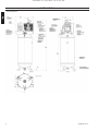 4
4
-
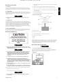 5
5
-
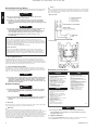 6
6
-
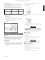 7
7
-
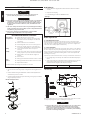 8
8
-
 9
9
-
 10
10
-
 11
11
-
 12
12
-
 13
13
-
 14
14
-
 15
15
-
 16
16
-
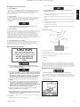 17
17
-
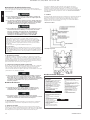 18
18
-
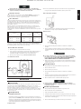 19
19
-
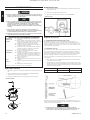 20
20
-
 21
21
-
 22
22
-
 23
23
-
 24
24
-
 25
25
-
 26
26
-
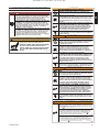 27
27
-
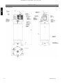 28
28
-
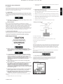 29
29
-
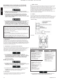 30
30
-
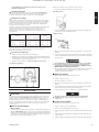 31
31
-
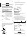 32
32
-
 33
33
-
 34
34
-
 35
35
-
 36
36
-
 37
37
-
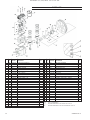 38
38
-
 39
39
-
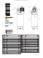 40
40
-
 41
41
-
 42
42
-
 43
43
-
 44
44


Ingersoll Rand SS4L5 Single-Stage Twin Cylinder Pro Air Compressor, 5 HP, 230V, 135 PSI, 60 Gallons Le manuel du propriétaire
- Catégorie
- Compresseurs d'air
- Taper
- Le manuel du propriétaire