Day-Brite CFI HCY LED High Bay Install Instructions
- Taper
- Install Instructions

7/16/2021
13 LED High Bay Light,14000-21000lm,4000K/5000K,120-347V
14 LED High Bay Light,28000-33000lm,4000K/5000K,120-347V
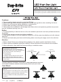
Cautions:
Attention:
BLACK/BROWN WHITE/BLUE
YELLOW/GREEN
DIM+
DIM-
AUX+
AB
AC Line AC Neutral BLACK/BROWN WHITE/BLUE
AC Line AC Neutral
GND
YELLOW/GREEN
GND
As for the wire color of DIM+,DIM-
and AUX+, pls check the light label.
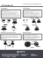
1. Screw the hook into the fixture, tighten and fix it.
(figure 1)
2. Hang the fixture on the ceiling hook or chain. (figure 2)
3. After installation, connect the wire of the fixture to the
mains according to local wiring rules, ensure the
connection is stable and make good protection on the
connection.
Hook Mount:
Notice:
1. To avoid possibility of electrical shock or fire, the installation personnel must have professional electric
knowledge.
2. Please wear gloves to avoid injury before installation.
3. If any smoke or spark of the wire happened, please turn off the power immediately and notify relevant
personnel.
4. Please use listed water proof strain relief bushing when connecting the supply cord to the outlet box.
1. Can not use the electric generator to test the LED light.
2. Please abide by related country, regional and local law and regulations when installing this fixture.
3. Please turn off the power before installation or maintenance.
4. Proper earth grounding is required to ensure safety.
5. This product is not suitable for cold storage areas where obvious temperature gradients are present,
such as ventilation opening, door, etc.
1. Please check if there is any damage during shipping. If so, please contact manufacturer timely.
2. Please read the installation instruction carefully to check whether all the accessories are complete.
3. After confirmation, then install the fixture according to installation steps.
Wiring Diagram & Instruction:
This led highbay light can be equipped with
optional DC motion sensor, and is available with
0-10V dimming function, with following 3
dimming solutions:
1. 0-10V dimming,
2. Intelligent dimming with DC motion sensor,
3. Pre-install tool-free handling DC motion
sensor dimming module, and choose dimming
function freely.
Installation Methods: Hook Mount, Ceiling Mount, 1/2"NPT Mount.(Please choose the
most suitable installation method for the purchased product as per your needs)

7/16/2021
13” LED High Bay Light,14000-21000lm,4000K/5000K,120-347V
14” LED High Bay Light,28000-33000lm,4000K/5000K,120-347V
1. Mark with a mark pen or sharp tool on the mounting
surface and drill. (figure 3)
2. Fix screws into the holes with a hammer. (figure 4)
3. Align the bracket hole with screw hole (figure 5), and
push the fixture to one side (figure 6) and fix it.
4. After installation, connect the wire of the fixture to the
mains according to local wiring rules, ensure the connection
is stable and make good protection on the brackets screws,
users can adjust 50° to the left or right vertically. (figure 7)
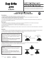
1. Unscrew the nuts on 1/2" NTP.(figure 8)
2. Insert 1/2" NTP stem into the bracket hole. (figure 9)
3. Re-screw the nuts. (figure 10)
4. After installation, connect the wire of the fixture to the
mains according to local wiring rules, ensure the
connection is stable and make good protection on the
connection. By adjusting the brackets screws, users can
adjust 50° to the left or right vertically. (figure 11)
Ceiling Mount:
Installation of DC motion sensor
1/2"NPT Mount
The fixture has integrated function of 2 CCT selectable
and 2 Power selectable. The setting could be
customized. Operation: Take away the water-proof
gasket, adjust dip switch to choose CCT and Power as
per sign. The original setting could be either as factory
default or customized request(Figure 12-2).
Optional Function
Figure 8
Figure 9
Figure 10 Figure 11
Figure12-1. If fixture has sensor receptacle installed, screw the
1/2'' knockout out with screw driver by illustrated direction, and
screw the sensor kit on. The sensor is set as universal
mode(refer to sensor spec sheet), the setting is program mable
via remote control(the remote control is not included in
standard packing)
Figure 12-1
D/Detail

7/16/2021
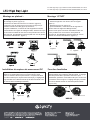
Précautions :
Schéma de câblage et instructions :
AB
BLACK/BROWN WHITE/BLUE
AC Line AC Neutral
YELLOW/GREEN
GND
BLACK/BROWN WHITE/BLUE
YELLOW/GREEN
DIM+
DIM-
AUX+
AC Line AC Neutral
GND
As for the wire color of DIM+,DIM-
and AUX+, pls check the light label.
Crochet de montage :
1. Impossible d'utiliser le générateur électrique pour tester la lumière LED.
2. Veuillez respecter les lois et réglementations nationales, régionales et locales lors de l'installation de ce luminaire.
3. Veuillez couper l'alimentation avant l'installation ou la maintenance.
4. Une mise à la terre appropriée est requise pour assurer la sécurité.
5. Ce produit n'est pas adapté aux zones de stockage frigorifique où des gradients de température évidents sont présents, tels
que l'ouverture de ventilation, la porte, etc.
Remarquer:
1. Pour éviter tout risque de choc électrique ou d'incendie, le personnel d'installation doit connaissances électriques.
2. Veuillez porter des gants pour éviter les blessures avant l'installation.
3. En cas de fumée ou d'étincelle du fil, veuillez couper immédiatement l'alimentation et notifier
personnels concernés.
4. Veuillez utiliser une bague de décharge de traction étanche à l'eau lors de la connexion du cordon d'alimentation à la boîte de
sortie.
1. Veuillez vérifier s'il y a des dommages pendant l'expédition. Si tel est le cas, veuillez contacter le fabricant en temps opportun.
2. Veuillez lire attentivement les instructions d'installation pour vérifier si tous les accessoires sont complets.
Après confirmation, installez le luminaire selon les étapes d'installation.
Attention:
Ce luminaire led highbay peut être équipé de capteur de
mouvement DC en option, et est disponible avec fonction de
gradation 0-10V, avec 3 gradations suivantes solutions:
1. gradation 0-10V,
2. Gradation intelligente avec capteur de mouvement DC,
3. Pré-installation du mouvement DC sans outil module de
gradation du capteur et choisissez la gradation
fonctionner librement.
1. Vissez le crochet dans le luminaire, serrez et fixez-le.
(Figure 1)
2. Accrochez le luminaire au crochet ou à la chaîne du
plafond. (Figure 2)
3. Après l'installation, connectez le fil du luminaire au
secteur conformément aux règles de câblage locales,
assurez-vous que le la connexion est stable et assure une
bonne protection sur le lien.
Méthodes d'installation: montage sur crochet, montage au plafond, montage 1/2 "NPT. (Veuillez choisir le méthode
d'installation la plus appropriée pour le produit acheté selon vos besoins)
13 LED High Bay Light,14000-21000lm,4000K/5000K,120-347V
14 LED High Bay Light,28000-33000lm,4000K/5000K,120-347V

7/16/2021
1. Marquez avec un marqueur ou un outil pointu sur la surface
de montage et percer. (figure 3)
2. Fixez les vis dans les trous avec un marteau. (figure 4)
3. Alignez le trou du support avec le trou de vis (figure 5) et
poussez le fixation de côté (figure 6) et fixez-la.
4. Après l'installation, connectez le fil de l'appareil au secteur
conformément aux règles de câblage locales, assurez-vous que
la connexion est stable et faire une bonne protection sur les vis
des supports, les utilisateurs peuvent ajuster 50° vers la gauche
ou la droite verticalement. (figure 7)
1. Dévisser les écrous sur 1/2" NTP.(figure 8)
2. Insérez la tige NTP 1/2" dans le trou du support.
(figure 9)
3. Revissez les écrous. (figure 10)
4. Après l'installation, connectez le fil de l'appareil au
secteur selon les règles de câblage locales,
assurez-vous que la connexion est stable et faire une
bonne protection sur la connexion. En ajustant le
supports vis, les utilisateurs peuvent régler 50° vers la
gauche ou la droite verticalement. (figure 11)
Montage au plafond :
Installation du capteur de mouvement DC
Montage 1/2"NPT
Le luminaire a une fonction intégrée de 2 CCT
sélectionnables et 2 Puissance sélectionnable. Le réglage
peut être personnalisé. Opération: Enlevez le joint
d'étanchéité, ajustez le commutateur DIP pour choisir CCT
et puissance selon le signe. Le réglage d'origine peut être
soit comme défaut d'usine ou demande personnalisée
(Figure 12-2).
Fonction facultative
Figure 8
Figure 9
Figure 10 Figure 11
Figure12-1. Si le luminaire a un réceptacle de capteur installé,
vissez le 1/2'' défonçable avec un tournevis dans le sens
illustré, et vissez le kit de capteur activé. Le capteur est défini
en mode universel (voir capteur fiche technique), le réglage est
programmable via la télécommande (le la télécommande n'est
pas incluse dans l'emballage standard)
Figure 12-1
débouchure 1/2"
kit de capteur
D/Detail
CCT sélectionnable
Puissance sélectionnable
13” LED High Bay Light,14000-21000lm,4000K/5000K,120-347V
14” LED High Bay Light,28000-33000lm,4000K/5000K,120-347V
-
 1
1
-
 2
2
-
 3
3
-
 4
4


Day-Brite CFI HCY LED High Bay Install Instructions
- Taper
- Install Instructions
dans d''autres langues
- English: Day-Brite CFI HCY LED High Bay
Documents connexes
Autres documents
-
Lightolier IHB Series Decorative High Bay Manuel utilisateur
-
Stonco Garage and Canopy DualSelect Install Instructions
-
Warehouse Lighting WAREHOUSE-LIGHTING Adjustable Linear High Bay Manuel utilisateur
-
-
Juno RB4 SWW5 RetroBasics 4 Inch Switchable White LED Manuel utilisateur
-
 ASD ASD-SFL2040 Manuel utilisateur
-
Halo HLA406FL9FS1EMWR Mode d'emploi
-
-
-
NOTHING BUT LEDS BLT-CHB04B-100WBCA1-W50K Manuel utilisateur
