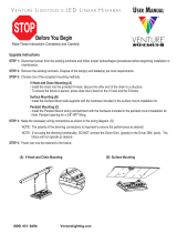
Warehouse Lighting WAREHOUSE-LIGHTING Adjustable Linear High Bay Manuel utilisateur

Taper
Manuel utilisateur
CAUTION:
1. Read all instructions before starting installation.
2. This product must be installed in accordance with the applicable
installation codes by a qualified electrician familiar with the
construction and operation of the product and the hazards involved.
3. Disconnect power at circuit breaker of fuse before starting installation.
4. To avoid injury, wear gloves during installation.
5. To reduce the risk of electrical shock and product damage, do not
install this luminaire during rain or other storms.
6. Do not test luminaire using an electric generator before installation.
Instructions:
ADJUSTABLE LINEAR HIGH BAY
INSTALLATION INSTRUCTIONS
Wiring Diagram
S
S
S
For dimming wires, use class 1 wiring methods.
Cap dimming wires (separately) if not used.
upply Line Black Wire
Luminaire
upply Neutral White Wire
upply Ground Green/ Bare Wire
Violet Wire
0-10V Dim + (pos) 0-10V Dim - (neg)
SAVE THESE INSTRUCTIONS
Chain Mount:(included)
To suspend the highbay luminaire from chains, attach the enclosed v-
hooks to the holes on the end caps. Attach the chain to a secure, stationary
structure, and use the spring clips on the end to attach the chain to the v-
hooks. Choose the appropriate knock out, and wire the fixture in
accordance with proper code. (Figure 1)
Figure 1
Wire Guards:(purchase seperately)
To attach wire guards to the luminaire, snap onto the
adjustable head overtop of the lenses.
Light DirectionAdjustment:
After the fixture is installed, adjust the lighting direction
of the module according to yourneeds (145° maximum
adjustment from left to right).
Grey or Pink Wire
Cable Mount:(purchase seperately)
To suspend the highbay luminaire from cables, slide the button stop attached
to the end of the cable kit through the hole in the end cap. Then, slide the
rectangular plate installed on the cable through the same hole. Attach the
cable to a secure, stationary structure. Use the spring slide to adjust the
height. Choose the appropriate knockout, and wire the fixture in accordance
with proper code.
Surface Mount:(purchase seperately)
To surface mount the highbay luminaire, bolt the fixture brackets to the
ceiling or rail (Figure 1). Once the brackets have been properly secured,
attach the luminaire using the screws provided (Figure 2). Choose the
appropriate knockout, and wire the fixture in accordance with proper code.
Figure 1
Pendant Mount:(purchase seperately)
To pendant mount the highbay luminaire, mount the fixture brackets to
1/2”NPS (Figure 1). Once the brackets have been properly secured,
attach the fixture using the screws provided (Fixture 2). Choose the
appropriate knockout, and wire the fixture in accordance with proper
code. Secure the cover plates to the bracket using the screws provided.
Figure 1
Figure 2
Motion Sensor/PIR Sensor:(purchase seperately)
To install motion/PIR sensor, first open the driver cover by removing the
screws (Figure 1). Using the knock out on the side cover, mount the
sensor, and make wire connections in accordance with code (Figure 2).
Once the wiring is complete, reattach the driver cover (Figure 3).
Figure 1
Figure 2
Figure 3
Figure 2
CAUTION:
1. Lisez toutes les instructions avant de commencer l’installation.
2. Ce produit doit être installé conformément à la les codes
d’installation par un électricien qualifié familier avec le la
construction et l’exploitation du produit et les dangers encourus.
3. Débranchez l’alimentation au disjoncteur du fusible avant de
commencer l’installation.
4. Pour éviter les blessures, portez des gants pendant l’installation.
5. Pour réduire le risque de choc électrique et de dommages au
produit, ne pas installer ce luminaire pendant la pluie ou d’autres
tempêtes.
6. Ne testez pas le luminaire à l’aide d’un générateur électrique avant
l’installation.
Instructions:
BAIE HAUTE LINÉAIRE GLABLE
INSTRUCTIONS D’INSTALLATION
Diagramme de
blage
S
S
S
Pour les fils de gradaon, u�lisez des
méthodes de câblage de classe 1.bler les
fils de gradaon (séparément) sil n’est pas
u�lisé.
upply Line Black Wire
Luminaire
upply Neutral White Wire
upply Ground Green/ Bare Wire
Violet Wire
0-10V Dim + (pos) 0-10V Dim - (neg)
ENREGISTRER CES INSTRUCTIONS
Mont de chaîne:(Inclus)
Pour suspendre le luminaire highbaydes chaînes, attachez les crochets v-
joints aux trous sur les bouchons d’extrémité. Attachez la chaîne à une
structure fixe et sécurisée et utilisez les pinces à ressorts à l’extrémité pour
attacher la chaîne aux crochets en V. Choisissez le knock out approprié, et
le fil de l’appareil conformément au code approprié. (Figure 1)
Figure 1
Gardes de fil:(acheter séparément)
Pour attacher des garde-fils au luminaire, accrochez-
vous à la tête réglable des lentilles.
Réglage de la direction de la lumière:
Une fois l’appareil installé, réglez la direction
d’éclairage du module en fonction de vos besoins
(réglage maximum de 145° de gauche à droite).
Grey or Pink Wire
Câble:(acheter séparément)
Pour suspendre le luminaire highbaydes câbles, faites glisser l’arrêt du
bouton attac à l’extrémité du kit de câble à travers le trou dans le bouchon
d’extrémité. Ensuite, faites glisser la plaque rectangulaire installée sur le
câble à travers le même trou. Attachez le câble à une structure fixe et fixe.
Utilisez la lame de ressort pour ajuster la hauteur. Choisissez le knock-out
approprié, et le fil de l’appareil conformément au code approprié.
Mont de surface:(acheter séparément)
Pour monter à la surface le luminaire highbay, boulonner les supports
d’appareil au plafond ou au rail (figure 1). Une fois que les supports ont été
correctement fixés, attachez le luminaire à l’aide des vis fournies (figure 2).
Choisissez le knock-out approprié, et le fil de l’appareil conformément au
code approprié.
Figure 1
Support pendentif:(acheter sépament)
Pour monter le luminaire highbay, monter les supports d’appareil à
1/2"NPS (figure 1). Une fois que les supports ont été correctement fixés,
attachez l’appareil à l’aide des vis fournies (Montage 2). Choisissez le
knock-out approprié, et le fil de l’appareil conformément au code
approprié. Fixer les plaques de couverture sur le support à l’aide des vis
fournies.
Figure 1
Figure 2
Capteur de mouvement/Capteur PIR:
(acheter parément)
Pour installer le capteur de mouvement/PIR, ouvrez d’abord le
couvercle du conducteur en enlevant les vis (figure 1). À l’aide du
knock-out sur le couvercle latéral, montez le capteur et faites des
connexions de fil conformément au code (figure 2). Une fois le câblage
terminé, rattacher le couvercle du conducteur (figure 3).
Figure 1
Figure 2
Figure 3
Figure 2
  • Page 1 1
  • Page 2 2
  • Page 3 3
  • Page 4 4

Warehouse Lighting WAREHOUSE-LIGHTING Adjustable Linear High Bay Manuel utilisateur

Taper
Manuel utilisateur