Sunex Tools 8400 Le manuel du propriétaire
- Catégorie
- Supports de sol à panneau plat
- Taper
- Le manuel du propriétaire

8400 1 rev. 03/17/15
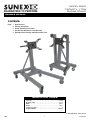
Capacity ..................................... 1 Ton
Overall Length .................................41.7"
Width . . . . . . . . . . . . . . . . . . . . . . . . . . . . . . . . . . . . . . . . .28.5"
Height . . . . . . . . . . . . . . . . . . . . . . . . . . . . . . . . . . . . . . . .33.1"
Locking Positions ..................................8
Shipping Weight ............................. 121 lbs.
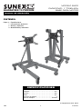
SPECIFICATIONS
OWNER'S MANUAL
MODEL 8400
CAPACITY: 1TON
ENGINE STAND
CONTENTS:
Page 1 Specifications
2 Warning Information
3 Setup, Operating Instructions
4 Preventative Maintenance and Warranty
5 Exploded View Drawing and Replacement Parts
© Copyright 2015, Sunex Tools®
GUARANTEED TO PERFORM

8400 2 rev. 03/17/15
WARNINg INFORMATION
This is the safety alert symbol. It is used to alert you
to potential personal injury hazards. Obey all safety
messages that follow this symbol to avoid possible
injury or death.
IMPORTANT: READ THESE INSTRUCTIONS BEFORE OPERATING
BEFORE USING THIS DEVICE, READ THIS MANUAL COMPLETELY AND THOROUGHLY, UNDERSTAND ITS OPERATING
PROCEDURES, SAFETY WARNINGS AND MAINTENANCE REQUIREMENTS.
It is the responsibility of the owner to make sure all personnel read this manual prior to using the device. It is also the responsibility of
the device owner to keep this manual intact and in a convenient location for all to see and read. If the manual or product labels are lost
or not legible, contact Sunex® for replacements. If the operator is not fluent in English, the product and safety instructions shall be
read to and discussed with the operator in the operator's native language by the purchaser/owner or his designee, making sure that
the operator comprehends its contents.
THE NATURE OF HAZARDOUS SITUATIONS
The use of portable automotive lifting and support devices is subject to certain hazards that cannot be prevented by mechanical
means, but only by the exercise of intelligence, care, and common sense. It is therefore essential to have owners and personnel
involved in the use and operation of the equipment who are careful, competent, trained, and qualified in the safe operation of the
equipment and its proper use. Examples of hazards are dropping, tipping or slipping of loads caused primarily by improperly securing
loads, overloading, off-centered loads, use on other than hard level surfaces, and using equipment for a purpose for which it was not
designed.
METHODS TO AVOID HAZARDOUS SITUATIONS
• Read,study,understandandfollowallinstructionsbeforeoperatingthisdevice.
• UserandbystandersmustweareyeprotectionthatmeetsANSIZ87.1andOSHAstandards.
• Inspecttheenginestandbeforeeachuse.Donotuseifdamaged,altered,modied,inpoorcondition,orhaslooseormissing
hardware or components. Take corrective action before using the engine stand.
• Donotuse(ormodify)thisproductforanyotherpurposethanthatforwhichitwasdesignedwithoutconsultingthe
manufacturer's authorized representative. No alterations should be made to this product.
• Donotusebeyondratedcapacity.
• Useonlyonhardlevelsurfacecapableofsupportingtheload.
• Lockmountingplaterotatingmechanismbeforeapplyingaload.
• Makesureallmountinghardwareissecurelytightenedandsetupisstablebeforerotatingengine.
• AlwaysusehighstrengthSAEgrade8boltsformountingenginetomountingheadngers.
• Makesurewidestsetofmountingheadngersarenearestthegroundwhenmountingenginetostand.
• Assuretheloadiscentered,balancedandsecuredtothemountingheadandngers.Theengine’sweightshouldbebalanced
withinoneinchofthemountinghead’srotationalaxis.
• Releaserotationallockingdeviceslowlyandcarefully.Offcenterloadmaymaketheloadandhandlerotateineitherdirection
when the rotational locking device is released.
• Rotatetheengineusingthehandleordeviceprovided.
• Lockthewheelsand/orcastersbeforeworkingontheengine.
• Adequatelysupportthevehiclebeforestartingrepairs.
• Neverloosenmountingheadboltsorenginemountingboltsunlessengineissupportedbyacraneorhoist.
• Onlyattachmentsand/oradapterssuppliedbySunex® shall be used.
• Donotusestandtodollyortransportengine.
• Donotcrawlunderengineorplaceanypartofyourbodyunderengineatanytime.
• Refertoenginemanufacturer’sservicemanualforproperliftingpoints,mountingpointsandboltsizes.Mountingboltsshould
be torqued at appropriate amount to maintain load.
• ThisproductmaycontainoneormorechemicalsknowntotheStateofCaliforniatocausecancerandbirthdefectsorother
reproductive harm.
Wash hands thoroughly after handling.
• Failuretoheedthesewarningsmayresultinseriousorfatalpersonalinjuryand/orpropertydamage.
WARNING: Indicates a hazardous situation
which, if not avoided, could result in death
or serious injury.
WARNING
WARNING
WARNING

8400 3 rev. 03/17/15
OWNER'S MANUAL
WARNING
CONSEQUENCES OF NOT AVOIDING HAZARDOUS SITUATIONS
Failure to read this manual completely and thoroughly, failure to understand its OPERATING INSTRUCTIONS, SAFETY WARNINGS,
MAINTENANCEINSTRUCTIONSandcomplywiththem,andfailuretocomplywiththeMETHODSTOAVOIDHAZARDOUSSITUATIONScould
cause accidents resulting in serious or fatal personal injury and/or property damage.
SETUP
PLEASE REFER TO THE EXPLODED VIEW DRAWING IN THIS MANUAL IN ORDER TO IDENTIFY PARTS.
1. Install the front wheels(#25)inthefrontofleft(#23)andrightlegs(#24)withthebolts(#16),washers(#17)andnuts(#13)provided.
2.Assemblethemiddleswivelcasters(#1)tothebottomframe(#7)withthebolts(#15)andnuts(#6)andtighten.
3.Assembletherearswivelcasters(#3)tothebottomframe(#7)withthebolts(#4),springwashers(#5)andnuts(#6)andtighten.
4.Looselyassembletheuprightmast(#11)tothebottomframe(#7)withthebolts(#12)andnuts(#13).Makesuretheextendedendofthe
receivertubeatthetopoftheuprightmastispointingtowardthefrontofthelegs(#23)and(#24).
5.Looselyassembleoneendofmastbraces(#9)totheinboardsidesoftheframesidetubeswiththebolts(#8)andnuts(#13).Loosely
assembletheoppositeendsofthemastbraces(#9)totheuprightmast(#11)withthebolt(#8)andnut(#13).Tightenallhardware
mentioned in steps 4 and 5.
6.Alignthetwoholesinthelegs(#23)and(#24)withthecorrespondingholesinthebottomframe(#7)andsecurethenintheframewiththe
pins(#2)andR-Clips(#14).Makesuretoputtheleftandrightlegsintheintendedsidesofthebottomframe(#7).
7.Installthetubeoftherotatingplate(#20)inthetoptubeoftheuprightmast(#11)andlockitinplacewiththepin(#10).
8.Securethengers(#18)totherotatingplate(#20)byinsertingthebolts(#19)withwashers(#26)throughtheloopsinthengersandthen
passingtheboltsthroughtheholesintheplate(#20).Securetheboltstotheplatewiththewashers(#17)andnuts(#13).
9.Installthehandle(#22)throughtheholesintherotatingplatetube(#20)andsecureitbypushingonthehandlecap(#21)onthehandle.
OPERATING INSTRUCTIONS
This is the safety alert symbol used for the OPERATING INSTRUCTIONS section of this manual to alert you to potential personal
injury hazards. Obey all instructions to avoid possible injury or death.
1. Consult the vehicle or engine manufacturer for service manuals and/or technical bulletins that provide information on suggested
engine mounting tips, proper size and type mounting bolts and the engine's center of balance. The engine's center of balance will
have to be aligned with the rotational axis of the engine stand's mounting head.
2. Drain oil and coolant and remove clutch bell housing and flywheel from engine before mounting. Attach an engine lifting bar or sling
to the engine and secure the bar or sling to a shop crane or hoist. Slowly lift the engine from its compartment, making sure no other
vehicle components, wires or hoses obstruct the free movement of the engine. Raise the engine high enough so its center of
balance is close to the rotational axis of the stands's mounting head.
3. Make sure the four mounting head fingers are loosely connected to the mounting head plate. Secure the four mounting head fingers
to the bell housing end of the engine with the appropriate bolts and washers. Reposition the mounting head, fingers and engine so
the engine's center of balance is within one inch of the mounting head's rotational axis. Tighten all bolts to a sufficient torque
requirement that prevents any slippage.
4. Slowly lower the crane or hoist so the engine stand supports full weight of the engine. To check engine balance and secure setup
of the engine to the stand, slowly rotate the engine by turning the handle. If balance or setup are not stable, rotate the engine to its
original position, raise the crane or hoist so the weight of the engine is removed from the stand and make the correct adjustments.
After adjustments are made, tighten all bolts. This adjustment procedure may have to be duplicated several times until correct.
After the setup is balanced and secure, the lifting bar or sling can be removed from crane or hoist.
5. To remove the engine from the stand, connect the lifting bar or sling to the crane or hoist and raise the engine high enough to take
the weight off the stand. Carefully remove the bolts that connect the four mounting fingers to the engine. Be aware there will be a
slight movement of stand as total engine weight is transferred to crane or hoist.
MODEL 8400
CAPACITY: 1TON
ENGINE STAND
GUARANTEED TO PERFORM

8400 4 rev. 03/17/15
SUNEXINTERNATIONAL,INC.WARRANTSTOITSCUSTOMERSTHATTHECOMPANY’SSUNEXTOOLS®BRANDED
PRODUCTSAREFREEFROMDEFECTSINWORKMANSHIPANDMATERIALS.
Sunex International, Inc. will repair or replace its Sunex Tools® branded products which fail to give satisfactory service due to defective workmanship or materials, based
upon the terms and conditions of the following described warranty plans attributed to that specific product.
This product carries a ONE-YEAR warranty. During this warranty period, Sunex Tools will repair or replace at our option any part or unit which proves to be defective in
material or workmanship.
Otherimportantwarrantyinformation
This warranty does not cover damage to equipment or tools arising from alteration, abuse, misuse, damage and does not cover any repairs or replacement made by
anyone other than Sunex Tools or its authorized warranty service centers. The foregoing obligation is Sunex Tools’ sole liability under this or any implied warranty and
under no circumstances shall we be liable for any incidental or consequential damages.
Note:
Some states do not allow the exclusion or limitation of incidental or consequential damages, so the above limitation or exclusion may not apply to you.
Return equipment or parts to an authorized service center, transportation prepaid. Be certain to include your name and address, evidence of the purchase date, and
description of the suspected defect. If you have any questions about warranty service, please write to Sunex Tools. This warranty gives you specific legal rights and you
may also have other rights which vary from state to state.
Repair kits and replacement parts are available for many of Sunex Tools products regardless of whether or not the product is still covered by a warranty plan.
SHIPPINGADDRESS:
Sunex Tools
315 Hawkins Rd.
Travelers Rest, South Carolina 29690
MAILINGADDRESS:
Sunex Tools
P.O. Box 1233
Travelers Rest, South Carolina 29690
LIMITED WARRANTY
PREVENTATIVE MAINTENANCE
This is the safety alert symbol used for the PREVENTATIVE MAINTENANCE section of this manual to alert you to potential personal
injury hazards. Obey all instructions to avoid possible injury or death.
1. Always store the engine stand in a well protected area where it will not be exposed to inclement weather, corrosive vapors, abrasive dust,
or any other harmful elements. The engine stand must be cleaned of water, snow, sand, grit, oil, grease or other foreign matter before
using.
2. Lubricate the wheels, casters, zerk fittings, gear and rotating shaft with a general purpose grease.
3. Every engine stand owner is responsible for keeping the engine stand label clean and readable. Use a mild soap solution to wash the
externalsurfacesofthestand.ContactSunexforareplacementlabelifyourstand’slabelisnotreadable.
4. Inspect the stand before each use. Do not use the stand if any component is cracked, broken or bent. Do not use the stand if it has loose
or missing hardware or components, or is modified in any way. Take corrective action before using the stand again.

8400 5 rev. 03/17/15
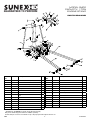
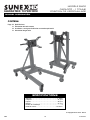
PARTS DRAWINg
*HardwareKit–RS8400HK(incl#2(4),#12(2),#13(11)(4))
Only items identified by part number are available separately.
All bolts and pins need to be assembled loosely to fit properly and then tightened before use.
ITEM
NO.
PART NO. Description QTY
1 RS840001
MiddleSwivelCaster(incl#2,#6,)
2
2 RS840002 Pin 4
3 RS840003 RearSwivelCaster(incl#4,#5) 2
4 Bolt 8
5 Spring Washer 8
6Nut 16
7 Bottom Frame 1
8 Bolt 3
9Mast Brace 2
10 RS840010 Pin 1
11 Upright Mast 1
12 Bolt 2
13 Nut 11
14 R-Clip 4
ITEM
NO.
PART NO. Description QTY
15 Bolt 8
16 Bolt 2
17 Washer 4
18 RS840018 FingerKit(incl#13,#17,#19) 4
19 Bolt 4
20 Rotating Plate 1
21 Handle Cap 2
22 Handle 1
23 Left Leg 1
24 Right Leg 1
25 RS840025
FrontWheelAssembly(incl#13,#16)
2
26 Washer 2
Not Shown
RS8400PLK
Label Kit 1
MODEL 8400
CAPACITY: 1TON
ENGINE STAND
GUARANTEED TO PERFORM

8400 6 rev.03/17/15
ESPECIFICACIONES
MANUAL DE OPERATIóN
MODEL0 8400
CAPACIDAD: 1 TONELADA
BASE PARA MOTOR
CONTENIDO:
Página 6 Especicaciones
7 Información de advertencia
8 Montaje y Operación
9 MantenimientoyInformation
© Copyright 2015, Sunex Tools®
Capacidad ...............................1 Tonelada
Longitud ......................................41.7"
Anchura .......................................28.5"
Altura . . .......................................33.1"
Posiciones de bloqueo .............................8
Peso de embarque ..........................121 libras
GUARANTEED TO PERFORM

8400 7 rev. 03/17/15
INFORMACIóN DE ADvERTENCIA
Este símbolo indica una alerta de seguridad y se usa para
advertir sobre peligro de accidentes personales. Observe toda
la información de seguridad que sigue a este símbolo para
evitar la posibilidad de que ocurran lesiones o muerte.
IMPORTANTE: LEA ESTAS INSTRUCCIONES ANTES DE USAR EL DISPOSITIVO
ANTES DE USAR ESTE DISPOSITIVO, LEA ESTE MANUAL DETENIDAMENTE. PROCURE ENTENDER SUS PROCEDIMIENTOS
OPERATIVOS, ADVERTENCIAS DE SEGURIDAD Y FORMA DE MANTENIMIENTO.
El propietario es responsable de asegurarse de que todo el personal lea este manual antes de usar el dispositivo. Asimismo, es
responsabilidad del propietario mantener este manual en buenas condiciones en una ubicación conveniente para su consulta. Si las
etiquetas del manual o producto son ilegibles o no están en su lugar, deberá ponerse en contacto con Sunex® para obtenerlas gratis.
El comprador/propietario o una persona designada deberá leer y comentar el producto y las advertencias de seguridad en la lengua
materna del operario que no hable inglés fluido, a fin de asegurarse de que comprende el contenido.
NATURALEZA DE LAS SITUACIONES DE RIESGO
El uso de dispositivos automotrices portátiles de levantamiento y soporte está sujeto a ciertos peligros los que no se pueden prevenir por
medidas mecánicas, sino por el ejercicio de inteligencia, cuidado y sentido común. Por lo tanto, es esencial que el uso del dispositivo
quede en manos de los propietarios y de personal que sea cuidadoso, competente, capacitado y habilitado para realizar una operación
segura. Algunos ejemplos de peligros son dejar caer, inclinar o resbalar las cargas, principalmente como consecuencia de una sujeción
incorrecta, sobrecarga, posición no centrada, uso en superficies no niveladas o firmes, así como usar el dispositivo con un fin para el que
no está diseñado.
FORMAS DE EVITAR LAS SITUACIONES DE RIESGO
• Lea, estudie, comprenda y siga todas las instrucciones antes del uso.
• LlevepuestoproteccióndeojosquecumplaconlasnormasdeOSHAyANSIZ87.1(usuariosyespectadores).
• Inspeccionelabasedemotorantesdecadauso.Nolausesiestédañada,cambiada,modicada,enpobrescondiciones,o
si cuente con ferretería o componentes flojos o faltantes. Tome acción corrective antes de usar la base del motor.
• Nouse(nialtere)esteproductoparaningúnotrouseexceptoelparaelcualfuediseñado,sinconsultarlealrepresentante
autorizado del fabricante. No se deberá realizar ninguna modificación a este producto.
• Nouseelgatomásalládesucapacidadnominal.
• Utilicesolosobreunasupercieduraynivelada,capazdesostenerlacarga.
• Bloqueeelmecanismogiratoriodelaplacademontajeantesdeaplicarunacarga.
• Asegúresequetodalaferreteríademontajeestéapretadaseguramenteyelmontajeestésujetadoantesderotarelmotor.
• SiempreusepernosdeclasicaciónSAEdealtaresistencia(noprovistos)paramontarelmotorylosdedalesdeldelaculata.
• Asegúresequelosdedalesdelaculatademontaje(siseanprovistos)esténmáscercaalpisoalmomentodemontarelmo
tor la base.
• Asegúresequelacargaestécentrada,equilibradaysujetadaalaculatademontajeyalosdedales.Elpesodelmotordebe
estar equilibrado dentro de una pulgada del eje rotacional de la culata de montaje.
• Libereeldispositivodebloqueogiratoriolentamenteydeformacuidadosa.Unacargadescentradapodráhacerquelacargayla
manivela gire en cualquier sentido al momento de liberar el dispositivo e bloqueo giratorio.
• Gireelmotorusandolamanivelaodispositivoprovisto.
• Bloqueelasruedasy/oruedecillasantesdetrabajarenelmotor.
•
Soporte el vehículo adecuadamente antes de comenzar las reparaciones.
• Nuncaaojelospernosdelaculatademontajenilospernosdemontajedelmotoralmenosqueelmotorestésoportadopor
una grúa o montacargas.
• Sedebenusarsoloaccesoriosy/oadaptadoresprovistosporSunex®.
• Nouselabasecomodiabloniparatransportarelmotor.
• Nosearrastredebajodelmotornisitúeningunapartedelcuerpodebajodelmotorenningúnmomento.
• Consulteelmanualdeserviciodelfabricanteporlospuntosadecuadosdelevantamiento;lospuntosdemontaje;ylos
tamaños de los pernos. Los pernos de montaje deben estar ajustados a la torsión adecuada para mantener la carga.
• EsteproductopuedecontenersustanciasquímicasconsideradasporelEstadodeCaliforniacomocausantesdecáncer,de
malformaciones congénitas u otros daños en el sistema reproductivo. Lávese bien las manos después de manipular el producto.
• Hacercasoomisoaestasadvertenciaspuedeocasionarlesionespersonalespotencialesy/odañosalapropiedad.
ADVERTENCIA: Indica una situación
peligrosa que si no se evita, puede
provocar la muerte o lesiones graves.
ADVERTENCIA
ADVERTENCIA
ADVERTENCIA

8400 8 rev. 03/17/15
MANUAL DE OPERATIóN
ADVERTENCIA
CONSECUENCIAS DE NO PREVENIR LAS SITUACIONES DE RIESGO
No leer, comprender u observar todo el contenido de este manual en relación con sus INSTRUCCIONES DE USO, ADVERTENCIAS DE
SEGURIDAD y FORMA DE MANTENIMIENTO, así como desatender las FORMAS DE EVITAR LAS SITUACIONES DE RIESGO, puede provocar
accidentes que tengan como consecuencia lesiones graves, peligro de muerte o daños materiales.
MONTAJE
CONSULTE POR FAVOR EL DIBUJO DE VISTA EN DETALLE EN ESTE MANUAL PARA IDENTIFICAR LAS PARTES.
1. Instale las ruedas delanteras(#25)enlapartefrontaldelaspatasizquierdas(#23)yderechas(#24)conlospernos(#16),arandelas(#17)y
tuercas(#13)provistos.
2. Ensamblelasruedecillasgiratoriascentrales(#1)alarmazóninferior(#7)conlospernos(#15)ytuercas(#6)yapriete.
3. Ensamblelasruedecillasgiratoriastraseras(#3)alarmazóninferior(#7)conlospernos(#4),arandelasderesorte(#5)ytuercas(#6)y
apriete.
4. Ensambleojamenteelmástilvertical(#11)alarmazóninferior(#7)conlospernos(#12)ytuercas(#13).Asegúresequeelextremo
extendidoeneltuboreceptorenlapartesuperiordelmástilverticalestéapuntandohacialapartefrontaldelaspatas(#23)y(#24).
5. Ensambleojamenteunextremodelasabrazaderasdelmástil(#9)a los laterales interiores de los tubos laterales del armazón con los
pernos(#8)ytuercas(#13).Ensambleojamentelosextremosopuestosdelasabrazaderasdelmástil(#9)almástilvertical(#11)conel
perno(#8)ytuerca(#13).Aprietetodalaferreteríamencionadaenlospasos4y5.
6. Alineelosdosagujerosenlaspatas(#23)y(#24)conlosagujeroscorrespondientesenelarmazóninferior(#7)ysujételosenelarmazón
conlospasadores(#2)ypinzasenRR(#14).Asegúresedecolocarlaspatasizquierdasyderechasaloslateralesdestinadosenal
armazóninferior(#7)
7. Instaleeltuboenlaplacagiratoria#20enletubosuperiordelmástilvertical(#11)ybloquéeloensulugarconelpasador(#10).
8. Sujete los dedos (#18)alaplacagiratoria(#20)alinsertarlospernos(#19)conlasarandelas(#26)porlosanillosenlosdedosyluegoal
pasarlospernosporlosagujerosenlaplaca(#20).Sujetelospernosenlaplacaconlasarandelas(#17)ylastuercas(#13).
9. Instalelamanivela(#22)porlosagujeroseneltubodelaplacagiratoria#20ysujételaalempujarsobreeltapóndelamanivela(#21)en
la manivela.
INSTRUCCIONES DE USO
Este símbolo indica una alerta de seguridad y se utiliza en la parte de este manual que versa sobre las INSTRUCCIONES DE USO,
con el fin de advertir sobre los peligros de accidentes personales. Observe todas las instrucciones para evitar lesiones o peligros
de muerte. IMPORTANTE: antes de comenzar a elevar un vehículo, consulte su manual de servicio para conocer las superficies de
elevación recomendadas.
1. Consulte el fabricante del vehículo o del motor por los manuales de servicio y/o los boletines técnicos los que brindan información
sobre los consejos sugeridos de montaje de motor, el tamaño adecuado y el tipo de pernos de montaje y el centro de equilibrio del
motor. El centro de equilibro del motor tendrá que estar alineado con el eje rotacional de la culata de montaje de la base del motor.
2. Vacíe el aceite y refrigerante y extraiga el cárter del embrague and y el volante del motor antes del montaje. Sujete la barra de
levantamiento del motor o eslinga al motor y sujete la barra o eslinga a una grúa de taller o montacargas. Levante lentamente el motor
de su compartimiento, asegurándose que ningún otro componente, alambre ni manguera obstruya el movimiento libre del motor. Levante
el motor lo suficiente para que su centro de equilibrio esté cerca del eje rotacional de la culata de montaje de la base.
3. Asegúrese que los cuatro dedales de la culata de montaje estén conectados flojamente a la placa de la culata de montaje. Sujete los
cuatro dedales de la culata de montaje al extremo del cárter del motor con los pernos y arandelas adecuados. Recoloque la culata de
montaje, los dedales y el motor con el fin de que el centro de equilibrio esté dentro de una pulgada del eje rotacional de la culata de
montaje. Apriete todos los pernos al requisito de torsión suficiente para prevenir cualquier deslizamiento.
4. Baje la grúa o montacargas lentamente para que la base del motor soporte el peso completo del motor. Para verificar el equilibrio del
motor y sujetar el montaje del motor a la base, gire el motor lentamente al girar la manivela. Si el equilibrio o el montaje no esté estable,
gire el motor a su posición original, levante la grúa o montacargas para que el peso del motor esté alejado de la base y realice los ajustes
correctos. Después de realizar los ajustes, apriete todos los pernos. Quizás sea necesario duplicar este procedimiento de ajuste varias
veces hasta que esté correcto. Después de que el montaje esté estable y seguro, la barra de levantamiento o eslinga puede extraerse de
la grúa o montacargas.
5. Para extraer el motor de la base, conecte la barra de levantamiento o eslinga a la grúa o montacargas y levante el motor lo
suficientemente alto para aliviar el peso de la base. Extraiga los pernos cuidadosamente, los que conectan los cuatro dedales de
montaje al motor. Esté consciente que habrá un movimiento ligero de la base ya que el peso integral del motor será transferido a la
grúa o montacargas.
MODEL0 8400
CAPACIDAD: 1 TONELADA
BASE PARA MOTOR
GUARANTEED TO PERFORM

8400 9 rev.03/17/15
SUNEXINTERNATIONAL,INC.,LEGARANTIZAASUSCLIENTESQUELASHERRAMIENTASYPRODUCTOSCON
LAMARCADELAEMPRESASUNEXTOOLS®NOCONTIENENDEFECTOSENSUMANODEOBRANIMATERIAS
PRIMAS
.
Sunex International, Inc., reparará o sustituirá sus productos con la marca Sunex Tools® que reflejen fallas en el funcionamiento satisfactorio
debido a que la mano de obra o las materias primas estén defectuosas, tomando como base las cláusulas y condiciones de los planes de
garantía descritos a continuación y asignados a ese producto específico. Este producto tiene una garantía de UN AÑO
. Durante este periodo
de garantía, Sunex Tools
®
reparará o repondrá, a nuestra opción, cualquier parte o unidad la cual demuestra ser defectuosa en cuanto a
material o mano de obra.
Otraimportanteinformacióndelagarantía:
Esta garantía no cubre daños a equipo o herramientas debido a modificaciones, abuso, mal uso o daños y no cubre ninguna reparación o
sustitución hecha por ninguna persona que no sea Sunex Tools
®
o alguno de sus centros de servicio de garantía autorizados.
La obligación
antes mancionada queda bajo la responsabilidad exclusiva de Sunex Tools® según se menciona o de cualquier garantía implícita y
bajo ninguna circunstancia quedará bajo su responsabilidad cualquier garantía implícita ya bajo ninguna circunstancia quedará bajo su
responsabilidad cualquier daño incidental o consecuencial.
NOTA:
Algunos estados no permiten la exclusión ni limitación de daños. Devuelva el equipo o partes a un centro de servicio autorizado, con el
flete prepagado. Asegúrese de incluir su nombre y dirección, comprobación de la fecha de compra, y la descripción del defecto sospechado.
Si usted tiene alguna pregunta acerca del servicio de garantía, escriba por favor a Sunex Tools
®
. Esta garantía le brinda derechos legales
específicos y usted puede contar con derechos adicionales los cuales varían de estado a estado. Están disponibles equipos de reparación y
partes de sustitución para muchos de los productos de Sunex Tools
®
, independientemente del hecho de que el producto aún esté cubierto o
no por un plan de garantía
DIRECCIóNAEMBARCARSE:
Sunex Tools
315 Hawkins Rd.
TravelersRest,SouthCarolina29690
DIRECCIóNDECORREOS:
Sunex Tools
P.O. Box 1233
TravelersRest,SouthCarolina29690
gARANTÍA LIMITADA:
MANTENIMIENTO DE SEGURIDAD
Este símbolo indica una alerta de seguridad y se utiliza en la parte de este manual que versa sobre el MANTENIMIENTO DE
SEGURIDAD, con el fin de advertir sobre los peligros de accidentes personales. Observe todas las instrucciones para evitar
lesiones o peligros de muerte.
1. Siempre almacene las bases en un área bien protegida donde éstas no estarán expuestas a las inclemencias del tiempo, vapores
corrosivos, el polvo abrasivo o cualquier otro elemento dañino. Antes de usar, compruebe que el gato no contenga restos de agua, nieve,
arena o arcilla.
2. La base debe ser lubricada periódicamente con el fin de prevenir la corrosión y el desgaste prematuro de las partes.
3. Cada propietario de una base de gato es responsable por mantener limpias y legibles las etiquetas de la base Use una solución de jabón
suave para limpiar las superficies externas de la base. Comuníquese con Sunex para una etiqueta de repuesto si la etiqueta de su base
no es legible.
4. Inspeccione las bases antes de cada uso. No use las bases de soporte si cualquier componente esté agrietado, roto, o doblado. No
use la base si cuenta con ferretería o componentes flojos o faltantes, o si ésta haya sido modificada de cualquier forma. Tome acciones
correctivas antes de usar la base de nuevo. El desgaste prematuro o daños a los componentes ocasionados por ferretería floja o faltante
no son elegibles para consideraciones de garantía.

8400 10 rev. 03/17/15
Capacité ................................... 1 Tonne
Longueur ....................................41,7 po
Largeur .....................................28,5 po
Hauteur .....................................33,1 po
Position de verrouillage .............................8
Poids du moteur ............................121 livres
SPÉCIFICATIONS
MANUEL D'OPERATIóN
MODÈLE 8400
CAPACITÉ : 1 TONNE
POSITION DE VERROUILLAGE
CONTENU:
Page 10 Spécifications
11 Information d'avertissement
12 Installation , consignes d'utilisation et entretien préventifs
13 Information de garantie
© Copyright 2015, Sunex Tools®
GUARANTEED TO PERFORM

8400 11 rev. 03/17/15
INFORMATION D' AvERTISSEMENT
IMPORTANT : LIRE CES CONSIGNES AVANT L'UTILISATION.
PRIÈRE DE LIRE CES CONSIGNES ATTENTIVEMENT ET DE S'ASSURER DE BIEN COMPRENDRE LES PROCÉDURES D'UTILISATION, LES AVER-
TISSEMENTS DE SÉCURITÉ ET LES BESOINS EN MATIÈRE D'ENTRETIEN DE L'OUTIL AVANT DE L'UTILISER.
Le propriétaire doit s'assurer que tous les employés lisent ce manuel avant d'utiliser l'outil. Le propriétaire de l'outil doit aussi maintenir ce manuel
en bon état et le ranger dans un endroit facilement accessible à tous ceux qui doivent le lire. Si le manuel ou les étiquettes de l'outil sont perdus ou
illisibles, communiquer avec Sunex®pourobtenirunremplacement.Sil’utilisateurneparlepascourammentlefrançais,lesconsignesdesécurité
et le mode d'emploi de l'outil devront lui être lues à haute voix et être discutées avec l'utilisateur, dans sa langue maternelle, par le propriétaire/
acheteurouunepersonnedésignée,and’assurerquel’utilisateurencomprennelesbienlecontenu.
LE TYPE DE SITUATIONS DANGEREUSES
L'utilisation d'appareils de levage portatifs pour automobiles est sujet à certains dangers qui ne peuvent pas être prévenus à l'aide de
moyens mécaniques, mais seulement en faisant preuve d'intelligence, soin, et bon jugement. Il est donc essentiel que les propriétaires et
lesemployésquiutiliserontcedispositifsoientprudents,compétents,qualiésetformésàl’utilisationsécuritairedel’équipement.Desexemples
de dangers comprennent le renversement, le glissement ou la chute soudaine de la charge. Ces dangers sont principalement imputables à une
charge mal répartie, une utilisation sur une surface meuble ou inclinée, ou une utilisation à des fins autres que celles pour lesquelles le dispositif a
étéconçu.
LE TYPE DE SITUATIONS DANGEREUSES
• Lire,étudieretcomprendreetsuivretouteslesinstructionsavantl’utilisation.
•
PortezuneprotectionoculairequirépondauxnormesANSIZ87.1etdel'OSHA(utilisateuretpersonnesàproximité).
• Inspecterlesupportdemoteuravantchaqueutilisation.Nepasutilisers’ilestendommagé,altéré,modié,enmauvaisecondition
ouavecunmatérielperduoudescomposantsmanquants.Effectuerlesbonnesactionsavantd’utiliserlesupportdumoteur.
• Nepasutiliser(oumodier)ceproduitpourunusageautrequeceluipourlequelilaétéconçusansconsulterle
représentant autorisé du manufacturier. Ce produit ne devrait subir aucune altération.
• Nepasutiliserunpoidsplusélevéquelacapaciténominale.
• Utiliserseulementsurunesurfacedureetauniveauadéquatpoursupporterlacharge.
• Verrouillezlemécanismederotationdelaplaquedemontageavantd'yinstallerunecharge.
• S’assurerquelematérieldemontageestbienserréetquelesystèmeeststableavantdetournerlemoteur.
• Toujoursutiliserdesboulonstrèssolidesdegrade8(nonfournis)pourmonterlemoteuràlatêteetdoigtsdemontage.
• S’assurerquelatêteetdoigtsdemontage(sifournis)sontprèsdusolquandlemontagedemoteurestenpositiondebout.
• S’assurerquelepoidsestaucentre,équilibréetxéauxdoigtsettêtedemontage.Lepoidsdumoteurdoitêtreenéquilibre
àunpoucedel’axerotatifdelatêtedemontage.
• Desserrezledispositifdeverrouillagepivotantlentementetavecprécaution.Unechargenoncentréepeutfairepivoterlacharge
etlemanchedansunsensoudansl’autrequandledispositifdeverrouillagepivotantestdesserré.
• Faitespivoterlemoteuraumoyendumancheoududispositiffourni.
• Verrouillezlesroueset/oulesroulettesavantdetravaillersurlemoteur
•
Supporter le véhicule adéquatement avant de débuter les réparations.
• Nejamaisdesserrerlesboulonsdelatêtedemontageoulesboulonsdumoteurdemontageàmoinsquelemoteurnesoit
maintenu par une grue ou un treuil.
• Seulementdesxationset/ouadaptateursfournisparSunex® peuvent être utilisés.
• Nepasutiliserlaplateformepourtransporterlemoteur.
• Neparmarcheroumettreunepartiedevotrecorpssouslemoteuràn’importequelmoment.
• Seréféreraumanueldufabricantdumoteurpourlesbonspointsdelevage,lespointsdemontageetlestaillesdesboulons.
Les boulons de montage doivent être serrés à la bonne force pour maintenir la charge.
• Ceproduitpeutcontenirdesproduitschimiquesreconnusparl'ÉtatdelaCaliforniecommecausantlecancer,des
anomalies congénitales ou d'autres effets nuisibles sur la reproduction. Se laver minutieusement les mains après avoir
utilisé le produit.
• Lemanqued'observercesavertissementspeutavoircommeconséquencedesblessurespotentielleset/oudesdégâtsmatériels.
Ce symbole indique un danger potentiel. Il est utilisé
pour avertir l'utilisateur des risques potentiels de
blessurescorporelles.Prièrederespectertoutesles
consignes de sécurité qui suivent ce symbole afin
d'éviter les blessures ou la mort potentielles.
AVERTISSEMENT : Ce symbole
indique une situation
dangereuse qui pourrait causer
la mort ou des blessures graves
si elle n'est pas évitée.
AVERTISSEMENT
AVERTISSEMENT
AVERTISSEMENT

8400 12 rev. 03/17/15
MANUEL DU PROPRIÉTAIRE
AVERTISSEMENT
MÉTHODES POUR ÉVITER LES SITUATIONS DANGEREUSES
Lemanquementdelirecemanuelcomplètementetavecattentionetl’incompréhensiondesCONSIGNESD'UTILISATION,
AVERTISSEMENTS DE SÉCURITÉ, INSTRUCTIONS D'ENTRETIEN et de se conformer à elles, et en négligeant les MÉTHODES POUR ÉVITER DES
SITUATIONS DANGEREUSES peut causer des accidents ayant comme conséquence des blessures sérieuses ou mortelles et/ou des.
INSTALLATION
VEUILLEZ VOUS RÉFÉRER AUX SCHÉMAS DE CE MANUEL POUR IDENTIFIER LES PIÈCES
1. Installez les rouesavant(#25)àl’avantdelapattegauche(#23)etdelapattedroite(#24)aveclesboulons(#16),lesrondelles(#17)etles
écrous(#13)fournis.
2. Attachezlesroulettespivotantesdumilieu(#1)aucadreinférieur(#7)aveclesboulons(#15)etlesécrous(#6)etresserrez.
3. Attachezlesroulettespivotantesarrière(#3)aucadreinférieur(#7)aveclesboulons(#4),lesrondellesélastiques(#5)etlesécrous(#6)
et resserrez.
4. Attachez sans trop serrer le montant(#11)aucadreinférieur(#7)aveclesboulons(#12)etlesécrous(#13).Assurez-vousquel’extrémité
déployéedutuberéceptacleàl'extrémitésupérieuredumontantsoitorientéeversl’avantdespattes(#23)et(#24).
5. Attachez mais sans trop serrer une extrémitédessupportsdemontant(#9)auxcôtésintérieursdestubeslatérauxducadreavecles
boulons(#8)etlesécrous(#13).Attachezsanstropserrerlesextrémitésopposéesdecessupports(#9)aumontant(#11)avecleboulon
(#8)etl’écrou(#13).Resserreztouteslespiècesmentionnéesauxétapes4et5.
6. Alignezlesdeuxoricesdanslespattes(#23)et(#24)aveclesoricescorrespondantsdanslecadreinférieur(#7)etxez-lesdansle
cadreaveclesgoupillesdexation(#2)etlesgoupillesfendues(#14).Assurez-vousdeplacerlespattesgaucheetdroiteduboncôtédu
cadreinférieur(#7).
7. Installez le tubedelaplaquepivotante(#20)dansletubesupérieurdumontant(#11)etverrouillez-lebienenplaceaveclagoupille
dexation(#10).
8. Attachez lesbaguettes(#18)àlaplaquepivotante(#20)eninsérantlesboulons(#19)aveclesrondelles(#26)àtraverslesbouclesdans
lesbaguettespuisenpassantlesboulonsdanslesoricesdelaplaque(#20).Attachezlesboulonsàlaplaqueaveclesrondelles(#17)et
lesécrous(#13).
9. Installezlemanche(#22)àtraverslesoricesdutubedelaplaquepivotante(#20)etxez-lebienenappuyantsurlecapuchondemanche
(#21)quiestsurlemanche.
DIRECTIVES D'UTILISATION
Ce symbole sert à identifier les risques de blessures dans la rubrique MODE D'EMPLOI. Suivre les consignes afin d'éviter
les ris ques de blessure ou de mort.
1. Consulterlemanueld’entretiendufabricantdumoteurouduvéhiculeet/oulesbulletinstechniquesqui fournissent des informations sur
lesastucessuggéréessurlemontagedumoteur,surlabonnetailleetletypedesboulonsdemontageetsurlecentred’équilibredu
moteur.Lecentred’équilibredumoteurdoitêtrealignéaveclesaxesrotatifsdelatêtedemontagedelaplateformedumoteur.
2. Drainerl’huileetleliquidederefroidissement,etretirerlacloched’embrayageetlevolantdumoteuravantlemontage. Attacher la bretelle
ou la barre de levage du moteur au moteur et fixer la bretelle ou la barre à la grue ou au treuil. Soulever doucement le moteur de son
compartimentens’assurantqu’aucunautrecomposantduvéhicule,câbleoutuyaunebloquelemouvementdumoteur.Leverlemoteur
verslehautdefaçonàcequesoncentred’équilibreestprèsdel’axederotationdelatêtedemontagedelaplateforme.
3. S’assurerquelesquatredoigtsdelatêtedemontagesontlibrementconnectésàla plaque de la tête de montage. Fixer les quatre doigts
delatêtedemontageàl’extrémitédelaclochedumoteurenutilisantlesbonsboulonsetrondelles.Repositionnerlesdoigts,latêtede
montageetlemoteurdefaçonàcequelecentred’équilibredumoteursoitàunpoucedel’axederotationdelatêtedemontage.Serrer
tous les boulons selon les exigences de serrement pour éviter tout déplacement.
4. Abaisser doucement la grue ou le treuil pour que la plateforme du moteur supportetoutlepoidsdumoteur.Pourvérierl’équilibredu
moteuretpourassurerlesystème,fairetournerdoucementlemoteurentournantlamanche.Sil’équilibreoulesystèmenesontpas
stables, remettre le moteur à sa position initiale, soulever la grue ou le treuil pour que le poids du moteur se retire de la plateforme et
exécuterlesbonsajustements.Aprèsl’exécutiondesajustements,serrertouslesboulons.Laprocédured’ajustementpeutêtreexécutée|
plusieursfoisjusqu’àavoirl’effetcorrect.Aprèsquelaplateformesoitéquilibréeetsûre,labretelleoubarredelevagepeutêtreretiréede
la grue ou du treuil.
5. Pour retirer le moteur de la plateforme, connecter la bretelle ou barre de levage à la grue ou au treuil et soulever le moteur vers le haut
jusqu’àcequelepoidssoitretirédelaplateforme.Retirerdélicatementlesboulonsquirelientlesquatredoigtsdemontageaumoteur.Il
fautsavoirqu’ilyauraunlégermouvementdelaplateformequandlepoidstotaldumoteuresttransféréàlagrueouautreuil.
MODÈLE 8400
CAPACITÉ : 1 TONNE
POSITION DE VERROUILLAGE
GUARANTEED TO PERFORM

8400 13 rev. 03/17/15
SUNEXINTERNATIONAL,INC.GARANTIÀSESCLIENTSQUELESPRODUITSDEL’ENTREPRISESUNEXTOOLS®
SONTEXEMPTSDESDÉFAUTSDEMAIN-D’ŒUVREETDEMATÉRIAUX.
Sunex International, Inc. réparera ou remplacera ses outils de marque Sunex Tools® qui ne donnent pas un service satisfaisant à cause
d’undéfautdemaind’œuvreoudematériau,selonlestermesetconditionsdécritsci-dessousdanslesplansdegarantiecorrespondant
à ce produit spécifique. Ce produit a une garantie de UN AN. Pendant la période de garantie, Sunex Tools® réparera ou remplacera, à
saseulediscrétion,toutepièceoutoutappareildontilaétédéterminéqu’ilcomporteundéfautdematériauoudemaind’œuvre.
Autres informations importantes sur la garantie...
Cette garantie ne couvre pas les dommages à de l’équipement ou à des outils modifiés, sujets à des abus ou à une utilisation
incorrecte,ouencoreendommagés;ellenecouvrepaslesréparationsouleremplacementeffectuéparquiconqueautrequeSunex
Tools®ousescentresdeservicesdegarantieautorisés.L’obligationquiprécèdeconstituelaseuleresponsabilitédeSunexTools® en
vertudecettegarantieoudetoutegarantieimplicite;etenaucuncasSunexToolsnepourraêtreresponsablepourdesdommages
indirects ou consécutifs.
Remarque :Certainesjuridictionsnepermettentpasl’exclusionoulalimitationdesdommagesindirectsouconsécutifs;lalimitation
oul’exclusionci-dessuspourraitdoncnepass’appliqueràvotrecas.Retournerl’équipementoulespiècesàSunexTools®, ou à un
centredeservicedegarantieautorisé,portprépayé.S’assurerd’inclurevotrenom,votreadresse,unepreuvedeladated’achatet
la description de la défaillance présumée. Pour toutes questions concernant le service de garantie, communiquez avec les « Outils
Sunex».Cettegarantievousdonnedesdroitslégauxspécifiquesetvouspouvezégalementavoird’autresdroitsquivarientd’unétat
àl’autre.LestroussesderéparationetlespiècesderechangesontdisponiblespourplusieursdesoutilsSunex,peuimportesiles
produits sont toujours couverts par un plan de garantie.
ADRESSE D'EXPÉDITION:
Sunex Tools
315 Hawkins Rd.
TravelersRest,SouthCarolina29690
ADRESSE POSTALE:
Sunex Tools
P.O. Box 1233
TravelersRest,SouthCarolina29690
gARANTIE LIMITÉE
ENTRETIEN PRÉVENTIF
Ce symbole sert à identifier les risques de blessures dans la rubrique ENTRETIEN PRÉVENTIF. Suivre les consignes afin d'éviter les
risques de blessure ou de mort.
1. Entreposez toujours les supports dans un endroit bien protégé où il ne sera pas exposé aux intempéries, aux vapeurs corrosives, à la
poussièreabrasive,ouàaucunautreélémentnocif.Lecricdoitêtrenettoyédetouteeau,neige,sable,poussière,huile,graisseouautre
corps étranger avant son utilisation.
2. Lesupportdoitêtrelubriépériodiquementand'empêcherl’usureprématuréedespièces.
3. Chaque propriétaire de chandelle est responsable de maintenir l'étiquette de support propre et lisible. Utilisez une solution douce de
savon pour laver les surfaces externes du support. Contactez Sunex pour une étiquette de rechange si votre étiquette de support n'est
pas lisible.
4. Inspectez les supports avant chaque utilisation. N'utilisez pas les supports si n'importe quel composant est fissuré, cassé ou plié.
N'utilisezpaslesupports'ilyadescomposantsoudelaquincailleriemanquantsoudesserrésdequelquesfaçons.Faiteslescor
rectifs nécessaires avant d'utiliser de nouveau le support. Une usure prématurée ou des dommages aux composants provoqués par de
a quincaillerie manquante ou desserrée ne sont pas admissibles à la considération de garantie.
-
 1
1
-
 2
2
-
 3
3
-
 4
4
-
 5
5
-
 6
6
-
 7
7
-
 8
8
-
 9
9
-
 10
10
-
 11
11
-
 12
12
-
 13
13


Sunex Tools 8400 Le manuel du propriétaire
- Catégorie
- Supports de sol à panneau plat
- Taper
- Le manuel du propriétaire
dans d''autres langues
- English: Sunex Tools 8400 Owner's manual
- español: Sunex Tools 8400 El manual del propietario
Documents connexes
-
Sunex Tools Underhoist Support Stand Le manuel du propriétaire
-
-
-
-
-
-
-
-
-
