Progress Lighting P250010 Guide d'installation
- Catégorie
- Ventilateurs ménagers
- Taper
- Guide d'installation

Ceiling Fan Installation Manual
P250010
93114642_A

Date Pu rchased
Store Purchased
Model No.
Serial No.
Vendor No.
UPC
109226
785247240876
785247240869
Limited Lifetime Warranty
Progress Lighting fan motors are warranted to the original purchaser to be free of electrical and/or mechanical defects for so
long as the original purchaser owns the fan. Pull chain switches, reverse switches, capacitors and metal finishes are warranted to
be free from defects in materials or workmanship for a period of 1 year from the date of purchase. Warping of wooden or plastic
blades is not covered by this warranty nor is corrosion and/or deterioration of any finishes for fans installed within ten miles of
any sea coast. Extended warranties for ENERGY STAR® qualified products may apply.
Progress Lighting ceiling fans with built-in LED light sources, when properly installed and under normal conditions of use, are
warranted to be free from defects in material and workmanship which cause the light sources to fail to operate in accordance
with the specifications for (i) five (5) years from the date of purchase on the LED Light modules and electrical components for
fans used in single family residences, and (ii) three (3) years from the date of purchase on the LED Light modules and electrical
components for fans used in multi-family or commercial applications. LED bulbs supplied by Progress Lighting carry no
warranty other than manufacturer’s warranty. Non-LED bulbs carry no warranty.
With proof of purchase, the original purchaser may return the defective fan to the place of purchase during the first 30 days for
replacement. After 30 days, the original purchaser MUST contact Progress Lighting at (864) 678-1000 for repair or replacement
which shall be determined in Progress Lighting’s sole discretion and shall be purchaser’s sole and exclusive remedy.
Labor and Shipping Excluded. This warranty does not cover any costs or fees associated with the labor (including, but not
limited to, electrician’s fees) required to install, remove, or replace a fan or any fan parts.
This warranty shall not apply to any loss or damage resulting from (i) normal wear and tear or alteration, misuse, abuse or
neglect, or (ii) improper installation, operation, repair or maintenance by original purchaser or a third party, including without
limitation improper voltage supply or power surge, use of improper parts or accessories, unauthorized repair (made or
attempted) or failure to provide maintenance to the fan.
THE FOREGOING WARRANTIES STATE PROGRESS LIGHTING’S ENTIRE WARRANTY OBLIGATION AND
ORIGINAL PURCHASER’S SOLE AND EXCLUSIVE REMEDY RELATED TO SUCH PRODUCTS. PROGRESS
LIGHTING IS NOT RESPONSIBLE FOR DAMAGES (INCLUDING INDIRECT, SPECIAL, INCIDENTIAL OR
CONSEQUENTIAL), DUE TO PRODUCT FAILURE, WHETHER ARISING OUT OF BREACH OF WARRANTY,
BREACH OF CONTRACT, OR OTHERWISE. THIS WARRANTY IS GIVEN IN LIEU OF ALL OTHER WARRANTIES,
WHETHER EXPRESSED OR IMPLIED, INCLUDING THOSE OF MERCHANTABILITY, FITNESS FOR A PARTICULAR
PURPOSE OR NONINFRINGEMENT.
Some states do not allow limitations on how long an implied warranty lasts or the exclusion or limitations of incidental or
consequential damages, so the above limitations and exclusions may not apply to you. This warranty gives you specific rights
and you may have other rights which vary from state to state.

Table of Contents
Safety Rules.....................................................................................................................................................................................
Unpacking Your Fan .......................................................................................................................................................................
Installing Your Fan .........................................................................................................................................................................
Installing the Decorative Cover ....................................................................................................................................................
Operating Your Transmitter ..........................................................................................................................................................
Care of Your Fan ...........................................................................................................................................................................
Troubleshooting ............................................................................................................................................................................
Specifications ................................................................................................................................................................................
1.
2.
3.
9.
10.
11.
12.
13.

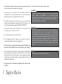
1. Safety Rules
To reduce the risk of electric shock, ensure electricity has been turned off
at the circuit breaker or fuse box before beginning.
All wiring must be in accordance with the National Electrical Code
“ANSI/NFPA 70-1999” and local electrical codes. Electrical installation
should be performed by a qualified licensed electrician.
The outlet box and support structure must be securely mounted and
capable of reliably supporting a minimum of 35 lbs (15.9 kg) or less. Use
only cUL-listed outlet boxes marked “FOR FAN SUPPORT.”
The fan must be mounted with a minimum of 7 ft. (2.1m) clearance from
the trailing edge of the blades to the floor.
Avoid placing objects in the path of the blades.
To avoid personal injury or damage to the fan and other items, be
cautious when working around or cleaning the fan.
Do not use water or detergents when cleaning the fan or fan blades. A dry
dust cloth or lightly dampened cloth will be suitable for most cleaning.
After making electrical connections, spliced conductors should be turned
upward and pushed carefully up into the outlet box. The wires should be
spread apart with the grounded conductor and the equipment-grounding
conductor on one side of the outlet box and ungrounded conductor on the
other side of the outlet box.
All set screws must be checked and retightened where necessary before
installation.
Suitable for use with solid-state speed control.1.
2.
3.
4.
5.
6.
7.
8.
9.
10.
WARNING
TO REDUCE THE RISK OF PERSONALL INJURY, DO NOT BEND THE
BLADE ARMS (ALSO REFERRED TO AS FLANGES), WHEN
INSTALLING THE BRACKETS, BALANCING THE BLADES OR
CLEANING THE FAN. DO NOT INSERT FOREIGN OBJECTS IN –
BETWEEN ROTATING FAN BLADES.
NOTE
READ AND SAVE THESE INSTRUCTIONS
WARNING
TO REDUCE THE RISK OF FIRE, ELECTRIC SHOCK, OR OTHER PERSONAL
INJURY, MOUNT FAN ONLY ON AN OUTLET BOX OR SUPPORTING
SYSTEM MARKED ACCEPTABLE FOR FAN SUPPORT OF 35 LBS (15.9 KG)
OR LESS AND USE MOUNTING SCREWS PROVIDED WITH THE OUTLET
BOX. MOST OUTLET BOXES COMMONLY USED FOR THE SUPPORT OF
LIGHTING FIXTURES ARE NOT ACCEPTABLE FOR FAN SUPPORT AND
MAY NEED TO BE REPLACED. CONSULT A QUALIFIED ELECTRICIAN IF IN
DOUBT.

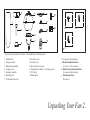
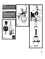
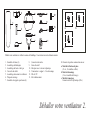
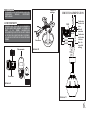
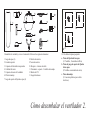
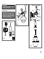
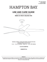
Unpack your fan and check the contents. You should have the following items:
Unpacking Your Fan 2.
14. Loose parts bag containing:
a. Blade attachment hardware
(13 screws, 13 fiber washers)
b. Blade arms attachment hardware
(9 screws with lock washers)
c. Mounting hardware
Wire nuts (3)
1. Fan blades (4)
2. Canopy assembly
3. Ball/downrod assembly
4. Coupling cover
5. Fan motor assembly
6.
Mounting plate
7. Set of blade brackets (4)
8. Decorative cover
9. Decorative nut
10. Receiver with 6 wire nuts
11. Transmitter incl. holder + 2 mounting screws
12. 12V battery
13. Balancing kit
3
4
1
28
11
9
10
5
7
6
14
ab
12
13
c

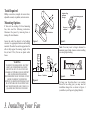
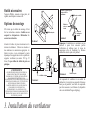
Tools Required
Phillips screw driver, straight slot screw driver,
adjustable wrench, step ladder, and wire cutters.
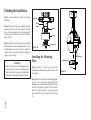
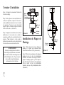
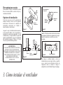
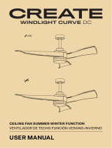
Mounting Options
If there isn't an existing cUL listed mounting
box, then read the following instructions.
Disconnect the power by removing fuses or
turning off circuit breakers.
Secure the outlet box directly to the building
structure. Use appropriate fasteners and building
materials. The outlet box and its support must be
able to fully support the moving weight of the
fan (at least 35 lbs). Do not use plastic outlet
boxes.
Figure 4
Figure 3
Figure 1
Figure 2
Outlet box
Outlet box Outlet box
Note: You may need a longer downrod to
maintain proper blade clearance when installing
on a steep, sloped ceiling.
To hang your fan where there is an existing
fixture but no ceiling joist, you may need an
installation hanger bar as shown in Figure 4
(available at your Progress Lighting Retailer).
3. Installing Your Fan
WARNING
TO REDUCE THE RISK OF FIRE, ELECTRIC
SHOCK, OR OTHER PERSONAL INJURY,
MOUNT FAN ONLY TO AN OUTLET BOX
MARKED ACCEPTABLE FOR FAN SUPPORT
AND USE THE MOUNTING SCREWS
PROVIDED WITH THE OUTLET BOX. OUTLET
BOXES COMMONLY USED FOR THE
SUPPORT OF LIGHTING FIXTURES MAY NOT
BE ACCEPTABLE FOR FAN SUPPORT AND
MAY NEED TO BE REPLACED. CONSULT A
QUALIFIED ELECTRICIAN IF IN DOUBT.
Angled ceiling
maximum
24 angle
Recessed
outlet box
Provide strong support
Ceiling
hanger
bracket

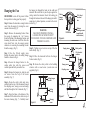
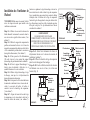
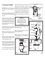
4.
Hanging the Fan
REMEMBER to turn off the power. Follow
the steps below to hang your fan properly:
Step 1. Remove the decorative canopy bottom
cover from the canopy by turning the cover
counter clockwise.(Fig. 5)
Step 2. Remove the mounting bracket from
the canopy by removing the 1 of 2 screws
from the bottom of the mounting bracket and
loosening the other one a half turn from the
screw head. Next, turn the canopy counter
clockwise to removing the mounting bracket
from the canopy. (Fig. 5)
Step 3. Pass the 120-volt supply wires
through the center hole in the ceiling hanger
bracket as shown in Fig. 6.
Step 4. Secure the hanger bracket to the
ceiling outlet box with the screws and
washers provided with your outlet box.
Step 5. Remove the hanger pin, lock pin and
set screws from the top of the motor
assembly. (Fig. 7)
Step 6. Route the safety cable and wires
exiting from the top of the fan motor through
the coupling cover, canopy cover and canopy
and then through the ball / downrod. (Fig. 7)
Step 7. Align the holes at the bottom of the
downrod with the holes in the collar on top of
the motor housing (Fig. 7). Carefully insert
the hanger pin through the holes in the collar and
downrod. Be careful not to jam the pin against the
wiring inside the downrod. Insert the locking pin
through the hole near the end of the hanger pin until it
snaps into its locked position, as noted in the circle
inset of Fig. 7.
WARNING
FAILURE TO PROPERLY INSTALL
LOCKING PIN AS NOTED IN STEP 7
COULD RESULT IN FAN LOOSENING AND
POSSIBLY FALLING.
Figure 6
Figure 7
Ceiling
hanger
bracket
Mounting screws
(supplied with
electrical box)
CUL Listed
electrical
box
120V Wires
Washers
Supply wires
Downrod
Hanger pin Lock pin
Set screws
Canopy
Canopy cover
Coupling cover
Pin in locked
position
Step 8. Tighten two set screws on top of the fan
motor firmly. (Fig. 7)
Step 9. Place the downrod ball into the hanger
bracket socket. (Fig. 8)
Step 10. Secure the safety cable to the building
structure with a wood screw. (wood screw not
supplied) (Fig. 8)
Figure 5
Ceiling hanger
bracket
Ceiling
canopy
Canopy
cover
Safety cable

5.
Figure 8
Hanger
bracket
Canopy
Safety cable
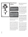
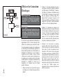
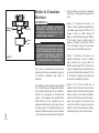
Making the Electrical
Connections
If you feel you do not have enough electrical
wiring knowledge or experience, have your fan
installed by a licensed electrician.
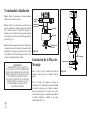
This remote control unit is equipped with 16 code
combinations to prevent possible interference
from or to other remote units. The frequency
switches on your receiver and remote control have
been preset at the factory. Please recheck to make
sure the switches on the remote control and the
receiver are set to the same position. Any
combination of settings will operate the fan as long
as the switches in the remote control and receiver
are set to the same position. (Figure 9)
1.
2.
3.
4.
(Figure 10) Insert the receiver into the
mounting bracket with the flat side of the
receiver facing the ceiling.
(Figure 11) Motor to receiver electrical
connections: Connect the black wire from the
fan to black wire marked "TO MOTOR L".
Connect the white wire from the fan to the
white wire marked "TO MOTOR N" from the
receiver. Connect the blue wire from the fan to
the blue wire marked "For Light" from the
receiver. Secure the wire connections with the
plastic wire connecting nuts provided.
(Figure 11) Receiver to house supply wires
electrical connections: Connect the black (hot)
wire from the ceiling to the black wire marked
"AC in L" from the receiver. Connect the white
(neutral) wire from the ceiling to the white wire
marked "AC in N" from the receiver. Secure
the wire connections with the plastic wire
connecting nuts provided.
(Figure 11) If your outlet box has a ground
wire (green or bare copper) connect it to the fan
ground wires; otherwise connect the hanging
bracket ground wire to the mounting bracket.
Secure the wire connection with a plastic nut
provided. After connecting the wires spread
them apart so that the green and white wires are
on one side of the outlet box and black and blue
wires are on the other side. Carefully tuck the
wire connections up into the outlet box.
TO AVOID POSSIBLE ELECTRICAL SHOCK, BE
SURE ELECTRICITY IS TURNED OFF AT THE
MAIN FUSE BOX BEFORE WIRING.
NOTE
NOTE
FAN MUST BE INSTALLED AT A MAXIMUM
DISTANCE OF 20 FEET FROM THE
TRANSMITTING UNIT FOR PROPER
SIGNAL TRANSMISSION BETWEEN THE
TRANSMITTING UNIT AND THE FAN'S
RECEIVING UNIT.

6.
CAUTION
DO NOT USE WITH A WALL LIGHT DIMMER
SWITCH.
Remote Control
Receiver
SUPPLY CIRCUIT
WHITE
WHITE
BLACK
BLACK
BLUE
Ground
Conductor
Outlet Box
Green
Ground
Lead
GREEN
Ground to
Downrod
BLACK BLACK
BLUE
WHITE
WHITE
WARNING
CHECK TO SEE THAT ALL CONNECTIONS ARE
TIGHT, INCLUDING GROUND, AND THAT NO
BARE WIRE IS VISIBLE AT THE WIRE NUTS.
EXCEPT FOR THE GROUND WIRE.
Receiver
Hanger
bracket
Figure 9
Figure 10
Figure 11

Finishing the Installation
Step 1. Tuck connections neatly into ceiling
outlet box.
Step 2. Slide the canopy up to mounting bracket
and place the key hole on the canopy over the
screw on the mounting bracket, turn canopy until
it locks in place at the narrow section of the key
holes. (Fig. 12)
Step 3. Align the circular hole on canopy with the
remaining hole on the mounting bracket, secure
by tightening the two set screws. Note: Adjust the
canopy screws as necessary until the canopy and
canopy cover are snug.
Installing the Mounting
Plate
Step 1.
Remove 1 of the 3 screws from the
mounting ring and loosen the other 2 screws. (Do
not remove)
Step 2.
Place the key holes on the mounting plate
over the 2 screws previously loosened from the
mounting ring, turn mounting plate until it locks
in place at the narrow section of the key holes.
Secure by tightening the 2 screws previously
loosened and the one previously removed. (Fig.
13)
WARNING
Make sure the notch on the hanging bracket
properly sits in the groove in the hanger ball
before attaching the canopy to the bracket by
turning the housing until it drops into place.
Figure 12
Figure 13
Outlet box
Hanger
bracket
Canopy
Canopy cover
Screws
Mounting plate
Mounting ring
Screws
7.

8.
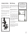
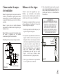
Blade Balancing
All blades are grouped by weight. Because
natural woods very in density, the fan may
wobble even though the blades are weighed
equally.
The following procedure should correct most fan
wobbling problems. Check after each step.
1. Check that all blade and blade arm screws are
secure.
2. Most fan wobbling problems are caused when
blade levels are unequal. Check this level by
selecting a point on the ceiling above the tip of
one of the blades. Measure this distance as
shown in Figure 15. Rotate the fan until the
next blade is positioned for measurement.
Repeat for each blade. The distance deviation
should be equal within 1/8".
3. Use the enclosed Blade Balancing Kit if the
blade wobble is still noticeable.
4. If the blade wobble is still noticeable,
interchanging two adjacent (side by side)
blades can redistribute the weight and possibly
result in smoother operation.
Touching
ceiling
Figure 15
WARNING
TO REDUCE THE RISK OF PERSONAL
INJURY, DO NOT BEND THE BLADE
HOLDERS WHILE INSTALLING, BALANCING
THE BLADES, OR CLEANING THE FAN. DO
NOT INSERT FOREIGN OBJECTS BETWEEN
ROTATING FAN BLADES.
Attaching the Fan Blades
Step 1. Attach the blades to the blade arms using
three screws and fiber washers as shown in Figure
14. Start a screw into the blade arm, do not
tighten. Repeat for the 2 remaining screws and
washers.
Step 2. Tighten each screw securely starting with
the center screw. Make sure the blade is straight.
Step 3. Fasten the blade assembly to the motor
using the motor screws provided.
Step 4. Repeat these steps for the remaining
blades.
Figure 14
Screws
Screws
Blades
Blade arms
Fiber
washers

9.
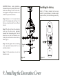
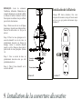
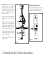
Installing the
Decorative Cover
CAUTION: Before starting installation,
disconnect the power by turning off the circuit
breaker or removing the fuse at fuse box.
Turning power off using the fan switch is not
sufficient to prevent electric shock.
Step 1. Remove the 1 of 3 screws from the
posts of the mounting plate and keep it for
future use. Loosen the other 2 screws. (Do not
remove)
Step 2. Place the key holes in the decorative
cover over the two screws previously
loosened from the mounting plate. Turn the
decorative cover until the decorative cover
locks in place at the narrow section of the key
holes. (Fig. 16)
Step 3. Securely tighten the two mounting
screws previously loosened and the one
previously removed.
Step 4.
Fit the decorative nut onto the
decorative cover.
Figure 16
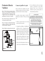
Installing the battery
Install a 12V battery (included) into the remote
control. To prevent damage to the remote control,
remove the battery if not used for long periods. (Fig.
17)
Figure 17
Screws
Mounting
plate
Decorative
nut
Decorative
cover

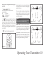
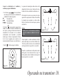
Operating Your Transmitter
10.
Restore power to ceiling fan and test for proper
operation.
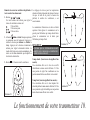
1. " , , " buttons:
These three buttons are used to set the fan
speed as follows:
= Low speed
= Medium speed
= High speed
2. The " " button turns the light ON or OFF and
also controls the brightness setting. Press and
release the button to turn the light ON or OFF.
Press and hold the button to set the desired
brightness. The light key has an auto-resume, it
will stay at the same brightness as the last time it
was turned off.
3. " " button: This button turns the fan off.
Speed settings for warm or cool weather depend
on factors such as the room size, ceiling height,
number of fans, etc.
The reverse switch is located on the top of motor
housing. Slide the switch to the left for warm
weather operation. Slide the switch to the right for
cool weather operation.
Warm weather - (Counter-Clockwise direction)
A downward air flow creates a cooling effect.(Fig.
19) This allows you to set your air conditioner on
a higher setting without affecting your comfort.
Cool weather - (Clockwise direction) An upward
airflow moves warm air off the ceiling area. (Fig.
20) This allows you to set your heating unit on a
lower setting without affecting your comfort.
NOTE
WAIT FOR FAN TO STOP BEFORE CHANGING
THE SETTING OF THE SLIDE SWITCH.
Figure 18
Figure 19
Figure 20

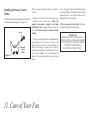
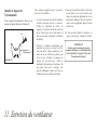
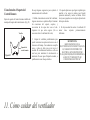
11. Care of Your Fan
Here are some suggestions to help you maintain
your fan
1. Because of the fan's natural movement, some
connections may become loose.
Check the
support connections, brackets, and blade
attachments twice a year.
Make sure they are
secure.
(It is not necessary to remove fan from
ceiling.)
2. Clean your fan periodically to help maintain its
new appearance over the years. Use only a soft
brush or lint-free cloth to avoid scratching the
finish. The plating is sealed with a lacquer to
minimize discoloration or tarnishing. Do not use
water when cleaning. This could damage the
motor, or the wood, or possibly cause an electrical
shock.
3. You can apply a light coat of furniture polish
to the wood blades for additional protection and
enhanced beauty. Cover small scratches with a
light application of shoe polish.
4.
There is no need to oil your fan.
The motor
has permanently lubricated bearings.
IMPORTANT
MAKE SURE THE POWER IS OFF AT
THE ELECTRICAL PANEL BOX BEFORE
YOU ATTEMPT ANY REPAIRS. REFER
TO THE SECTION "MAKING
ELECTRICAL CONNECTIONS".
Attach the remote control holder with the remote
control holder mounting screw. (Figure 21)
Remote
Control
Holder
Screw
Installing the Remote Control
Holder
Figure 21

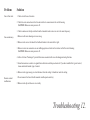
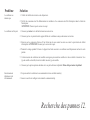
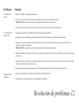
Troubleshooting
12.
Solution
1. Check circuit fuses or breakers.
2. Check line wire connections to the fan and switch wire connections in the switch housing.
CAUTION: Make sure main power is off.
3. Check to make sure the dip switches from the transmitter and receiver are set to the same frequency.
1. Make sure all motor housing screws are snug.
2. Make sure the screws that attach the fan blade bracket to the motor hub is tight.
3. Make sure wire nut connections are not rubbing against each other or the interior wall of the switch housing.
CAUTION: Make sure main power is off.
4. Allow a 24-hour "breaking-in" period. Most noise associated with a new fan disappear during this time.
5. Some fan motors are sensitive to signals from solid-state variable speed controls. If you have installed this type of control,
choose and install another type of control.
6. Make sure the upper canopy is a short distance from the ceiling. It should not touch the ceiling.
1. Do not connect the fan with wall mounted variable speed control (s).
2. Make sure the dip switches are set correctly.
Problem
Fan will not start.
Fan sounds noisy.
Remote control
malfunction

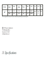
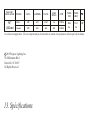
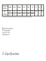
13.
Specifications
2019 Progress Lighting, Inc.
701 Millennium Blvd.,
Greenville, SC 29607
All Rights Reserved
c
20.06
lbs
22.11
lbs
1.89'
Fan Size
Speed Volts
Amps Watts RPM CFM N.W. G.W. C.F.
56"
Low
High
120
120
These are approximate measures. They do not include Amps and Wattage used by the light kit.
0.23
0.56
12.02
66.8
56
148
2250.56
6255.84

Manuel d'installation du ventilateur de plafond
P250010
93114642_A

Garantie à vie limitée
Progress Lighting garantit à l’acheteur initial que les moteurs de ventilateur sont exempts de défauts électriques ou mécaniques
tant que l’acheteur initial est propriétaire du ventilateur. Les interrupteurs à chaînette, les interrupteurs inverseurs, les
condensateurs et les finis métalliques sont garantis contre les défauts de matériaux ou de fabrication pendant une période d’un
an à partir de la date d’achat. Le gauchissement des pales de bois ou de plastique n’est pas couvert par la présente garantie, ni la
corrosion ou la détérioration du fini des ventilateurs installés à moins de dix milles d’un bord de mer. Les garanties prolongées
pour les produits homologués ENERGY STAR® peuvent s’appliquer.
Lorsqu’ils sont installés correctement et dans des conditions d’utilisation normales, les ventilateurs de plafond Progress
Lighting dotés d’une source lumineuse à DEL intégrée sont garantis contre les défauts de matériaux et de fabrication causant le
non fonctionnement de la source lumineuse selon les spécifications pendant (i) cinq (5) ans à partir de la date d’achat des
modules d’éclairage à DEL et des composants électriques des ventilateurs pour les résidences unifamiliales et (ii) trois (3) ans à
partir de la date d’achat des modules d’éclairage à DEL et des composants électriques des ventilateurs pour les résidences
multifamiliales et pour les utilisations commerciales. Les ampoules à DEL fournies par Progress Lighting ne sont assorties
d’aucune autre garantie que celle du fabricant. Les ampoules autres qu’à DEL ne sont assorties d’aucune garantie.
En fournissant la preuve d’achat, l’acheteur initial peut retourner le ventilateur défectueux à son lieu d’achat pendant les 30
premiers jours afin qu’il soit remplacé. Après 30 jours, l’acheteur initial DOIT communiquer avec Progress Lighting au 864
678-1000 pour la réparation ou le remplacement du ventilateur, ce qui sera déterminé exclusivement par Progress Lighting et
constituera le seul et unique recours de l’acheteur.
Main-d’oeuvre et expédition exclus. La présente garantie ne couvre par les coûts et les frais associés à la main-d’oeuvre (y
compris, sans s’y limiter, les frais d’électricien) nécessaires à l’installation, au retrait ou au remplacement du ventilateur ou des
pièces du ventilateur.
La présente garantie ne s’applique pas en cas de perte ou de dommage découlant (i) de l’usure normale, de l’altération ou d’un
usage incorrect, abusif ou négligent ou (ii) d’une installation, d’une utilisation, d’une réparation ou d’un entretien inadéquats par
l’acheteur initial ou un tiers, y compris, sans s’y limiter, une tension électrique inadéquate ou une surtension, l’utilisation de
pièces ou d’accessoires inadéquats, une réparation non autorisée (effectuée ou tentée) ou l’omission d’entretenir le ventilateur.
LES GARANTIES QUI PRÉCÈDENT ÉNONCENT L’ENTIÈRE RESPONSABILITÉ DE PROGRESS LIGHTING AU
CHAPITRE DE LA GARANTIE AINSI QUE LE SEUL ET UNIQUE RECOURS DE L’ACHETEUR LIÉ À CES PRODUITS.
PROGRESS LIGHTING N’EST PAS RESPONSABLE DES DOMMAGES (Y COMPRIS LES DOMMAGES INDIRECTS,
SPÉCIAUX, ACCESSOIRES OU CONSÉCUTIFS) ATTRIBUABLES À LA DÉFECTUOSITÉ DU PRODUIT, QU’ILS
SOIENT LIÉS À UNE VIOLATION DE LA GARANTIE, UNE VIOLATION DU CONTRAT OU AUTRE. LA PRÉSENTE
GARANTIE REMPLACE TOUTE AUTRE GARANTIE, EXPRESSE OU IMPLICITE, Y COMPRIS TOUTE GARANTIE
DE QUALITÉ MARCHANDE, D’UTILITÉ À UNE FIN PARTICULIÈRE OU D’ABSENCE DE CONTREFAÇON.
Certains États ne permettent pas de limitation à la durée implicite d’une garantie ou d’exclusion ou de limitation des dommages
accessoires ou consécutifs. Par conséquent, les limitations ci-dessus pourraient ne pas s’appliquer
Date de l’achat
Magasin
Nº de modèle
Nº de série
Nº du fournisseur
CUP
109226
785247240876
785247240869

Règles de sécurité
........................................................................................................................................................................
Déballer votre ventilateur
...........................................................................................................................................................
Installation du ventilateur
...........................................................................................................................................................
Installation de la couverture décorative
....................................................................................................................................
Le fonctionnement de votre transmetteur
...............................................................................................................................
Entretien du ventilateur
.............................................................................................................................................................
Recherche des pannes
................................................................................................................................................................
Spécifications
..............................................................................................................................................................................
1.
2.
3.
9.
10.
11.
12.
13.
Table des matières

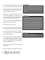
Pour rèduire les risques de décharge électrique, s'assurer que l'électricité
est coupée au disjoncteur ou au boîtier de fusibles avant de commencer.
Tous les càblages doivent se conformer au Code National de électricite ét
aux normes électriques locales. L'installation électrique doit être
effectuée par un électricien licencié qualifie.
Le boîtier de prise et son support doivent être attachés correctement et
capables de supporter fiablement un poids minimum de 15.8 kg (35
livres). Utiliser seulement les boîtiers de prise homologués par l'cUL et
portant l'étiquette "POUR LE SUPPORT DE VENTILATEUR".
Le ventilateur doit être monté à une hauteur minimum de 2.1m (7
pieds) entre le bord de fuite des ailettes et le sol.
Éviter de placer des objets en travers des ailettes.
Pour éviter les blessures ou les dommages du ventilateur et autres
articles, faire attention en travaillant sur le ventilateur ou en le nettoyant.
Ne pas utilliser d'eau ou de détergent pout nettoyer le ventilateur ou ses
ailettes. Un chiffon de poussiére sec ou un chiffon lègérement humide
suffit pour la plupart des nettoyages.
Aprés le branchement électrique, las épissures de conducteurs doivent
être orientées vers le haut et poussées soigneusement dans le boîtier de
prise. Les fils doivent être éloignés les uns des autres, et le conducteur
mis à la terre et le conducteur de mise à la terre de l'appareil doivent être
placés sur un coté du boîtier de prise.
Toutes les vis de réglage doivent être vérifiées et resserrées si nécessaire
avant l'installation.
Adapté pour une utilisation avec la commande de vitesse à l'état solide.
1.
2.
3.
4.
5.
6.
7.
8.
9.
10.
1. Règles de sécurité
REMARQUE
LIRE ET CONSERVER CES INSTRUCTIONS
AVERTISSEMENT
POUR RÉDUIRE LES RISQUES DE BLESSURE, NE PLIEZ PAS LES SUPPORTS
DE PALE (AUSSI APPELÉS BRIDES) PENDANT L'INSTALLATION DES
CROCHETS, L'ÉQUILIBRAGE DES PALES OU LE NETTOYAGE DU
VENTILATEUR.
AVERTISSEMENT
AFIN DE RÉDUIRE LE RISQUE D’INCENDIE, DE DÉCHARGE ÉLECTRIQUE,
DE BLESSURE CORPORELLE, INSTALLER À UNE BOÎTE DE SORTIE
CAPABLE DE « SOUTENIR UN VENTILATEUR DE 15,8 KG (35 LB) OU
MOINS » ET UTILISER LES VIS D’INSTALLATION COMPRISES AVEC LA
BOÎTE DE SORTIE. LA PLUPART DES BOÎTES DE SORTIE UTILISÉES POUR
SOUTENIR LES LUMINAIRES SONT INADAPTÉES AU SOUTIEN D’UN
VENTILATEUR ET POURRAIENT EXIGER UN REMPLACEMENT. À CAUSE
DE L’INSTALLATION COMPLEXE DE CE VENTILATEUR, NOUS
RECOMMANDONS LES SERVICES D’UN MAÎTRE ÉLECTRICIEN.
La page est en cours de chargement...
La page est en cours de chargement...
La page est en cours de chargement...
La page est en cours de chargement...
La page est en cours de chargement...
La page est en cours de chargement...
La page est en cours de chargement...
La page est en cours de chargement...
La page est en cours de chargement...
La page est en cours de chargement...
La page est en cours de chargement...
La page est en cours de chargement...
La page est en cours de chargement...
La page est en cours de chargement...
La page est en cours de chargement...
La page est en cours de chargement...
La page est en cours de chargement...
La page est en cours de chargement...
La page est en cours de chargement...
La page est en cours de chargement...
La page est en cours de chargement...
La page est en cours de chargement...
La page est en cours de chargement...
La page est en cours de chargement...
La page est en cours de chargement...
La page est en cours de chargement...
La page est en cours de chargement...
La page est en cours de chargement...
-
 1
1
-
 2
2
-
 3
3
-
 4
4
-
 5
5
-
 6
6
-
 7
7
-
 8
8
-
 9
9
-
 10
10
-
 11
11
-
 12
12
-
 13
13
-
 14
14
-
 15
15
-
 16
16
-
 17
17
-
 18
18
-
 19
19
-
 20
20
-
 21
21
-
 22
22
-
 23
23
-
 24
24
-
 25
25
-
 26
26
-
 27
27
-
 28
28
-
 29
29
-
 30
30
-
 31
31
-
 32
32
-
 33
33
-
 34
34
-
 35
35
-
 36
36
-
 37
37
-
 38
38
-
 39
39
-
 40
40
-
 41
41
-
 42
42
-
 43
43
-
 44
44
-
 45
45
-
 46
46
-
 47
47
-
 48
48


Progress Lighting P250010 Guide d'installation
- Catégorie
- Ventilateurs ménagers
- Taper
- Guide d'installation
dans d''autres langues
Documents connexes
-
Progress Lighting P250000-081 Guide d'installation
-
Progress Lighting 93114656 B Mode d'emploi
-
-
-
-
-
-
-
 PROGRESS LIGHTNING P250002-143-30 Mode d'emploi
-

Autres documents
-
 Kichler Lighting Motu Manuel utilisateur
-
 Hinkley 903752 52 Inch Chisel Ceiling Fan Manuel utilisateur
-
 Hinkley 903760 60 Inch Chisel Ceiling Fan Manuel utilisateur
-
Create Wind Stylance DC Manuel utilisateur
-
 Hampton Bay 58913 Mode d'emploi
-
 Create WINDLIGHT CURVE DC Le manuel du propriétaire
-
Parrot Uncle F8261110V Guide d'installation
-
Hinkley 903880FGT-NDD Manuel utilisateur
-
-


