Robertshaw 6500-347M Series Infinite Switch Kit Manuel utilisateur
- Taper
- Manuel utilisateur

INSTALLATION DATA
6500-347M SERIES INFINITE SWITCH KIT
The Robertshaw
®
6500 M Series is a voltage sensing (parallel circuit)
innite switch designed to replace the current VSI (INF) switch in Canada.
This patented control is the smallest physical dimension possible to meet
common applicaon specicaons.
Specicaons:
UL Approved #E112536
15 Amps @ 120/240 Volt 50/60 Hz for 200°F (93°C) ambient
13 Amp rang for all temperatures up to the maximum ambient
temperature of 257°F (125°C)
Key Features:
Counterclockwise sha rotaon from OFF
Controllable range of output power with LO and HI detents
Compact and lightweight design
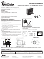
PANEL
ì VENTSUPî
FLATHEAD
SCREWS
Figure 1
INSTALLATION INSTRUCTIONS
CAUTION: This device should be installed by a qualied service technician
with due regard for safety, as improper installaon could result in a
hazardous condion.
1. Unplug range or disconnect power.
2. Remove dial from switch.
3. Gain access to the inoperave switch. Refer to the original user manual
for the appliance for proper disassembly.
4. Label all wires with tags or make an exact drawing of wiring
conguraon before removing any wires.
5. Remove original switch.
Note: The 6500 M must be mounted with the sloed vents at the top.
(Figure 1)
6. Aach the new switch to the rear panel with the original screws or using
the screws supplied in the kit.
7. Place the original dial on the new switch sha. Make sure the sha goes
in all the way.
8. If wires on the appliance have been cut previously the included clips and
screws will allow installaon of the bare wire to the terminal.
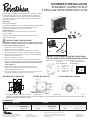
WIRING ROBERTSHAW INF TO ROBERTSHAW
6500 M SERIES
Connect wires from old switch to new switch as follows:
INF Switch 6500 M (MPA)
Terminal # Switch Terminal #
L1 connect to L1
L2 connect to L2
P connect to P
H1 connect to H1
H2 connect to HC
(L2)
(P)
(L1)
(H1)
(HC)
0.75
0.75
1.10
MAX DISTANCE
0.614
1.50
0.8860.886
1.77
(4X) 8-32 MOUNTING NUTS
WIRING SCHEMATIC
WARNING: The rear housing has a ¼” diameter hole which is an access point to be used ONLY by qualied personnel for insuring proper assembly and calibraon of the switch. Any tampering
with internal components or altering factory sengs of this switch will possibly damage other electrical components on the appliance and will immediately VOID the WARRANTY of the switch.
MOUNTING DIMENSIONS
ORDERING INFORMATION
PART NUMBER FACTORY PART NUMBER PART NUMBER FACTORY PART NUMBER VOLTAGE NOTES
6500-347M MPA-V657-ICM 6500-347 INF-240-1158 240V AC Stem Flat Down
6500 M SERIES
REPLACES
Dial Shaft Type P
Customer Service Telephone 1.800.304.6563
Customer Service Facsimile 1.800.426.0804
Robertshaw® and Uni-Line® are trademarks of Robertshaw, its
subsidiaries and/or affiliated companies. All other brands mentioned
may be the trademarks of their respective owners.
For Technical Service
Telephone 1.800.445.8299
www.robertshaw.com
©2018 Robertshaw
02/18 –352-00269-001

DONNÉES D’INSTALLATION
ENSEMBLE COMMUTATEUR
ÀRÉGLAGE INFINI SÉRIE 6500-347M
Le commutateur Robertshaw
®
Série 6500 M est un commutateur à réglage
inni et détecon de tension (circuit parallèle) desné à remplacer le
commutateur VSI (INF) au Canada. Cee commande brevetée présente
la plus pete dimension physique possible conforme aux spécicaons
d’applicaon courantes.
Spécicaons:
Homologué UL #E112536
15 A à 120/240 V, 50/60 Hz pour une température ambiante de 200 °F (93 °C)
Intensité nominale de 13 A pour toutes les températures jusqu’à
la température ambiante maximum de 257 °F (125 °C)
Caractérisques clés:
Rotaon de ge dans le sens horaire ou an-horaire à parr de
la posion ARRÊT
Plage de puissance de sore réglable avec détentes MIN. et MAX.
Concept compact et léger
INSTRUCTIONS D’INSTALLATION
ATTENTION: Ce disposif doit être installé par un agent technique qualié
qui respecte les consignes de sécurité, car une installaon impropre peut
se solder par des condions dangereuses.
1. Débrancher la cuisinière ou couper le courant.
2. Déposer le cadran du commutateur.
3. Accéder au commutateur inopérant. Se référer aux instrucons
de démontage dans le manuel de l’ulisateur d’origine de l’appareil.
4. Équeter tous les ls ou dessiner un croquis exact de la conguraon
des ls avant de les débrancher.
5. Déposer le commutateur d’origine.
6. Aacher le nouveau commutateur au panneau arrière avec les vis
d’origine ou à l’aide des deux vis à tête plate fournies dans l’ensemble.
Remarque: Le 6500 M doit être monté avec les fentes d’aéraon sur
le dessus (Figure 1.)
7. Monter temporairement le commutateur et placer le cadran
d’origine sur la nouvelle ge du commutateur. S’assurer que
la ge est complètement enfoncée.
8. Si les ls de l’appareil ont été coupés auparavant, les clips et vis inclus
permeront l’installaon du l dénudé sur le terminal.
PANNEAU
FENTES VERS LE HAUT
VIS À TÊTE
PLATE
Figure 1
Figure 1
CÂBLAGE D’UN COMMUTATEUR INF ROBERTSHAW
SUR UN COMMUTATEUR ROBERTSHAW SÉRIE 6500 M
Brancher comme suit les ls de l’ancien commutateur sur le nouveau:
N
o
de borne N
o
de borne du commutateur
du commutateur INF 6500 M (MPA)
L1 brancher sur L1
L2 brancher sur L2
P brancher sur P
H1 brancher sur H1
H2 brancher sur HC
(L2)
(P)
(L1)
(H1)
(HC)
0.75
0.75
1.10
DISTANCE MAX.
0.614
1.50
0.8860.886
1.77
4 ÉCROUS DE MONTAGE 8-32
SCHÉMA DE CÂBLAGE
AVERTISSEMENT: Le boîer arrière a un trou de ¼ po (6 mm) de diamètre qui est un point d’accès RÉSERVÉ à un personnel qualié pour garanr l’assemblage et l’étalonnage corrects du
commutateur. Toute altéraon des composants internes ou modicaon des réglages en usine de ce commutateur risque d’endommager d’autres composants électriques sur l’appareil et
ANNULERA immédiatement la GARANTIE du commutateur.
DIMENSIONS DE MONTAGE
COMMANDES
NUMÉRO DE PIÉCE NUMÉRO
DE PIÉCE D’USINE
NUMÉRO DE PIÉCE NUMÉRO
DE PIÉCE D’USINE
TENSION NOTES
6500-347M MPA-V657-ICM 6500-347 INF-240-1158 240V AC Tige plate vers le bas
SÉRIE 6500 M
REMPLACE
POUR LES VEILLEUSES 240 V;
-- CONNECTER LES CONDUCTEURS
DE VEILLEUSE SUR « P » ET « L2 »
Veilleuse 120 V
120 V
120 V
240 V
À MONTER DE L’UN OU L’AUTRE
CÔTÉ DE CES DEUX (2) CÔTÉS
À FENTES DE VENTILATION
VERS LE HAUT
TYPE D’ARBRE DE CADRAN P
Service à la clientèle Téléphone 1.800.304.6563
Service à la clientèle Télécopieur 1.800.426.0804
Robertshaw® et Uni-Line® sont des marques de commerce
de Robertshaw et/ou de ses filiales. Toutes les autres marques
mentionnées peuvent être les marques de commerce de leur
propriétaire respectif.
Service technique
Téléphone 1.800.445.8299
www.robertshaw.com
©2018 Robertshaw
02/18 –352-00269-001
-
 1
1
-
 2
2


Robertshaw 6500-347M Series Infinite Switch Kit Manuel utilisateur
- Taper
- Manuel utilisateur
dans d''autres langues
Documents connexes
-
Robertshaw 6500 M Series Infinite Switch Kit Manuel utilisateur
-
Robertshaw SmartSense SMART-R-06 Remote Temperature Sensor Manuel utilisateur
-
-
-
-
-
-
-
-