La page est en cours de chargement...

English
FLEX I/O is a trademark of Rockwell Automation
Publication 1794-5.3 – July 1999
(Cat. No. 1794-OB16)
4
1
3
2
5
6
7
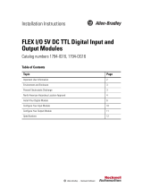
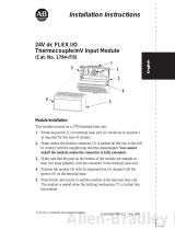
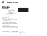
Module Installation
This module mounts on a 1794 terminal base unit.
1. Rotate keyswitch (1) on terminal base unit (2) clockwise to position 2
as required for this type of module.
2. Make certain the flexbus connector (3) is pushed all the way to the left
to connect with the neighboring terminal base/adapter. You cannot
install the module unless the connector is fully extended.
3. Make sure that the pins on the bottom of the module are straight so
they will align properly with the connector in the terminal base unit.
4. Position the module (4) with its alignment bar (5) aligned with the
groove (6) on the terminal base.
5. Press firmly and evenly to seat the module in the terminal base unit.
The module is seated when the latching mechanism (7) is locked into
the module.
!
ATTENTION: To use this module in a complementary
I/O system, refer to your Remote I/O Adapter module
documentation.
Installation Instructions

24V dc
FLEX I/O 16 Source Output Module2
Publication 1794-5.3 – July 1999
!
ATTENTION: Remove field-side power before
removing or inserting this module. This module is
designed so you can remove and insert it under
backplane power. When you remove or insert a module
with field-side power applied, an electrical arc may
occur. An electrical arc can cause personal injury or
property damage by:
• sending an erroneous signal to your system’s field
devices causing unintended machine motion
• causing an explosion in a hazardous environment
Repeated electrical arcing causes excessive wear to
contacts on both the module and its mating connector.
Worn contacts may create electrical resistance.
European Union Directive Compliance
If this product has the CE mark it is approved for installation within the
European Union and EEA regions. It has been designed and tested to meet
the following directives.
EMC Directive
This product is tested to meet Council Directive 89/336/EEC
Electromagnetic Compatibility (EMC) and the following standards, in
whole or in part, documented in a technical construction file:
• EN 50081-2 EMC – Generic Emission Standard, Part 2 – Industrial
Environment
• EN 50082-2 EMC – Generic Immunity Standard, Part 2 – Industrial
Environment
This product is intended for use in an industrial environment.
Low Voltage Directive
This product is tested to meet Council Directive 73/23/EEC Low Voltage,
by applying the safety requirements of EN 61131–2 Programmable
Controllers, Part 2 – Equipment Requirements and Tests.
For specific information required by EN 61131-2, see the appropriate
sections in this publication, as well as the following Allen-Bradley
publications:
• Industrial Automation Wiring and Grounding Guidelines For Noise
Immunity, publication 1770-4.1
• Automation Systems Catalog, publication B111
This equipment is classified as open equipment and must be mounted in
an enclosure during operation to provide safety protection.

24V dc
FLEX I/O 16 Source Output Module 3
Publication 1794-5.3 – July 1999
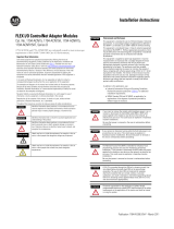
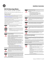
Wiring to a 1794-TB2, -TB3 or -TB3S Terminal Base Unit
1. Connect individual outputwiring to numbered terminals on the 0–15
row (A) as indicated in the table below.
1. Connect the associated output common to the corresponding terminal
on the 16–33 row (B) for each output as indicated in the table below.
(Commons are internally connected together.)
2. Connect +24V dc power to terminal 34 on the 34–51 row (C).
3. Connect dc return to terminal 16 on the 16–33 row (B).
4. If continuing power to the next terminal base unit, connect a jumper
from terminal 51 (+24V dc) on this base unit to terminal 34 on the
next base unit.
5. If continuing common to the next terminal base unit, connect a jumper
from terminal 33 (common) on this base unit to terminal 16 on the
next base unit.
17 18 19 20 21 22 23 24 25 26 27 28 29 30 31 32 33
0 1 2 3 4 5 6 7 8 9 10 11 12 13 14 15
16
1
2
345
6
7
8
91
0
11 1
2
13 14 15
0
35 36 37 38 39 40 41 42 43 44 45 46 47 48 49 50 51
34
1794-TB3
0 –15
34–51
16–33
A
B
C
0123456789101112131415
18 19 20 21 22 23 3324 25 26 27 28 29 30 31 3217
35 36 37 38 47 48 49 5034
51
16
Label placed at top of wiring area.
Row A
Row B
Row C
Row A
Row B
Row C
39 40 41 42 43 44 45 46
1794-TB3S
ATTENTION: Total current draw through the terminal
base unit is limited to 10A. Separate power connections to
the terminal base unit may be necessary.

24V dc
FLEX I/O 16 Source Output Module4
Publication 1794-5.3 – July 1999
Output
Output
Terminal
Common
Terminal
Output
Output
Terminal
Common
Terminal
Output 0 A–0 B–17 Output 8 A–8 B–25
Output 1 A–1 B–18 Output 9 A–9 B–26
Output 2 A–2 B–19 Output 10 A–10 B–27
Output 3 A–3 B–20 Output 11 A–11 B–28
Output 4 A–4 B–21 Output 12 A–12 B–29
Output 5 A–5 B–22 Output 13 A–13 B–30
Output 6 A–6 B–23 Output 14 A–14 B–31
Output 7 A–7 B–24 Output 15 A–15 B–32
Common B–16 thru B–33 +24v dc C–34 thru C–51
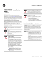
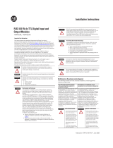
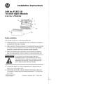
Indicators
1514131211109876543210
24 VDC SOURCE OUTPUT
1794–OB16
2
Allen-Bradley
BA
A = Status Indicators – show status of individual outputs.
B = Insertable label for writing individual output designations.
Memory Mapping
Bit⇒
Word⇓
15 14 13 12 11 10 09 08 07 06 05 04 03 02 01 00
Read Not used
Write O15 O14 O13 O12 O11 O10 O9 O8 O7 O6 O5 O4 O3 O2 O1 O0
Where: O = Output value

24V dc
FLEX I/O 16 Source Output Module 5
Publication 1794-5.3 – July 1999
Specifications – 24V dc Output Module Cat. No. 1794-OB16
Number of Outputs 16 (1 group of 16), non-isolated, sourcing
Module Location Cat. No. 1794-TB3, -TB3S Terminal Base Unit
ON-state Voltage Range 10V dc minimum
24V dc nominal;
31.2V dc maximum
Output Current Rating 8A (16 outputs @ 0.5A)
OFF-state Voltage 31.2V dc maximum
ON-state Current 1.0mA minimum per channel
500mA maximum per channel
Surge Current 2A for 50ms, repeatable every 2 seconds
OFF-state Leakage 0.5mA maximum
ON-state Voltage Drop 0.5V dc maximum
Isolation Voltage (minimum) 100% tested at 850V dc for 1s between user
and system
No isolation between individual channels
Output Signal Delay
Off to On
On to Off
0.5ms maximum
1.0ms maximum
Flexbus Current (maximum) 80mA
Power Dissipation 5.3W maximum @ 31.2V
Thermal Dissipation 18.1 BTU/hr @ 31.2V dc
Indicators (field side
indication, logic driven)
16 yellow status indicators
Fuse recommendations
1
Fusing of outputs is recommended.
Use SAN–O MQ4–800mA fuses
Keyswitch Position 2
Specifications continued on next page.

24V dc
FLEX I/O 16 Source Output Module6
Publication 1794-5.3 – July 1999
Specifications – 24V dc Output Module Cat. No. 1794-OB16
General Specifications
External dc Power
Supply Voltage
Voltage Range
Supply Current
24V dc nominal
19.2 to 31.2V dc (includes 5% ac ripple)
49mA @ 24V dc (38 to 65mA)
Dimensions Inches
(Millimeters)
1.8H x 3.7W x 2.1D
(45.7 x 94.0 x 53.3)
Environmental Conditions
Operational Temperature
Storage Temperature
Relative Humidity
Shock Operating
Non-operating
Vibration
0 to 55
o
C (32 to 131
o
F)
–40 to 85
o
C (–40 to 185
o
F)
5 to 95% noncondensing
30 g peak acceleration, 11(+
1)ms pulse width
50 g peak acceleration, 11(+
1)ms pulse width
Tested 5 g @ 10–500Hz per IEC 68-2-6
Conductors Wire Size
Category
12 gauge (4mm
2
) stranded maximum
3/64 inch (1.2mm) insulation maximum
2
1
Agency Certification
• CSA certified
• CSA Class I, Division 2
Groups A, B, C, D certified
• UL listed
• CE marked for all applicable directives
1
You use this conductor category information for planning conductor routing. Refer to publication
1770-4.1, “Industrial Automation Wiring and Grounding Guidellines for Noise Immunity.”

24V dc
FLEX I/O 16 Source Output Module 7
Publication 1794-5.3 – July 1999
CSA Hazardous Location Approval Approbation d’utilisation dans des
emplacements dangereux par la CSA
CSA
certifies products for general use as well as
for use in hazardous locations. Actual CSA
certification is indicated by the product label
as shown below, and not by statements in any
user documentation.
La CSA
certifie les produits d’utilisation générale
aussi bien que ceux qui s’utilisent dans des
emplacements dangereux. La certification CSA en
vigueur est indiquée par l’étiquette du produit et
non par des affirmations dans la documentation à
l’usage des utilisateurs.
Example of the CSA certification product label
I
Exemple d’étiquette de certfication d’un produit par la CSA
I
To comply with CSA certification for use in
hazardous locations, the following information
becomes a part of the product literature for
CSA-certified Allen-Bradley industrial control
products.
• This equipment is suitable for use in Class I,
Division 2,
Groups A, B, C, D, or non-hazardous locations
only.
• The products having the appropriate CSA
markings (that is, Class I Division 2, Groups A,
B, C, D), are certified for use in other
equipment where the suitability of combination
(that is, application or use) is determined by
the CSA or the local inspection office having
jurisdiction.
Pour satisfaire à la certification de la CSA dans des
endroits dangereux, les informations suivantes font
partie intégrante de la documentation des produits
industriels de contrôle Allen-Bradley certifiés par la
CSA.
• Cet équipement convient à l’utilisation dans des
emplacements de Classe I, Division 2, Groupes A,
B, C, D, ou ne convient qu’à l’utilisation dans des
endroits non dangereux.
• Les produits portant le marquage approprié de la
CSA (c’est à dire, Classe I, Division 2, Groupes A,
B, C, D) sont certifiés à l’utilisation pour d’autres
équipements où la convenance de combinaison
(application ou utilisation) est déterminée par la
CSA ou le bureau local d’inspection qualifié.
Important: Due to the modular nature of a PLC
control system, the product with the highest
temperature rating determines the overall
temperature code rating of a PLC control system
in a Class I, Division 2 location. The temperature
code rating is marked on the product label as
shown.
Important: Par suite de la nature modulaire du
système de contrôle PLC
, le produit ayant le taux le
plus élevé de température détermine le taux
d’ensemble du code de température du système de
contrôle d’un PLC dans un emplacement de Classe I,
Division 2. Le taux du code de température est
indiqué sur l’étiquette du produit.
Temperature code rating
Look for temperature
code rating here
I
Le taux du code de
température est indiqué ici
Taux du code de tempéra-
ture
I
The following warnings apply to products having
CSA certification for use in hazardous locations.
Les avertissements suivants s’appliquent aux produits
ayant la certification CSA pour leur utilisation dans
des emplacements dangereux.

24V dc
FLEX I/O 16 Source Output Module8
Publication 1794-5.3 – July 1999
Approbation d’utilisation dans des
emplacements dangereux par la CSA
CSA Hazardous Location Approval
!
ATTENTION: Explosion hazard —
• Substitution of components may
impair suitability for Class I,
Division 2.
• Do not replace components unless
power has been switched off or the
area is known to be non-hazardous.
• Do not disconnect equipment unless
power has been switched off or the
area is known to be non-hazardous.
• Do not disconnect connectors
unless power has been switched off
or the area is known to be
non-hazardous. Secure any
user-supplied connectors that mate
to external circuits on an
Allen-Bradley product using screws,
sliding latches, threaded connectors,
or other means such that any
connection can withstand a 15
Newton (3.4 lb.) separating force
applied for a minimum of one
minute.
!
AVERTISSEMENT: Risque d’explosion —
• La substitution de composants peut
rendre ce matériel inacceptable pour
lesemplacements de Classe I, Division
2.
• Couper le courant ou s’assurer
quel’emplacement est désigné non
dangereux avant de remplacer
lescomposants.
• Avant de débrancher l’équipement,
couper le courant ou s’assurer que
l’emplacement est désigné non
dangereux.
• Avant de débrancher les connecteurs,
couper le courant ou s’assurer que
l’emplacement est reconnu non
dangereux. Attacher tous connecteurs
fournis par l’utilisateur et reliés aux
circuits externes d’un appareil
Allen-Bradley à l ’aide de vis, loquets
coulissants, connecteurs filetés ou
autres moyens permettant aux
connexions de résister à une force de
séparation de 15 newtons (3,4 lb. - 1,5
kg) appliquée pendant au moins une
minute.
Le sigle CSA est la marque déposée de l’Association des Standards pour le Canada.
PLC est une marque déposée de Allen-Bradley Company, Inc.
CSA logo is a registered trademark of the Canadian Standards Association
PLC is a registered trademark of Allen-Bradley Company, Inc.
With major offices worldwide.
World Headquarters,
Allen-Bradley,
1201 South Second Street,
Milwaukee, WI 53204 USA,
Tel: (1) 414 382-2000 Fax: (1) 414 382-4444
Publication 1794-5.3 – July 1999
Supersedes publication 1794-5.3 – December 1996
PN955123–77A
Copyright 1999 Allen-Bradley Company, Inc. Printed in USA
1/8