La page est en cours de chargement...

% &$!$ #
#( '&#!&#" "
' &#" )
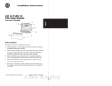
(Cat. No. 1794-OB8EP)
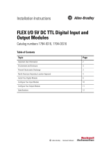
This module mounts on a 1794 terminal base unit.
1. Rotate keyswitch (1) on terminal base unit (2) clockwise to position 2
as required for this type of module.
2. Make certain the flexbus connector (3) is pushed all the way to the left
to connect with the neighboring terminal base/adapter. You cannot
install the module unless the connector is fully extended.
3. Make sure that the pins on the bottom of the module are straight so
they will align properly with the connector in the terminal base unit.
WARNING
!
If you remove or insert the module while the
backplane power is on, an electrical arc can occur.
This could cause an explosion in hazardous location
installations. Be sure that power is removed or the
area is nonhazardous before proceeding.
4. Position the module (4) with its alignment bar (5) aligned with the
groove (6) on the terminal base.
Installation Instructions

24V dc
FLEX I/O Electronically Fused 8 Output Module2
5. Press firmly and evenly to seat the module in the terminal base unit.
The module is seated when the latching mechanism (7) is locked into
the module.
Because of the variety of uses for the products described in this publication, those
responsible for the application and use of these products must satisfy themselves
that all necessary steps have been taken to assure that each application and use
meets all performance and safety requirements, including any applicable laws,
regulations, codes and standards. In no event will Allen–Bradley be responsible or
liable for indirect or consequential damage resulting from the use or application of
these products.
Any illustrations, charts, sample programs, and layout examples shown in this
publication are intended solely for purposes of example. Since there are many
variables and requirements associated with any particular installation,
Allen–Bradley does not assume responsibility or liability (to include intellectual
property liability) for actual use based upon the examples shown in this publication.
Allen–Bradley publication SGI–1.1, Safety Guidelines for Application, Installation,
and Maintenance of Solid–State Control (available from your local Allen–Bradley
office), describes some important differences between solid–state equipment and
electromechanical devices that should be taken into consideration when applying
products such as those described in this publication.
Reproduction of the contents of this copyrighted publication, in whole or part,
without written permission of Rockwell Automation, is prohibited.
Throughout this publication, notes may be used to make you aware of safety
considerations. The following annotations and their accompanying statements help
you to identify a potential hazard. avoid a potential hazard, and recognize the
consequences of a potential hazard.
WARNING
!
Identifies information about practices or
circumstances that can cause an explosion in a
hazardous environment, which may lead to personal
injury or death, property damage, or economic loss.
ATTENTION
!
Identifies information about practices or
circumstances that can lead to personal injury or
death, property damage, or economic loss.

24V dc
FLEX I/O Electronically Fused 8 Output Module 3
IMPORTANT
Identifies information that is critical for successful
application and understanding of the product.
ATTENTION
!
Environment and Enclosure
This equipment is intended for use in a Pollution Degree 2
industrial environment, in overvoltage Category II
applications (as defined in IEC publication 60664–1), at
altitudes up to 2000 meters without derating.
This equipment is considered Group 1, Class A industrial
equipment according to IEC/CISPR Publication 11.
Without appropriate precautions, there may be potential
difficulties ensuring electromagnetic compatibility in other
environments due to conducted as well as radiated
disturbance.
This equipment is supplied as “open type” equipment. It
must be mounted within an enclosure that is suitably
designed for those specific environmental conditions that
will be present, and appropriately designed to prevent
personal injury resulting from accessibility to live parts.
The interior of the enclosure must be accessible only by
the use of a tool. Subsequent sections of this publication
may contain additional information regarding specific
enclosure type ratings that are required to comply with
certain product safety certifications.
See NEMA Standards publication 250 and IEC publication
60529, as applicable, for explanations of the degrees of
protection provided by different types of enclosures. Also,
see the appropriate sections in this publication, as well as
the Allen–Bradley publication 1770–4.1, (“Industrial
Automation Wiring and Grounding Guidelines”), for
additional installation requirements pertaining to this
equipment.

24V dc
FLEX I/O Electronically Fused 8 Output Module4
ATTENTION
!
FLEX I/O is grounded through the DIN rail to
chassis ground. Use zinc plated, yellow chromated
steel DIN rail to assure proper grounding. Using
other DIN rail materials (e.g. aluminum, plastic, etc.)
which can corrode, oxidize or are poor conductors
can result in improper or intermittent platform
grounding.
!
ATTENTION
This equipment is sensitive to electrostatic discharge,
which can cause internal damage and affect normal
operation. Follow these guidelines when you handle
this equipment:
• Touch a grounded object to discharge potential
static.
• Wear an approved grounding wriststrap.
• Do not touch connectors or pins on component
boards.
• Do not touch circuit components inside the
equipment.
• If available, use a static–safe workstation.
• When not in use, keep modules in appropriate
static–safe packaging.
!
ATTENTION
Remove field-side power before removing or
inserting this module. This module is designed so
you can remove and insert it under backplane
power. When you remove or insert a module with
field-side power applied, an electrical arc may occur.
An electrical arc can cause personal injury or
property damage by:
• sending an erroneous signal to your system’s field
devices causing unintended machine motion
• causing an explosion in a hazardous environment
Repeated electrical arcing causes excessive wear to
contacts on both the module and its mating
connector. Worn contacts may create electrical
resistance.

24V dc
FLEX I/O Electronically Fused 8 Output Module 5
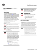
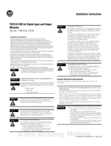
Wiring to a 1794ĆTB2, ĆTB3 or ĆTB3S Terminal Base Unit
WARNING
!
If you connect or disconnect wiring while the
fieldside power is on, an electrical arc can occur.
This could cause an explosion in hazardous location
installations. Be sure that power is removed or the
area is nonhazardous before proceeding.
1. Connect individual output wiring (customer loads) to even-numbered
terminals 0 through 14 on the 0 to 15 row (A).
2. Connect the associated return to the corresponding terminal on the
16–33 row (B) or to the odd-numbered terminals on the 0–15 row (A)
as indicated in the wiring table below. (Returns are internally
connected together.)
3. Connect +24V dc power to terminal 34 on the 34–51 row (C).
4. If continuing power to the next terminal base unit, connect a jumper
from terminal 51 (+24V dc) on this base unit to terminal 34 on the
next base unit.
5. Connect 24V dc return to terminal 16 on the 16–33 row (B).
6. If continuing 24V return to the next terminal base unit, connect a
jumper from terminal 33 (return) on this base unit to terminal 16 on
the next base unit.
1794ĆTB3
0 -15
34-51
16-33
A
B
C

24V dc
FLEX I/O Electronically Fused 8 Output Module6
Publication 1794-IN020B-EN-P - May 2002
0 1 2 3 4 5 6 7 8 9 10 11 12 13 14 15
18 19 20 21 22 23 3324 25 26 27 28 29 30 31 3217
35 36 37 38 47 48 49 5034
51
16
Label placed at top of wiring area.
Row A
Row B
Row C
Row A
Row B
Row C
39 40 41 42 43 44 45 46
0 AĆ0 AĆ1
1
/BĆ17
1 AĆ2 AĆ3
1
/BĆ19
2 AĆ4 AĆ5
1
/BĆ21
3 AĆ6 AĆ7
1
/BĆ23
4 AĆ8 AĆ9
1
/BĆ25
5 AĆ10 AĆ11
1
/BĆ27
6 AĆ12 AĆ13
1
/BĆ29
7 AĆ14 AĆ15
1
/BĆ31
A = output terminals
B = common terminals
C = Power terminals (CĆ34 thru 51 for 1794ĆTB3)
1
AĆ1, 3, 5, 7, 9, 11, 13 and 15 are connected together inside the module to 24V dc common.
!
ATTENTION
Total current draw through the terminal base unit is
limited to 10A. Separate power connections to the
terminal base unit may be necessary.

24V dc
FLEX I/O Electronically Fused 8 Output Module 7
'&"! *
Wiring to a 1794ĆTBN Terminal Base Unit
WARNING
!
If you connect or disconnect wiring while the
fieldside power is on, an electrical arc can occur.
This could cause an explosion in hazardous location
installations. Be sure that power is removed or the
area is nonhazardous before proceeding.
1. Connect individual output wiring (customer loads) to even numbered
terminals (0 thru 14) on row (B).
2. Connect customer load returns to odd numbered terminals (1 thru 15)
on row (C) as indicated in the table below.
3. Connect 24V dc return to terminal 16 on row (B).
4. If continuing the dc return bus to the next terminal base unit, connect
a jumper from terminal 33 on this base unit to terminal 16 on the next
base unit.
5. Connect +24V dc power to terminal 34 on row (C).
6. If continuing dc power to the next terminal base unit, connect a
jumper from terminal 51 (+24V dc) to terminal 34 on the next base
unit.
16, 0, 2, 4, 6,
8, 10, 12, 14, 33
34, 1, 3, 5, 7,
9, 11, 13, 15, 51
C
B
1794ĆTBN
(! ' $ $ !% &$'
' $ $ !% &$'
1794ĆTBN
Output Terminal Common Terminal
+ +
+ +
+ +
+ +
+ +
+ +
+ +
+ +
(! !' $ "'&#'& &$ !% &$' " "! &$ !% !
")$ $ !% + ! + ! " !' $ "'&#'& " "! &$ !% &$'

24V dc
FLEX I/O Electronically Fused 8 Output Module8
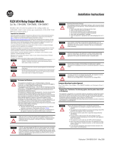
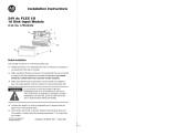
&"! %!$# '
2
= Status Indicators () – yellow – show status of individual outputs.
= Diagnostic indicators () – red – when lit, indicates fault
= Insertable label for writing input designations
= Reset button – press to reset fault
Faults can be reset 3 ways:
• press the fault reset button
• toggle the output reset bit (write word 1, bit 08)
• cycle backplane power
The reset function resets all output fault bits simultaneously. Non-faulted
outputs remain unaffected during the reset
Using the Fault Reset Button
When you press the manual reset button:
• the fault indicator for the faulted output turns off for about 1.2s (the
faulted output will not attempt to turn on during this delay)
• after the 1.2s delay, the faulted output attempts to turn on
• if the external condition causing the fault is corrected, the output will
remain on, the fault indicator is off, and the status indicator is on

24V dc
FLEX I/O Electronically Fused 8 Output Module 9
Publication 1794-IN020B-EN-P - May 2002
Image Table Mapping
Decimal Bits
15 14 13 12 11 10 09 08 07 06 05 04 03 02 01 00
IW F7 F6 F5 F4 F3 F2 F1 F0
Reserved (see note)
OW Not used FR O7 O6 O5 O4 O3 O2 O1 O0
OW2 Reserved
Where: IW = input word
OW = output word
F = overload fault bits-1=fault present;0=nofault
O = output data (O0 corresponds to output 0, O1 corresponds to output 2, etc.)
FR = fault reset bit-1=reset output;0=nochange.
Note: The unused lower byte in read word 1 floats during operation. Do not use this byte for fault
status. See Programming" below.
Programming
If your program automatically checks for fault bits, bits 8 through 15 of
read word 1 must be masked. This is a sample program for a module at
rack address 1, group 0. Add similar rungs to your program.
MVM
MASKED MOVE
Source:
Mask:
Destination:
I:010
FF00
N9:0
CMP
Compare
Expression
N9:0<>0
Out(
)
O:000
This rung masked bits 8 thru 15.
This rung turns on output if a fault occurs.

24V dc
FLEX I/O Electronically Fused 8 Output Module10
Publication 1794-IN020B-EN-P - May 2002
The following information applies when operating this equipment in hazardous
locations:
Products marked CL I, DIV 2, GP A, B, C, D" are suitable for use in Class I Division 2 Groups A, B, C,
and D Hazardous Locations and nonhazardous locations only. Each product is supplied with markings
on the rating nameplate indicating the hazardous location temperature code. When combining products
within a system, the most adverse temperature code (lowest T" number) may be used to help
determine the overall temperature code of the system. Combinations of equipment in your system are
subject to investigation by the local Authority Having Jurisdiction at the time of installation.
!
WARNING
EXPLOSION HAZARD -
• Do not disconnect equipment unless power has been removed or the
area is known to be nonhazardous.
• Do not disconnect connections to this equipment unless power has
been removed or the area is known to be nonhazardous. Secure any
external connections that mate to this equipment by using screws,
sliding latches, threaded connectors, or other means provided with this
product.
• Substitution of components may impair suitability for Class I, Division 2.
• If this product contains batteries, they must only be changed in an area
known to be nonhazardous.
Informations sur l'utilisation de cet équipement en environnements dangereux:
Les produits marqués CL I, DIV 2, GP A, B, C, D ne conviennent que une utilisation en environnements
de Classe I Division 2 Groupes A, B, C, D dangereux et non dangereux. Chaque produit est livré avec
des marquages sur sa plaque d'identification qui indiquent le code de température pour les
environnements dangereux. Lorsque plusieurs produits sont combinés dans un systéme, le code de
température le plus défavorable (code de température le plus faible) peut eatre utilisé pour déterminer
le code de température global du systéme. Les combinaisons d'equipements dans le systéme sont
sujettes à inspection par les autorités locales qualifiées au moment de l'installation.
!
AVERTISSEMENT
!
RISQUE D'EXPLOSION -
• Couper le courant ou s'assurer que l'environnement est classé non
dangereux avant de débrancher l'équipement.
• Couper le courant ou s'assurer que l'environnement est classé non
dangereux avant de débrancher les connecteurs. Fixer tous les
connecteurs externes reliés à cet équipement à l'aide de vis, loquets
coulissants, connecteurs filetés ou autres moyens fournis avec ce
produit.
• La substitution de composants peut rendre cet équipement inadapté à
une utilisation en environnement de Classe 1, Division 2.
• S'assurer que l'environnement est classé non dangereux avant de
changer les piles.

24V dc
FLEX I/O Electronically Fused 8 Output Module 11
Publication 1794-IN020B-EN-P - May 2002
"
Number of Outputs 8 (1 group of 8), nonĆisolated, sourcing
Module Location Cat. No. 1794ĆTB3, ĆTB3S, and ĆTBN Terminal Base
ONĆstate Voltage Range 19.2V dc minimum
24V dc nominal;
31.2V dc maximum
Output Current Rating Maximum 2.0A per output
10A maximum per module (e.g. 8 outputs @ 1.25A, 5
outputs @ 2.0A, or similar output/ampere combinations
totaling 10A or less)
OFFĆstate Voltage 31.2V dc maximum
ONĆstate Current 1.0mA minimum per channel
2.0A maximum per channel
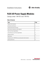
Surge Current 4A for 10ms, repeatable every 3 seconds (see chart)
OFFĆstate Leakage 0.5mA maximum
ONĆstate Voltage Drop 0.2V dc maximum
Isolation Voltage (minimum) Tested to 850V dc for 1s between user and system
No isolation between individual channels
Output Signal Delay
1
Off to On
OntoOff
0.1ms maximum
0.1ms maximum
Flexbus Current (maximum) 73mA
Power Dissipation 5.5W maximum @ 31.2V
Thermal Dissipation 18.8 BTU/hr @ 31.2V dc
Indicators (field side
indication, logic driven)
8 yellow status indicators;
8 red fault indicators
Keyswitch Position 2
External dc Power
Supply Voltage
Voltage Range
Supply Current
24V dc nominal
19.2 to 31.2V dc (includes 5% ac ripple)
80mA @ 24V dc
Dimensions Inches
(Millimeters)
1.8H x 3.7W x 2.1D
(45.7 x 94.0 x 53.3)
!

24V dc
FLEX I/O Electronically Fused 8 Output Module12
Publication 1794-IN020B-EN-P - May 2002
Conductors Wire Size
Category
12 gauge (4mm
2
) maximum stranded copper wire rated at
75
o
C or greater
3/64 inch (1.2mm) insulation maximum
2
2
Environmental Conditions
Operating
Temperature
IEC 60068-2-1 (Test Ad, Operating Cold)
IEC 60068-2-2 (Test Bd, Operating Dry Heat)
IEC 60068-2-14 (Test Nb, Operating Thermal Shock)
32 to 131°F(0to55°C)
Storage Temperature IEC 60068-2-1 (Test Ab, Unpackaged, Nonoperating Cold)
IEC 60068-2-2 (Test Bb, Unpackaged, Nonoperating Dry
Heat)
IEC 60068-2-14 (Test Na, Unpackaged, Nonoperating
Thermal Shock)
-40 to 185°F (-40 to 85°C)
Relative Humidity IEC 60068-2-30 (Test Db, Unpackaged, Nonoperating
Damp Heat)
5 to 95%, noncondensing
Shock
Operating
Nonoperating
IEC 60068-2-27 (Test Ea, Unpackaged Shock)
30g
50g
Vibration IEC 60068-2-6 (Test Fc, Operating)
5g @ 10-500Hz
ESD Immunity IEC 61000-4-2
4kV contact discharges
8kV air discharges
Radiated RF Immunity IEC 61000-4-3
10V/m with 1kHz sine-wave 80% AM from 30MHz to
1000MHz
EFT/B Immunity IEC 61000-4-4
+2kV @ 5kHz on signal ports
Surge Transient Immunity IEC 61000-4-5
+
1kV line-line (DM) and +2kV line-earth (CM) on signal
ports
Conducted RF Immunity IEC 61000-4-6
10V rms with 1kHz sine wave 80% AM from 150kHz to
80MHz
Emissions CISPR 11
Group 1, Class A (with appropriate enclosure)

24V dc
FLEX I/O Electronically Fused 8 Output Module 13
Publication 1794-IN020B-EN-P - May 2002
! ! ! "
Enclosure Type Rating None (open-style)
Agency Certification
(when product is marked)
UL UL Listed Industrial Control Equipment
CSA CSA Certified Process Control Equipment
CSA CSA Certified Process Control Equipment for
Class I, Division 2 Group A, B, C, D Hazardous
Locations
EEx
3
European Union 94/9/EEC ATEX Directive,
compliant with EN 50021; Potentially Explosive
Atmospheres, Protection n"
CE
3
European Union 89/336/EEC EMC Directive,
compliant with:
EN 61000-6-4, Industrial Emissions
EN 50082-2, Industrial Immunity
EN 61326, Meas./Control/Lab., Industrial
Requirements
EN 61000-6-2, Industrial Immunity
C-Tick
3
Australian Radiocommunications Act,compliant
- with AS/NZS 2064, Industrial Emissions
1
Off/on delay is time from a valid output on" signal to output energization. On/off delay is time from
a valid output off" signal to output deenergization.
2
You use this conductor category information for planning conductor routing as
described in the system level installation manual.
3
See the Product Certification link at www.ab.com for Declarations of Conformity, Certificates and other
certification details
0
5
10
15
20
0 1020304050
! ! ! ! !
"

24V dc
FLEX I/O Electronically Fused 8 Output Module14
Publication 1794-IN020B-EN-P - May 2002
This equipment is intended for use in potentially explosive atmospheres as defined by
European Union Directive 94/9/EC.
The LCIE (Laboratoire Central des Industries Electriques) certifies that this equipment has
been found to comply with the Essential Health and Safety Requirements relating to the
design and construction of Category 3 equipment intended for use in potentially explosive
atmospheres, given in Annex II to this Directive. The examination and test results are
recorded in confidential report No. 28 682 010.
Compliance with the Essential Health and Safety Requirements has been assured by
compliance with EN 50021 (1999).
IMPORTANT
Observe the following additional Zone 2 certification requirements:
• This equipment is not resistant to sunlight or other sources of UV
radiation.
• The secondary of a current transformer shall not be open-circuited
when applied in Class I, Zone 2 environments.
• Equipment of lesser Enclosure Type Rating must be installed in an
enclosure providing at least IP54 protection when applied in Class
I, Zone 2 environments.
• This equipment shall be used within its specified ratings defined by
Allen-Bradley.
• Provision shall be made to prevent the rated voltage from being
exceeded by transient disturbances of more than 40% when
applied in Class I, Zone 2 environments.

24V dc
FLEX I/O Electronically Fused 8 Output Module 15

24V dc
FLEX I/O Electronically Fused 8 Output Module16
Publication 1794-IN020B-EN-P - May 2002
With major offices worldwide.
World Headquarters,
AllenĆBradley,
1201 South Second Street,
Milwaukee, WI 53204 USA,
Tel: (1) 414 382Ć2000 Fax: (1) 414 382Ć4444
1794-IN020B-EN-P - May 2002
Supersedes publication1794Ć5.20 - April 1999
PN957678-95
Copyright 2002 AllenĆBradley Company, Inc. Printed in USA
/