
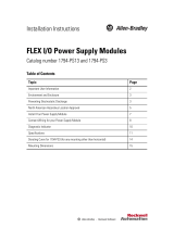
Installation Instructions
FLEX I/O 5V DC TTL Digital Input and
Output Modules
Catalog numbers 1794-IG16, 1794-OG16
Table of Contents
Topic Page
Important User Information 2
Environment and Enclosure 3
Prevent Electrostatic Discharge 3
North American Hazardous Location Approval 4
Install Your Digital Module 6
Configure Your Input Module 10
Configure Your Output Module 11
Specifications 12

2 FLEX I/O 5V DC TTL Digital Input and Output Modules
Publication 1794-IN119C-EN-P - August 2018
Important User Information
Solid-state equipment has operational characteristics differing from those of electromechanical
equipment. Safety Guidelines for the Application, Installation, and Maintenance of Solid-State Controls
(Publication SGI-1.1
available from your local Rockwell Automation Sales Office or online at
http://www.rockwellautomation.com/literature/
) describes some important differences between
solid-state equipment and hard-wired electromechanical devices. Because of this difference, and also
because of the wide variety of uses for solid-state equipment, all persons responsible for applying this
equipment must satisfy themselves that each intended application of this equipment is acceptable.
In no event will Rockwell Automation, Inc. be responsible or liable for indirect or consequential damages
resulting from the use or application of this equipment.
The examples and diagrams in this manual are included solely for illustrative purposes. Because of the
many variables and requirements associated with any particular installation, Rockwell Automation, Inc.
cannot assume responsibility or liability for actual use based on the examples and diagrams.
No patent liability is assumed by Rockwell Automation, Inc. with respect to use of information, circuits,
equipment, or software described in this manual.
Reproduction of the contents of this manual, in whole or in part, without written permission of Rockwell
Automation, Inc., is prohibited.
Throughout this manual, when necessary, we use notes to make you aware of safety considerations.
WARNING: Identifies information about practices or circumstances that can cause an
explosion in a hazardous environment, which may lead to personal injury or death,
property damage, or economic loss.
ATTENTION: Identifies information about practices or circumstances that can lead to
personal injury or death, property damage, or economic loss. Attentions help you
identify a hazard, avoid a hazard, and recognize the consequences.
SHOCK HAZARD: Labels may be on or inside the equipment (for example, drive or
motor) to alert people that dangerous voltage may be present.
BURN HAZARD: Labels may be on or inside the equipment (for example, drive or
motor) to alert people that surfaces may reach dangerous temperatures.
IMPORTANT Identifies information that is critical for successful application and understanding of
the product.

FLEX I/O 5V DC TTL Digital Input and Output Modules 3
Publication 1794-IN119C-EN-P - August 2018
Environment and Enclosure
Prevent Electrostatic Discharge
ATTENTION: This equipment is intended for use in a Pollution Degree 2
industrial environment, in overvoltage Category II applications (as defined in
EN/IEC 60664-1), at altitudes up to 2000 m (6562 ft) without derating.
This equipment is not intended for use in residential environments and may not
provide adequate protection to radio communication services in such
environments.
This equipment is supplied as open-type equipment for indoor use. It must be
mounted within an enclosure that is suitably designed for those specific
environmental conditions that will be present and appropriately designed to
prevent personal injury resulting from accessibility to live parts. The enclosure
must have suitable flame-retardant properties to prevent or minimize the spread
of flame, complying with a flame spread rating of 5VA or be approved for the
application if nonmetallic. The interior of the enclosure must be accessible only
by the use of a tool. Subsequent sections of this publication may contain more
information regarding specific enclosure type ratings that are required to
comply with certain product safety certifications.
In addition to this publication, see the following:
• Industrial Automation Wiring and Grounding Guidelines, publication
1770-4.1
, for more installation requirements.
• NEMA Standard 250 and EN/IEC 60529, as applicable, for explanations of
the degrees of protection provided by enclosures.
ATTENTION: This equipment is sensitive to electrostatic discharge, which can
cause internal damage and affect normal operation. Follow these guidelines
when you handle this equipment:
• Touch a grounded object to discharge potential static.
• Wear an approved grounding wriststrap.
• Do not touch connectors or pins on component boards.
• Do not touch circuit components inside the equipment.
• Use a static-safe workstation, if available.
• Store the equipment in appropriate static-safe packaging when not in use.

4 FLEX I/O 5V DC TTL Digital Input and Output Modules
Publication 1794-IN119C-EN-P - August 2018
North American Hazardous Location Approval
The following modules are North American Hazardous Location approved: 1794-IG16,
1794-OG16.
The following information applies when
operating this equipment in hazardous
locations:
Informations sur l’utilisation de cet équipement
en environnements dangereux:
Products marked "CL I, DIV 2, GP A, B, C, D" are suitable
for use in Class I Division 2 Groups A, B, C, D, Hazardous
Locations and nonhazardous locations only. Each product
is supplied with markings on the rating nameplate
indicating the hazardous location temperature code.
When combining products within a system, the most
adverse temperature code (lowest "T" number) may be
used to help determine the overall temperature code of
the system. Combinations of equipment in your system
are subject to investigation by the local Authority Having
Jurisdiction at the time of installation.
Les produits marqués "CL I, DIV 2, GP A, B, C, D" ne conviennent
qu'à une utilisation en environnements de Classe I Division 2
Groupes A, B, C, D dangereux et non dangereux. Chaque produit
est livré avec des marquages sur sa plaque d'identification qui
indiquent le code de température pour les environnements
dangereux. Lorsque plusieurs produits sont combinés dans un
système, le code de température le plus défavorable (code de
température le plus faible) peut être utilisé pour déterminer le
code de température global du système. Les combinaisons
d'équipements dans le système sont sujettes à inspection par
les autorités locales qualifiées au moment de l'installation.
EXPLOSION HAZARD
• Do not disconnect equipment unless
power has been removed or the area is
known to be nonhazardous.
• Do not disconnect connections to this
equipment unless power has been
removed or the area is known to be
nonhazardous. Secure any external
connections that mate to this equipment
by using screws, sliding latches,
threaded connectors, or other means
provided with this product.
• Substitution of components may impair
suitability for Class I, Division 2.
RISQUE D’EXPLOSION
• Couper le courant ou s'assurer que
l'environnement est classé non dangereux
avant de débrancher l'équipement.
• Couper le courant ou s'assurer que
l'environnement est classé non dangereux
avant de débrancher les connecteurs. Fixer
tous les connecteurs externes reliés à cet
équipement à l'aide de vis, loquets
coulissants, connecteurs filetés ou autres
moyens fournis avec ce produit.
• La substitution de composants peut rendre cet
équipement inadapté à une utilisation en
environnement de Classe I, Division 2.
IMPORTANT
To comply with North American restrictions, all connected I/O must be
powered from a source compliant with the following: Class 2
ATTENTION: This product is grounded through the DIN rail to chassis ground.
Use zinc plated chromate-passivated steel DIN rail to assure proper grounding.
The use of other DIN rail materials (for example, aluminum or plastic) that can
corrode, oxidize, or are poor conductors, can result in improper or intermittent
grounding. Secure DIN rail to mounting surface approximately every 200 mm
(7.8 in.) and use end-anchors appropriately. Be sure to ground the DIN rail
properly. Refer to Industrial Automation Wiring and Grounding Guidelines,
Rockwell Automation publication 1770-4.1
, for more information.

FLEX I/O 5V DC TTL Digital Input and Output Modules 5
Publication 1794-IN119C-EN-P - August 2018
ATTENTION: If this equipment is used in a manner not specified by the
manufacturer, the protection provided by the equipment may be impaired.
ATTENTION: Read this document and the documents listed in the Additional
Resources section about installation, configuration, and operation of this
equipment before you install, configure, operate, or maintain this product. Users
are required to familiarize themselves with installation and wiring instructions
in addition to requirements of all applicable codes, laws, and standards.
ATTENTION: Installation, adjustments, putting into service, use, assembly,
disassembly, and maintenance are required to be carried out by suitably trained
personnel in accordance with applicable code of practice.
ATTENTION: In case of malfunction or damage, no attempts at repair should be
made. The module should be returned to the manufacturer for repair. Do not
dismantle the module.
ATTENTION: This equipment is certified for use only within the surrounding air
temperature range of 0…55 °C (32…131 °F). The equipment must not be used
outside of this range.
ATTENTION: Use only a soft dry anti-static cloth to wipe down equipment. Do
not use any cleaning agents.
WARNING: When you insert or remove the module while backplane power is
on, an electric arc can occur. This could cause an explosion in hazardous
location installations.
Be sure that power is removed or the area is nonhazardous before proceeding.
Repeated electric arcing causes excessive wear to contacts on both the module
and its mating connector. Worn contacts may create electrical resistance that
can affect module operation.
WARNING: If you insert or remove the module while backplane power is on, an
electrical arc can occur. This could cause an explosion in hazardous location
installations.
Be sure that power is removed or the area is nonhazardous before proceeding.

6 FLEX I/O 5V DC TTL Digital Input and Output Modules
Publication 1794-IN119C-EN-P - August 2018
Install Your Digital Module
WARNING: Do not connect control circuit directly to line voltage. Line voltage
must be supplied by a suitable, approved isolating transformer or power supply
having short circuit capacity not exceeding 100 VA maximum or equivalent.
WARNING: If you connect or disconnect wiring while the field-side power is
on, an electrical arc can occur. This could cause an explosion in hazardous
location installations.
Be sure that power is removed or the area is nonhazardous before proceeding.
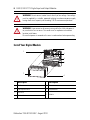
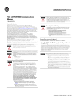
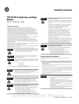
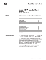
Description Description
1 FlexBus connectors 5 Groove
2 Latching mechanism 6 Alignment bar
3 Keyswitch
7
Module
4 Terminal base
6
1
7
5
4
3
2
45284

FLEX I/O 5V DC TTL Digital Input and Output Modules 7
Publication 1794-IN119C-EN-P - August 2018
The module mounts on a 1794 terminal base.
1. Rotate the keyswitch (3) on the terminal base (4) clockwise to position 1 as
required for this type of module.
2. Make sure the FlexBus connector (1) is pushed all the way to the left to connect
with the neighboring terminal base/adapter. You cannot install the module
unless the connector is fully extended.
3. Make sure the pins on the bottom of the module are straight so they will align
properly with the connector in the terminal base.
4. Position the module (7) with its alignment bar (6) aligned with the groove (5) on
the terminal base.
5. Press firmly and evenly to seat the module in the terminal base unit. The module
is seated when the latching mechanism (2) is locked into the module.
Connect Wiring for Your Module
(using a 1794-TB3 or 1794-TB3S Terminal Base)
1. Connect individual input or output wiring to numbered terminals on the 0-15
row (A) as indicated in the Wiring Connections for 1794-IG16 and 1794-OG16
table.
2. Connect the associated input and output devices as indicated in the wiring
diagrams.
3. Connect +V DC power to terminal 34 on the 34-51 row (C).
ATTENTION: Do not remove or replace a Terminal Base unit when power is
applied. Interruption of the backplane can result in unintentional operation or
machine motion.
ATTENTION: During mounting of all devices, be sure that all debris (metal
chips, wire strands, etc.) is kept from falling into the module. Debris that falls
into the module could cause damage on power up.
WARNING: When used in a Class I, Division 2, hazardous location, this
equipment must be mounted in a suitable enclosure with proper wiring method
that complies with the governing electrical codes.

8 FLEX I/O 5V DC TTL Digital Input and Output Modules
Publication 1794-IN119C-EN-P - August 2018
4. Connect DC common to terminal 16 on the 16-33 row (B).
5. If daisychaining power to the next terminal base, connect a jumper from terminal
51 (+V DC) on this base unit to terminal 34 on the next base unit.
6. If continuing DC common to the next base unit, connect a jumper from terminal
33 (common) on this base unit to terminal 16 on the next base unit.
Wiring Connections for 1794-IG16 and 1794-OG16
Channel Signal Power Terminal Common Terminal
0A-0C-35 B-17
1A-1C-36 B-18
2A-2C-37 B-19
3A-3C-38 B-20
4A-4C-39 B-21
5A-5C-40 B-22
6A-6C-41 B-23
7A-7C-42 B-24
8A-8C-43 B-25
9A-9C-44 B-26
10 A-10 C-45 B-27
11 A-11 C-46 B-28
12 A-12 C-47 B-29
13 A-13 C-48 B-30
14 A-14 C-49 B-31
15 A-15 C-50 B-32
+5V DC C-34...C-51 are internally connected together
Common B-16...B-33 are internally connected together

FLEX I/O 5V DC TTL Digital Input and Output Modules 9
Publication 1794-IN119C-EN-P - August 2018
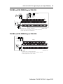
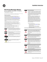
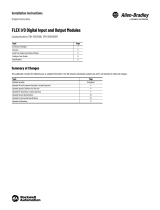
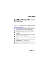
1794-TB3 and 1794-TB3S Wiring for 1794-IG16
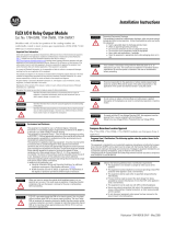
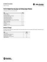
1794-TB3 and 1794-TB3S Wiring for 1794-OG16
16 17 18 19 20 21 22 23 24 25 26 27 28 29 30 31 32 33
0 1 2 3 4 5 6 7 8 9 10 11 12 13 14 15
34 35 36 37 38 39 40 41 42 43 44 45 46 47 48 49 50 51
Inputs
Commons
(1794-TB3 shown)
Use Belden 8761, or equivalent, shielded wire.
Capacitors shown must be 0.01µF and rated for 2000 Volts (minimum).
-V
Voltage
In +V
Voltage
Out +V
Voltage
A
B
C
I/O cable length must be less than 10 meters.
Common
-V
Common
I/O wire
TTL input device
Capacitor
0.01
µ
F typical
+
-
*
+
-
*
DC power
wire
I/O wire
5
V
D
C
p
o
w
e
r
16 17 18 19 20 21 22 23 24 25 26 27 28 29 30 31 32 33
0 1 2 3 4 5 6 7 8 9 10 11 12 13 14 15
34 35 36 37 38 39 40 41 42 43 44 45 46 47 48 49 50 51
Outputs
Commons
(1794-TB3 shown)
Use Belden 8761, or equivalent, shielded wire.
Capacitors shown must be 0.01µF and rated for 2000 Volts (minimum).
-V
Voltage
In +V
Voltage
Out +V
Voltage
A
B
C
I/O cable length must be less than 10 meters.
Common
-V
Common
TTL
output
device
Capacitor
0.01
µ
F typical
*
+
-
*
DC power
wire
I/O wire
5
V
D
C
p
o
w
e
r
+
-
L

10 FLEX I/O 5V DC TTL Digital Input and Output Modules
Publication 1794-IN119C-EN-P - August 2018
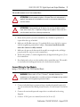
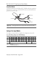
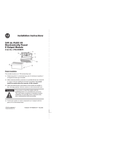
Ground Your Module
Use shielded communication cable (Belden #8761). The Belden cable has two signal wires
(black and clear), one drain wire, and a foil shield. The drain wire and foil shield must be
grounded at one end of the cable.
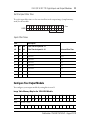
Configure Your Input Module
You configure your input module by setting bits in the configuration word (word 3).
IMPORTANT
Do not ground the drain wire and foil shield at both ends of the cable.
Image Table Memory Map for the 1794-IG16 Module
Dec 1514131211109876543210
Oct 17161514131211107 6 5 4 3 2 1 0
Read I15
I14I13I12I11I10I9I8I7I6I5I4I3I2I1I0
Write Not used - set to 0 Input Filter FT1
12...15
Input Filter FT0
0...11
Where I = Input status
FT0 = Input filter time for inputs 0...1
FT1 = Input filter time for inputs 12...15
Foil shield
Black wire
Drain wire
Clear wire
Insulation

FLEX I/O 5V DC TTL Digital Input and Output Modules 11
Publication 1794-IN119C-EN-P - August 2018
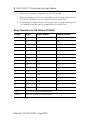
Set the Input Filter Time
To set the input filter time, set the associated bits in the output image (complementary
word) for the module.
Input Filter Times
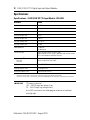
Configure Your Output Module
You configure your output module by setting bits in word 1.
Bits Description
Selected Filter Time
02 01 00 Filter Time for inputs 00...11
05 04 03 Filter Time for inputs 12...15
000Filter Time 0 (Default) 0.25 ms
001Filter Time 1 0.5 ms
010Filter Time 2 1 ms
011Filter Time 3 2 ms
101Filter Time 4 4 ms
101Filter Time 5 8 ms
110Filter Time 6 16 ms
111Filter Time 7 32 ms
Image Table Memory Map for the 1794-OG16 Module
Dec 1514131211109876543210
Oct 17161514131211107 6 5 4 3 2 1 0
Read Not used – set to 0
Write O15O14O13O12O11O10O9O8O7O6O5O4O3O2O1O0
Where O = Output
O:010
09 08 07 06 05 04 03 02 01
00
15 14 13 12 11 10
Dec.
FT = 12 thru 15
FT = 00 thru 11

12 FLEX I/O 5V DC TTL Digital Input and Output Modules
Publication 1794-IN119C-EN-P - August 2018
Specifications
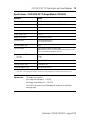
Specifications – FLEX I/O 5V DC TTL Input Module 1794-IG16
Attribute Value
Number of inputs 16, TTL
Recommended terminal base unit 1794-TB3, 1794-TB3S, 1794-TB3K, 1794-TB3SK, 1794-TBKD
On-state voltage, min 0.2V DC
On-state voltage, nom 0V DC
On-state voltage, max 0.8V DC
Off-state voltage, max 2...5.5V DC
Off-state current, max 4.1 mA
Input impedance 1.4 kΩ min
1.5 kΩ typical
Isolation voltage 50V (continuous), Basic Insulation Type,
Type tested @ 707V DC for 60 s, between field side and system
No isolation between individual channels
Input filter time
(1)
Off to On
On to Off
(1)
Input off-to-on filter time is the time from a valid input signal to recognition by the module.
Input on-to-off filter time is time from the input signal dropping below the valid level to recognition by the module.
Refer to Input Filter Times table
FlexBus current 40 mA @ 5V DC
Power dissipation, max 1.4 W @ 5.5V DC
Thermal dissipation, max 4.78 BTU/hr @ 5.5V DC
IMPORTANT
TTL inputs are inverted
(-0.2…0.8V DC=logic low voltage=1=on
2.0…5.5V DC=logic high voltage=0=off).
Use a NOT instruction in the ladder program to convert to traditional
true=High logic.

FLEX I/O 5V DC TTL Digital Input and Output Modules 13
Publication 1794-IN119C-EN-P - August 2018
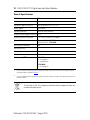
Specifications – FLEX I/O 5V DC TTL Output Module 1794-OG16
Attribute Value
Number of outputs 16, TTL
Recommended terminal base unit 1794-TB3, 1794-TB3S, 1794-TB3K, 1794-TB3SK
Output voltage, min 0V DC
Output voltage, nom 0V DC
Output voltage, max 0.4V DC
Output current rating 24 mA max per channel
On-state current 0.15 mA min per channel
24 mA max per channel
Off-state leakage, max 1 mA
Isolation voltage 50V (continuous), Basic Insulation Type
Type tested at 707V DC for 60 s, between field side and system
No isolation between individual channels
Output signal delay
(1)
Off to On
On to Off
0.5 ms
1.0 ms
FlexBus current 80 mA @ 5V DC
Power dissipation, max 0.8 W @ 5.5V DC
Thermal dissipation, max 3.41 BTU/hr @ 5.5V DC
(1)
Delay time is the time from the receipt of an output on or off command to the output actually turning on or off.
IMPORTANT
TTL outputs are inverted
(On=1=logic low voltage=0…0.4V DC;
Off=0=logic high voltage=4.5…5.5V DC).
Use a NOT instruction in the ladder program to convert to traditional
true=High logic.

14 FLEX I/O 5V DC TTL Digital Input and Output Modules
Publication 1794-IN119C-EN-P - August 2018
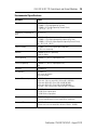
General Specifications
Attribute Value
Terminal base screw torque Determined by installed terminal base
Dimensions, approx. (H x W x D) 94 x 94 x 69 mm (3.7 x 3.7 x 2.7 in.)
Weight, approx. 76 g (2.68 oz.)
Indicators (field side) 16 yellow status indicators
External DC power supply voltage, nom 5V DC
External DC power voltage range 4.5...5.5V DC (includes 5% AC ripple)
External DC supply current range 210 mA @ 5V DC – 1794-IG16
100 mA @ 5V DC – 1794-OG16
North American temp code T4A
Keyswitch position 1
Enclosure type rating None (open-style)
Wire size Determined by installed terminal base
Wiring category
(1)
(2)
(1)
Use this Conductor Category information for planning conductor routing. Refer to Industrial Automation Wiring and
Grounding Guidelines, publication 1770-4.1.
(2)
Use this Conductor Category information for planning conductor routing as described in the appropriate System Level
Installation Manual.
(1794-IG16)
3 - on signal ports
2 - on power ports
(1794-OG16)
2 - on signal ports
At the end of its life, this equipment should be collected separately from any
unsorted municipal waste.

FLEX I/O 5V DC TTL Digital Input and Output Modules 15
Publication 1794-IN119C-EN-P - August 2018
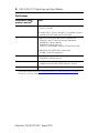
Environmental Specifications
Attribute Value
Temperature, operating IEC 60068-2-1 (Test Ad, Operating Cold),
IEC 60068-2-2 (Test Bd, Operating Dry Heat),
IEC 60068-2-14 (Test Nb, Operating Thermal Shock):
0…55 °C (32…131 °F)
Temperature, surrounding air,
max.
55 °C (131 °F)
Temperature, nonoperating IEC 60068-2-1 (Test Ab, Unpackaged Nonoperating Cold),
IEC 60068-2-2 (Test Bb, Unpackaged Nonoperating Dry Heat),
IEC 60068-2-14 (Test Na, Unpackaged Nonoperating Thermal Shock):
-40…85 °C (-40…185 °F)
Relative humidity IEC 60068-2-30 (Test Db, Unpackaged Damp Heat):
5…95% non-condensing
Vibration IEC60068-2-6 (Test Fc, Operating):
5 g @ 10...500 Hz
Shock, operating IEC60068-2-27 (Test Ea, Unpackaged shock):
30 g
Shock, nonoperating IEC60068-2-27 (Test Ea, Unpackaged shock):
50 g
Emissions IEC 61000-6-4
ESD immunity IEC 61000-4-2:
6 kV contact discharges
8 kV air discharges
Radiated RF immunity IEC 61000-4-3:
10V/m with 1 kHz sine-wave 80% AM from 80...2000 MHz
10V/m with 200 Hz 50% Pulse 100% AM @ 900 MHz
10V/m with 200 Hz 50% Pulse 100% AM @ 1890 MHz
1V/m with 1 kHz sine-wave 80% AM from 2000...2700 MHz
EFT/B immunity IEC 61000-4-4:
±2 kV @ 5 kHz on power ports
±2 kV @ 5 kHz on signal ports
Surge transient immunity IEC 61000-4-5:
±1 kV line-line(DM) and ±2 kV line-earth(CM) on signal ports
Conducted RF immunity IEC 61000-4-6:
10V rms with 1 kHz sine-wave 80% AM from 150 kHz…80 MHz

16 FLEX I/O 5V DC TTL Digital Input and Output Modules
Publication 1794-IN119C-EN-P - August 2018
Certifications
Certifications (when
product is marked)
(1)
Value
c-UL-us UL Listed Industrial Control Equipment, certified for US and Canada.
See UL File E322657.
UL Listed for Class I, Division 2, Group A, B, C, D Hazardous Locations,
certified for US and Canada. See UL File E334470.
CE European Union 2014/30/EU EMC Directive, compliant with:
EN 61326-1; Meas./Control/Lab., Industrial Requirements
EN 61000-6-2; Industrial Immunity
EN 61000-6-4; Industrial Emissions
EN 61131-2; Programmable Controllers (Clause 8, Zone A & B)
European Union 2011/65/EU RoHS, compliant with:
EN 50581; Technical Documentation
RCM Australian Radiocommunications Act, compliant with:
EN 61000-6-4; Industrial Emissions
KC Korean Registration of Broadcasting and Communications Equipment,
compliant with: Article 58-2 of Radio Waves Act, Clause 3
EAC Russian Customs Union TR CU 020/2011 EMC Technical Regulation
(1)
See the Product Certification link at http://www.rockwellautomation.com/global/certification/overview.page for
Declarations of Conformity, Certificates, and other certification details.

FLEX I/O 5V DC TTL Digital Input and Output Modules 17
Publication 1794-IN119C-EN-P - August 2018
Notes:

Rockwell Automation Support
Rockwell Automation provides technical information on the Web to assist you in using its products. At
http://www.rockwellautomation.com/support/
, you can find technical manuals, a knowledge base of FAQs,
technical and application notes, sample code and links to software service packs, and a MySupport feature
that you can customize to make the best use of these tools.
For an additional level of technical phone support for installation, configuration and troubleshooting, we
offer TechConnect support programs. For more information, contact your local distributor or Rockwell
Automation representative, or visit http://www.rockwellautomation.com/support/
.
Installation Assistance
If you experience a problem within the first 24 hours of installation, please review the information that's
contained in this manual. You can also contact a special Customer Support number for initial help in getting
your product up and running.
New Product Satisfaction Return
Rockwell Automation tests all of its products to ensure that they are fully operational when shipped from
the manufacturing facility. However, if your product is not functioning and needs to be returned, follow
these procedures.
Documentation Feedback
Your comments will help us serve your documentation needs better. If you have any suggestions on how to
improve this document, complete this form, publication RA-DU002
, available at
http://www.rockwellautomation.com/literature/
.
United States or Canada 1.440.646.3434
Outside United States or
Canada
Use the Worldwide Locator at
http://www.rockwellautomation.com/support/americas/phone_en.html
, or
contact your local Rockwell Automation representative.
United States Contact your distributor. You must provide a Customer Support case number
(call the phone number above to obtain one) to your distributor to complete
the return process.
Outside United States Please contact your local Rockwell Automation representative for the return
procedure.
Publication 1794-IN119C-EN-P - August 2018
Supersedes Publication 1794-IN119B-EN-P - August 2015 Copyright © 2018 Rockwell Automation, Inc. All rights reserved.
Allen-Bradley, Rockwell Automation, FLEX I/O, Rockwell Software, and TechConnect are trademarks of Rockwell Automation, Inc.
Trademarks not belonging to Rockwell Automation are property of their respective companies.
Rockwell Automation maintains current product environmental information on its website at
http://www.rockwellautomation.com/rockwellautomation/about-us/sustainability-ethics/product-environmental-compliance.page
.
-
 1
1
-
 2
2
-
 3
3
-
 4
4
-
 5
5
-
 6
6
-
 7
7
-
 8
8
-
 9
9
-
 10
10
-
 11
11
-
 12
12
-
 13
13
-
 14
14
-
 15
15
-
 16
16
-
 17
17
-
 18
18


Allen-Bradley FLEX I/O 1794-IG16 Installation Instructions Manual
- Taper
- Installation Instructions Manual
- Ce manuel convient également à
dans d''autres langues
- English: Allen-Bradley FLEX I/O 1794-IG16
Documents connexes
-
 Allen-Bradley FLEX I/O 1794-IG16 Guide d'installation
-
 Allen-Bradley FLEX I/O 1794-OM16 Installation Instructions Manual
-
 Allen-Bradley 1794-PS13 Installation Instructions Manual
-
 Allen-Bradley 1794-OB16 Installation Instructions Manual
-
 Allen-Bradley FLEX I/O 1794-APBDPV1 Guide d'installation
-
 Allen-Bradley FLEX I/O ControlNet D Series Installation Instructions Manual
-
 Allen-Bradley 1794-OW8 Guide d'installation
-
 Allen-Bradley FLEX I/O 1794-OB8EP Installation Instructions Manual
-
 Allen-Bradley FLEX I/O 1794-IR8 Installation Instructions Manual
-
 Allen-Bradley FLEX I/O 1794-IC16 Installation Instructions Manual


Autres documents
-
Allen Bradley 1794-PS13 Manuel utilisateur
-
 Allen Bradley Allen-Bradley 1794-IB10XOB6 FLEX I/O Digital Input/Output Module Manuel utilisateur
-
 Allen Bradley Allen-Bradley 1794-IV16 FLEX I-O Digital Sourcing Input and Sinking Output Modules Manuel utilisateur
-
 Rockwell Automation 1771-ID16 Installation Instructions Manual
-
 Rockwell Automation Micro800 2080-MEMBAK-RTC2 Guide de démarrage rapide
-
Spectrum Controls 1794sc-IF8IU Mode d'emploi
-


