
www.metabo.com Made in Germany
de Originalbetriebsanleitung 5
en Original instructions 11
fr Notice originale 16
nl Oorspronkelijke gebruiksaanwijzing 22
it Istruzioni originali 28
es Manual original 34
pt Manual original 40
sv Bruksanvisning i original 46
fi Alkuperäiset ohjeet 51
no Original bruksanvisning 56
da Original brugsanvisning 61
pl Instrukcja oryginalna 66
el Πρωτότυπες οδηγίες χρήσης 72
hu Eredeti használati utasítás 79
ru Оригинальное руководство по
эксплуатации 85
MAG 28 LTX 32

2
1
18
19
2
3
4
5
6
78 1091112
13
14
15
16
17
18
19
20
21
22
24
23
2526272829

3
MAG 28 LTX 32
UV
25,2
Li-Ion
T- MK2
MNm(in-lbs) 145 (1283)
D
max, K
mm (in)
32 (1
1
/
4
)
D
max, S
mm (in)
13 (
1
/
2
)
n
0
/min 380 / 680
H
max
mm (in)
160 (6
5
/
16
)
H
u
mm (in)
455 (17
29
/
32
)
H
o
mm (in)
615 (24
7
/
32
)
Amm (in)
70 (2
3
/
4
) x 190 (7
1
/
2
)
mkg(lbs) 16,5 (36.4)
L
pA
/K
pA
dB(A) 88 / 3
L
WA
/K
WA
dB(A) 101 / 3
13.
*2) 2011/65/EU 2006/42/EC 2004/108/EC
*3) EN 60745-1:2009+A11:2010, EN 61029-1:2009, EN 61029-2-6:2010
2015-03-04, Volker Siegle
Direktor Innovation, Forschung und Entwicklung
(Director Innovation, Research and Development)
*1) Serial Number: 00334..

4
Ø
T
HSS (T=55 mm); HM: 6.26609
HSS (T=30 mm): 6.26608
G
K
I
F
6.35115
6.35036
6.26604
6.26606
J
341148140
ASS 15 Plus 25,2 V 3,0 Ah 6.25437 Li-Power
etc
MK 2 B 16
MK 2
D
E
L
A
H
6.26602
MK 2
A
A
C
B
HSS „rapid cut“
T Ø Nr.
30 mm 14 mm 6.26542
30 mm 18 mm 6.26543
30 mm 22 mm 6.26544
30 mm 26 mm 6.26545
HSS
T Ø Nr.
30 mm 12 mm 6.26500
30 mm 13 mm 6.26501
30 mm 14 mm 6.26502
30 mm 15 mm 6.26503
30 mm 16 mm 6.26504
30 mm 17 mm 6.26505
30 mm 18 mm 6.26506
30 mm 19 mm 6.26507
30 mm 20 mm 6.26508
30 mm 21 mm 6.26509
30 mm 22 mm 6.26510
30 mm 23 mm 6.26511
30 mm 24 mm 6.26512
30 mm 25 mm 6.26513
30 mm 26 mm 6.26514
30 mm 27 mm 6.26515
30 mm 28 mm 6.26516
30 mm 29 mm 6.26517
30 mm 30 mm 6.26518
30 mm 31 mm 6.26519
30 mm 32 mm 6.26520
HSS
T Ø Nr.
55 mm 12 mm 6.26521
55 mm 13 mm 6.26522
55 mm 14 mm 6.26523
55 mm 15 mm 6.26524
55 mm 16 mm 6.26525
55 mm 17 mm 6.26526
55 mm 18 mm 6.26527
55 mm 19 mm 6.26528
55 mm 20 mm 6.26529
55 mm 21 mm 6.26530
55 mm 22 mm 6.26531
55 mm 23 mm 6.26532
55 mm 24 mm 6.26533
55 mm 25 mm 6.26534
55 mm 26 mm 6.26535
55 mm 27 mm 6.26536
55 mm 28 mm 6.26537
55 mm 29 mm 6.26538
55 mm 30 mm 6.26539
55 mm 31 mm 6.26540
55 mm 32 mm 6.26541
HM
T Ø Nr.
55 mm 14 mm 6.26571
55 mm 15 mm 6.26572
55 mm 16 mm 6.26573
55 mm 17 mm 6.26574
55 mm 18 mm 6.26575
55 mm 19 mm 6.26576
55 mm 20 mm 6.26577
55 mm 21 mm 6.26578
55 mm 22 mm 6.26579
55 mm 23 mm 6.26580
55 mm 24 mm 6.26581
55 mm 25 mm 6.26582
55 mm 26 mm 6.26583
55 mm 27 mm 6.26584
55 mm 28 mm 6.26585
55 mm 29 mm 6.26586
55 mm 30 mm 6.26587
55 mm 31 mm 6.26588
55 mm 32 mm 6.26589
55 mm 33 mm 6.26590
55 mm 34 mm 6.26591
55 mm 35 mm 6.26592
55 mm 36 mm 6.26593
55 mm 37 mm 6.26594
55 mm 38 mm 6.26595
55 mm 39 mm 6.26596
55 mm 40 mm 6.26597
55 mm 45 mm 6.26598
55 mm 50 mm 6.26599

DEUTSCH de
5
Originalbetriebsanleitung
Wir erklären in alleiniger Verantwortlichkeit: Diese
Akku-Magnetkernbohrmaschinen, identifiziert
durch Type und Seriennummer *1), entsprechen
allen einschlägigen Bestimmungen der Richtlinien
*2) und Normen *3). Technische Unterlagen bei *4)
- siehe Seite 3.
Die Magnet-Kernbohrmaschine ist geeignet zum
Kernbohren mit geeigneten Schneidwerkzeugen
und zum Bohren mit Spiralbohrern in Metall.
Der Magnet-Bohrständer ist bestimmt zum
Befestigen an ebenem und zylinderförmigem (mit
Durchmesser 90 - 300 mm), magnetisierbarem
Metall, er muss dabei einwandfrei haften.
Bei Verwendung des mitgelieferten Sicherungs-
gurts auch geeignet zum Arbeiten an schrägen und
senkrechten Flächen und über Kopf.
Für Schäden durch nicht bestimmungsgemäßen
Gebrauch haftet allein der Benutzer.
Allgemein anerkannte Unfallverhütungsvorschriften
und beigelegte Sicherheitshinweise müssen
beachtet werden.
WARNUNG – Zur Verringerung eines
Verletzungsrisikos Betriebsanleitung lesen.
WARNUNG Lesen Sie alle Sicherheits-
hinweise und Anweisungen. Versäumnisse
bei der Einhaltung der Sicherheitshinweise und
Anweisungen können elektrischen Schlag, Brand
und/oder schwere Verletzungen verursachen.
Bewahren Sie alle Sicherheitshinweise und
Anweisungen für die Zukunft auf.
Lesen Sie vor der Benutzung des Elektrowerkzeugs
die beiliegenden Sicherheitshinweise und die
Gebrauchsanleitung aufmerksam und vollständig
durch. Bewahren Sie alle beiliegenden Dokumente
auf und geben Sie Ihr Elektrowerkzeug nur
zusammen mit diesen Dokumenten weiter.
Beachten Sie die mit diesem Symbol
gekennzeichneten Textstellen zu Ihrem
eigenen Schutz und zum Schutz Ihres
Elektrowerkzeugs!
Zum Arbeiten an schrägen und senkrechten
Flächen und über Kopf muss der Magnet-
Bohrständer mit dem mitgelieferten
Sicherungsgurt
so gesichert werden, dass er bei
Versagen des Magneten nicht herunterfallen kann.
Bei Versagen des Magneten führt die Maschine
einen gefährlichen Pendelschlag aus.
Bei Überkopfarbeiten immer einen Schutzhelm
tragen.
Beim Arbeiten immer Schutzbrille,
Schutzhandschuhe und geeignetes Schuhwerk
tragen.
Durch den Magneten entstehen magnetische
Felder, die sich negativ auf medizinische Implantate
auswirken können.
Die Fläche für den Magneten muss sauber und
eben sein.
Die Magnet-Haltekraft ist abhängig von
Materialstärke und Beschaffenheit.
Farb-, Zink- und Zunderschichten reduzieren die
Magnet-Haltekraft.
Die Maschine nicht dem Regen aussetzen und
nicht in nassen oder explosionsgefährdeten
Räumen verwenden.
Befolgen Sie die Hinweise zur Schmierung und zum
Werkzeugwechsel.
Halten Sie Handgriffe trocken, sauber und frei von
Öl und Fett.
ACHTUNG! Der Gebrauch anderer
Einsatzwerkzeuge und anderen Zubehörs kann
eine Verletzungsgefahr für Sie bedeuten.
Zum Transportieren den Magnet-Bohrständer am
Tragegriff (2) halten.
Legen Sie einen Auffanggurt beim Arbeiten
auf Gerüsten an.
Gehörschutz tragen.
Tragen Sie Augenschutz.
Warnung vor magnetischem Feld.
Verboten für Personen mit
Herzschrittmacher.
4.1 Sicherheitshinweise zum Akkupack:
Akkupacks vor Nässe schützen!
Akkupacks nicht dem Feuer aussetzen!
Keine defekten oder deformierten Akkupacks
verwenden!
Akkupacks nicht öffnen!
Kontakte der Akkupacks nicht berühren oder
kurzschließen!
Aus defekten Li-Ion-Akkupacks kann eine
leicht saure, brennbare Flüssigkeit
austreten!
1. Konformitätserklärung
2. Bestimmungsgemäße
Verwendung
3. Allgemeine
Sicherheitshinweise
4. Spezielle Sicherheitshinweise

DEUTSCHde
6
Falls Akkuflüssigkeit austritt und mit der
Haut in Berührung kommt, spülen Sie sofort
mit reichlich Wasser. Falls Akkuflüssigkeit in
Ihre Augen gelangt, waschen Sie sie mit sauberem
Wasser aus und begeben Sie sich unverzüglich in
ärztliche Behandlung!
Akkupack aus der Maschine entnehmen bevor
irgendeine Einstellung, Umrüstung, Wartung oder
Reinigung vorgenommen wird.
Vergewissern Sie sich, dass die Maschine beim
Einstecken des Akkupacks ausgeschaltet ist.
Siehe Seite 2.
1 Magnetfuß / Magnet
2Tragegriff
3 Zuflusshahn der Kühlschmiereinrichtung
4 Behälter der Kühlschmiereinrichtung
5Gewindestifte zum Einstellen des Spiels des
Schlittens
6 Sperre gegen unbeabsichtigtes Auf-/
Abbewegen der Antriebsmaschine
7 Schlitten
8 Schalter (Antriebsmaschine ein-/ausschalten)
9 Elektronik-Signal-Anzeige
10 Schaltknopf (1. / 2. Gang)
11 Schlitz im Maschinenhals zum Austreiben von
Einsatzwerkzeugen
12 Austreiber (MK 2) *
13 Bohrspindel mit Werkzeugaufnahme (MK 2)
14 Verdrehsicherung
15 Gewindestifte des Werkzeughalters *
16 Werkzeughalter (Weldon, 19 mm) *
17 Schnellkupplung
der K
ühlschmiereinrichtung
18 Akku-Pack
19 Zwei Tasten zur Akku-Pack-Entriegelung
20 Taste der Kapazitäts- und Signalanzeige
21 Kapazitäts- und Signalanzeige
22 Hebel zum Auf- und Abbewegen der
Antriebsmaschine
23 Welle
24
Anzeige der Magnet-Haltekraft
25 Umschalthebel der Ratsche (Magnet aktivieren
/ deaktivieren)
26 Ratschenhebel (Magnet aktivieren /
deaktivieren)
27 Ratsche des Sicherungsgurts
28 Sicherungsgurt
29 zwei Haltepunkte
* austattungsabhängig/nicht im Lieferumfang
enthalten
Überprüfen Sie die Maschine auf eventuelle
Beschädigungen: Vor weiterem Gebrauch der
Maschine müssen Schutzvorrichtungen oder leicht
beschädigte Teile sorgfältig auf ihre einwandfreie
und bestimmungsgemäße Funktion untersucht
werden. Überprüfen Sie, ob die beweglichen Teile
einwandfrei funktionieren und nicht klemmen, oder
ob Teile beschädigt sind. Sämtliche Teile müssen
richtig montiert sein und alle Bedingungen erfüllen,
um den einwandfreien Betrieb der Maschine zu
gewährleisten. Beschädigte Schutzvorrichtungen
und Teile müssen bestimmungsgemäß durch eine
anerkannte Fachwerkstatt repariert oder
ausgewechselt werden.
6.1 Akkupack
Vor der Benutzung den Akkupack (18) aufladen.
Laden Sie den Akkupack bei Leistungsabfall wieder
auf.
Die optimale Aufbewahrungstemperatur liegt
zwischen 10°C und 30°C.
Li-Ion-Akku-Packs Li-Power (25,2 V)
haben eine
Kapazitäts- und Signalanzeige (21):
-Taste
(20)
drücken und der Füllstand wird durch die
LED-Leuchten angezeigt.
- Blinkt eine LED-Leuchte, ist der Akku-Pack fast leer
und muss wieder aufgeladen werden.
- Blinken alle LED-Leuchten, ist der Akku-Pack zu
warm. Den Akku-Pack abkühlen lassen. Dies ist im
Ladegerät ASS 15 Plus schnell möglich.
6.2 Akkupack entnehmen, einsetzen
Entnehmen:
Beide Tasten zur Akku-Pack-Entriegelung
(19)
drücken und Akku-Pack
(18)
entnehmen.
Einsetzen:
Akkupack (18) bis zum Einrasten aufschieben.
7.1 Sicherungsgurt anbringen
Zum Bohren an schrägen und senkrechten
Flächen und über Kopf muss der Magnet-
Bohrständer mit dem mitgelieferten
Sicherungsgurt
(28) so gesichert werden, dass er auch bei
Versagen des Magneten nicht herunterfallen kann.
Bringen Sie den
Sicherungsgurt
(28) so an,
dass sich der Magnet-Bohrständer bei
Versagen des Magneten vom Bedienenden weg
bewegt.
Den
Sicherungsgurt
(28) austauschen, wenn
er einmal durch Abfangen eines
herabfallenden Magnet-Bohrständers belastet
wurde.
Achtung! Überprüfen Sie den
Sicherungsgurt
(28)
auf Beschädigungen. Überprüfen Sie vor
jedem Gebrauch den
Sicherungsgurt
(28) sorgfältig
auf einwandfreie und bestimmungsgemäße
Funktion. Wenn der
Sicherungsgurt
(28)
beschädigt
oder die Funktion der Ratsche (27) nicht mehr
einwandfrei ist, den
Sicherungsgurt
sofort
austauschen.
5. Überblick
6. Inbetriebnahme
7. Benutzung

DEUTSCH de
7
-Den
Sicherungsgurt
(28) an einem der zwei
Haltepunkte (29) des Magnet-Bohrständers
anbringen.
- Dann den
Sicherungsgurt
an einem weiteren
geeigneten Befestigungspunkt oder an dem zu
bearbeitenden Material befestigen.
- Hinweise zum
Sicherungsgurt
(28):
Stecken Sie das freie Ende des
Sicherungsgurts
von unten durch den Spalt in der Ratschenwelle
und ziehen sie dann am freien Ende des
Sicherungsgurts, bis er locker anliegt.
Er darf nicht fest anliegen, damit der
Sicherungsgurt
mehr als 1 Umdrehung
aufgerollt
werden kann -
Nur so ist eine sichere
Befestigung möglich.
Spannen sie den
Sicherungsgurt durch pumpende Bewegungen des
Ratschenhebels (a).
- Achten Sie darauf, dass der Sicherungsgurt straff
geführt wird.
- Prüfen Sie die Gurtverbindung auf festen Sitz.
Der
Sicherungsgurt
ersetzt nicht die
Magnetkraft des Magnet-Bohrständers, er
dient lediglich zur Sicherung gegen Herabfallen bei
Versagen des Magneten.
Lösen des
Sicherungsgurts:
Achtung, die Spannung löst sich schlagartig!
Zum Lösen des
Sicherungsgurts
klappen Sie
die Ratsche ganz auf und ziehen gleichzeitig mit
dem Finger die Verriegelungslasche (b) nach
oben.
7.2 Kühlschmiereinrichtung für
Kernbohrarbeiten
Die Werkzeugstandzeit ist abhängig von der
Schmierung. Die Innenschmierung mit
Hochleistungsschneidöl ist bei Kernbohrarbeiten
unbedingt notwendig.
Zum Befüllen den Behälter (4) vom Magnet-
Bohrständer abnehmen.
Hochleistungsschneidöl in den Behälter (4)
einfüllen und Schraubverschluss verschließen. Am
Zuflusshahn (3) die Schmierung ein- / ausschalten.
Bei Arbeiten an senkrechten und überhängenden
Flächen und über Kopf (und beim Ablegen im
Koffer) muss der B
ehälter
(4)
entleert oder
abgenommen werden, damit keine Flüssigkeit austritt
(Sonst besteht die Gefahr, dass
Hochleistungsschneidöl in den Motor gelangt und
einen Kurzschluss verursacht)
.
Bei solchen
Arbeiten das Schneidwerkzeug vor dem Bohren
von innen mit Universal-Schneid-Spray (siehe
Kapitel 10. Zubehör) einsprühen. Bei größeren
Bohrtiefen diesen Vorgang mehrfach wiederholen.
7.3 Gang einstellen
Zweiganggetriebe:
Schaltknopf (10) nur bei Stillstand des Motors
betätigen.
Den gewünschten Gang durch Verdrehen des
Schaltknopfes (10) wählen. Evtl. durch leichtes
Verdrehen der Bohrspindel den Schaltvorgang
unterstützen.
Empfohlene Einstellung:
• • = 2. Gang, hohe Drehzahl: Bohren in Stahl mit
Bohrerdurchmesser bis ca. 20 mm
• = 1. Gang, hohes Drehmoment: Bohren in Stahl
mit Bohrerdurchmesser größer als ca. 20 mm
7.4
Magnet
aktivieren / deaktivieren
Beim Deaktivieren des Magneten erlischt die
Haltekraft des Magneten.
Magnet
aktivieren:
Umschalthebel
(25)
auf „ON“
stellen.
Welle (23) mit Ratschenhebel (26) drehen.
Magnet
deaktivieren:
Umschalthebel
(25)
auf „OFF“
stellen.
Welle (23) mit Ratschenhebel (26) drehen.
Steht der Magnet-Bohrständer nicht auf
Metall, ist beim Drehen der Welle (23) ein
Widerstand zu spüren. Versuchen Sie nicht diesen
Widerstand zu überwinden, auf keinen Fall
weiterdrehen! Das Umlenkgetriebe wird sonst
beschädigt. Der Widerstand verschwindet, wenn
der Magnet-Bohrständer auf Metall steht.
Bei Erreichen des Anschlags ist der Magnet
vollständig aktiviert bzw. deaktiviert. Auf
keinen Fall weiterdrehen! Das Umlenkgetriebe
wird sonst beschädigt. Nur bei vollständig
aktiviertem Magneten arbeiten.
Hinweis:
Kann die Ratsche bei beengten
Arbeitsbedingungen nicht benutzt werden, dann
stecken sie in den Innensechskant der Welle (23)
einen Sechskantschlüssel um die Welle zu drehen
(Den
Umschalthebel
(25) entsprechend einstellen).
Die Haltekraft des Magneten wird an der Anzeige
(24) angezeigt:
komplett Rot = Haltekraft aus
komplett Grün = Haltekraft ein
Hinweis:
Zeigt die Anzeige (24) den Übergang von
Rot nach Grün an (siehe Abbildung, Seite 2) steht
eine geringe Haltekraft zur Verfügung, die beim
Anbringen und Ausrichten des
Magnetbohrständers nützlich ist.
7.5 Antriebsmaschine ein- / ausschalten
Die Antriebsmaschine erst einschalten wenn
der Magnet vollständig aktiviert ist und sicher
auf dem Untergrund haftet.
Einschalten: Schalter (8) in Stellung „I“ bringen.
Ausschalten: Schalter (8) in Stellung „O“ bringen.
Warten Sie bis die Antriebsmaschine vollständig
zum Stillstand gekommen ist.
7.6 Aufsetzen auf das Werkstück
Der Magnet-Bohrständer haftet nur dann
einwandfrei auf dem Material, in dem gebohrt
werden soll, wenn die Oberfläche des Materials
sauber und glatt ist. Loser Rost, Schmutz und Fett
(b)
(a)

DEUTSCHde
8
müssen vor dem Aufsetzen des Magnet-
Bohrständers entfernt, evtl. vorhandene
Schweißperlen oder Unebenheiten müssen
geglättet werden. Falls nötig, auch den Magnetfuß
(1) reinigen.
Zeigt die Anzeige (24) den Übergang von Rot nach
Grün an (siehe Abbildung, Seite 2) steht eine
geringe Haltekraft zur Verfügung, die beim
Anbringen und Ausrichten des
Magnetbohrständers nützlich ist.
Nach dem vollständigen Aktivieren des Magneten
kräftig am Tragegriff (2) des Magnet-Bohrständers
rütteln, um sich davon zu überzeugen, dass er
einwandfrei auf dem Material haftet. Wenn das
nicht der Fall ist, die Materialoberfläche und die
Unterseite des Magnetfußes überprüfen, wenn
nötig reinigen und den Magneten nochmals
vollständig aktivieren.
Stahl mit geringer Dicke
Die optimale Haftwirkung wird auf
kohlenstoffarmem Stahl mit mindestens 15 mm
Dicke erreicht.
Zum Bohren in Stahl mit geringerer Dicke kann man
unter dem Material (an der Stelle, an der der
Magnetfuß aufgesetzt wird) eine Stahlplatte
(Mindestabmessungen 100 x 200 x 15 mm)
anbringen.
NE-Metalle
Zum Bohren in NE-Metallen wird die Stahlplatte auf
dem Material befestigt und der Magnet-
Bohrständer dann auf die Stahlplatte gestellt.
7.7 Das Bohren
Akkupack aus der Maschine entnehmen
bevor irgendeine Einstellung, Umrüstung,
Wartung oder Reinigung vorgenommen wird.
Verwenden Sie keine verformten oder
beschädigten Einsatzwerkzeuge.
Kontrollieren Sie vor jeder Verwendung
Einsatzwerkzeuge wie Kernbohrer auf
Verformungen oder Beschädigungen.
Verwenden Sie kein Zubehör, das von Metabo
nicht speziell für diese Maschine vorgesehen
und empfohlen wird. Nur weil Sie das Zubehör an
Ihrer Maschine befestigen können, garantiert das
keine sichere Verwendung.
Fehlerhaftes Befestigen und Positionieren
eines Einsatzwerkzeugs kann durch
gebrochene und weggeschleuderte Teile zu
gefährlichen Situationen führen.
Bei blockiertem Einsatzwerkzeug die
Antriebsmaschine sofort ausschalten:
Schalter (8) in Stellung „O“ bringen.
Einsatzwerkzeug aus der Bohrstelle entfernen.
Generelle Hinweise:
- Die Stelle an der das Loch gebohrt werden soll,
ankörnen.
- Zeigt die Anzeige (24) den Übergang von Rot
nach Grün an (siehe Abbildung, Seite 2) steht eine
geringe Haltekraft zur Verfügung, die beim
Anbringen und Ausrichten des
Magnetbohrständers nützlich ist.
- Den Magnet-Bohrständer so ausrichten, dass
sich die Bohrerspitze über der Körner-Markierung
befindet.
- Den Magnet des Magnet-Bohrständers
vollständig aktivieren.
- Sperre (6) herausziehen.
- Anschließend die Antriebsmaschine einschalten
(Schalter (8) in Stellung „I“ bringen).
- Ggf. Kühlschmiereinrichtung einschalten (siehe
Kapitel 7.2.
- Den Bohrvorgang mit geringer Vorschubkraft
beginnen. Wenn der Bohrer gefasst hat, kann mit
einer etwas höheren Vorschubkraft
weitergearbeitet werden. Eine zu hohe
Vorschubkraft hat einen vorzeitigen Verschleiß
des Bohrers zur Folge. Achten Sie auf einen
regelmäßigen Spanabfluss.
- Zum Entfernen der Späne einen Spänehaken
verwenden.
- Wird das ausgebohrte Metallstück nicht
automatisch aus dem Kernbohrer ausgeworfen:
entfernen sie es mit einem Werkzeug.
Spezielle Hinweise für Einsatzwerkzeuge mit
Morsekegelschaft MK2:
Einsetzen
des Werkzeugs
:
Um ein
unbeabsichtigtes Auf-/Abbewegen der
Antriebsmaschine zu verhindern
: Sperre (6)
einschieben.
Ein einwandfreier Sitz der Einsatzwerkzeuge
in der Bohrspindel (13) ist nur gewährleistet,
wenn der Innenkegel der Bohrspindel und der
Kegelschaft des Einsatzwerkzeugs frei von
Schmutz und Fett sind.
Achtung! Einsatzwerkzeuge niemals mit
Gewalt in den Innenkegel der Bohrspindel
eindrücken!
Verwenden Sie nur einwandfreie und scharfe
Einsatzwerkzeuge.
Maschine ausschalten. Akkupack aus der
Maschine entnehmen
Einsatzwerkzeuge mit Kegelschaft MK2 können
direkt in den Innenkegel der Bohrspindel (13)
eingesetzt werden.
Austreiben
des Einsatzwerkzeugs:
Den Austreiber (12) - mit der Abschrägung gegen
das Einsatzwerkzeug - in den Schlitz (11) des
Maschinenhalses einführen. Lässt sich der
Austreiber nicht durch die Bohrspindel stecken,
sollten Sie die Bohrspindel (13) leicht von Hand
drehen. Das Einsatzwerkzeug durch einen leichten
Schlag mit einem Hammer auf den Austreiber (12)
austreiben.
Spezielle Hinweise für Einsatzwerkzeuge mit
Weldonschaft 19 mm:
Um ein
unbeabsichtigtes Auf-/Abbewegen der
Antriebsmaschine zu verhindern
: Sperre (6)
einschieben.
Zuerst die Industrieaufnahme 6.26602 (siehe
Kapitel 10. Zubehör) einsetzen.
Beim Einsetzen darauf achten, dass der
seitliche Stift der Industrieaufnahme in die
Verdrehsicherung (14) eingreift.

DEUTSCH de
9
Anschließend die Schnellkupplung (17) der
K
ühlschmiereinrichtung auf den Stutzen der
Industrieaufnahme
6.26602 stecken.
Einsetzen
des Einsatzwerkzeugs
:
- Den zum Kernbohrer passende Zentrierstift
(siehe Kapitel 10. Zubehör) in das
Einsatzwerkzeug einsetzen.
- Das Einsatzwerkzeug so in den Werkzeughalter
(16) einführen, dass sich die beiden Flächen (am
zylindrischen Teil des Einsatzwerkzeugs) an den
Stellen der Gewindestifte (15) befinden.
- Das Einsatzwerkzeug - gegen den Druck der
eingebauten Feder - bis zum Anschlag nach oben
führen und die Gewindestifte (15) mit dem
Sechskantschlüssel festziehen.
Entnehmen
des Einsatzwerkzeugs
:
- Die beiden Gewindestifte (15) lösen.
Regelmäßig warten, reinigen und schmieren.
Akkupack aus der Maschine entnehmen bevor
irgendeine Einstellung, Umrüstung, Wartung oder
Reinigung vorgenommen wird.
Zur Schmierung der Zahnstange und des Ritzels für
die Auf- und Abwärtsbewegung des Schlittens (7)
gelegentlich etwas Allzweckfett auf die Zahnstange
auftragen.
Die Gleitflächen des Schlittens (7) mit Allzweckfett
schmieren.
Die Stelle, an der die Welle (23) in das Magnetteil
eindringt, gelegentlich mit einem Tropfen
Maschinenöl ölen.
Der Magnetfuß gelegentlich mit einem ölgetränkten
Tuch behandeln, um Rost vorzubeugen.
Spiel des Schlittens
Das Spiel des Schlittens ist werksseitig
eingestellt.
Der Schlitten (7) muss so eingestellt sein, dass er
(bei eingesetzter Antriebsmaschine) leicht auf- und
abwärts bewegt werden kann, in jeder Stellung
stehen bleibt und nicht durch das Gewicht der
Antriebsmaschine nach unten gezogen wird.
Bei Bedarf kann das Spiel des Schlittens (7) mit den
drei Gewindestiften (5) eingestellt werden:
Kontermuttern lösen, Gewindestifte anziehen,
Kontermuttern wieder festziehen.
Die Elektronik-Signal-Anzeige (9) leuchtet und
die Lastdrehzahl nimmt ab. Die Temperatur ist zu
hoch! Maschine im Leerlauf laufen lassen, bis die
Elektronik-Signal-Anzeige erlischt.
Die Elektronik-Signal-Anzeige (9) leuchtet und
die Maschine stoppt. Die Elektronik hat die
Maschine ausgeschaltet. Ursachen und Abhilfe:
- Akkupack fast leer (Die Elektronik schützt den
Akkupack vor Schaden durch Tiefstentladung).
Ggf. Taste (20) drücken und den Ladezustand an
den LED-Leuchten (21) prüfen. Ist der Akkupack
fast leer, muss er wieder aufgeladen werden!
-Die Temperatur ist zu hoch! Maschine im
Leerlauf laufen lassen, bis die Elektronik-Signal-
Anzeige erlischt.
- Die Maschine wurde überlastet. Danach normal
weiterarbeiten. Vermeiden sie weitere
Überlastungen.
Die Elektronik-Signal-Anzeige (9) blinkt und die
Maschine läuft nicht. Der Wiederanlaufschutz hat
angesprochen. Wird der Akkupack bei
eingeschalteter Maschine eingesteckt, läuft die
Maschine nicht an. Die Maschine aus- und wieder
einschalten.
Der Motorteil lässt sich nicht nach oben oder
unten bewegen. Sperre (6) herausziehen.
Verwenden Sie nur original Metabo Zubehör.
Wenn Sie Zubehör benötigen, wenden Sie sich
bitte an Ihren Händler.
Zur Auswahl des richtigen Zubehörs teilen Sie dem
Händler bitte den genauen Typ Ihres
Elektrowerkzeugs mit.
Siehe Seite 4.
A Kernbohrer mit 19 mm Weldonschaft, HSS /
HM / HSS-rapid cut (dünwandig - für mehr
Bohrlöcher mit einer Akkuladung)
B Zentrierstift kurz,
HSS: für 30 mm Schnitttiefe
C Zentrierstift lang,
HSS: für 55 mm Schnitttiefe
HM: für Kernbohrerdurchmesser 14-69 mm
D Kegeldorn für Bohrfutter mit Innenkegel
E Zahnkranzbohrfutter mit Innenkegel
FMetallbohrer
G Schnellwechselsystem MK2 auf Weldon,
19 mm
H Industrieaufnahme MK2 auf Weldon, 19 mm
I Sicherungsgurt mit Ratsche
J Universal-Schneid-Spray
K Ladegerät
LAkkupack
Zubehör-Komplettprogramm siehe
www.metabo.com oder Hauptkatalog.
Lassen Sie ihr Elektrowerkzeug durch eine
Elektrofachkraft reparieren. Dieses
Elektrowerkzeug entspricht den einschlägigen
Sicherheitsbestimmungen. Reparaturen dürfen nur
von einer Elektrofachkraft ausgeführt werden,
indem Originalersatzteile verwendet werden;
anderenfalls können Unfälle für den Benutzer
entstehen.
Mit reparaturbedürftigen Metabo Elektrowerk-
zeugen wenden Sie sich bitte an Ihre Metabo-
Vertretung. Adressen siehe www.metabo.com.
Ersatzteillisten können Sie unter www.metabo.com
herunterladen.
8. Reinigung, Wartung
9. Störungsbeseitigung
10. Zubehör
11. Reparatur

DEUTSCHde
10
Metaboverpackungen sind 100% recyclingfähig.
Ausgediente Elektrowerkzeuge und Zubehör
enthalten große Mengen wertvoller Roh- und
Kunststoffe, die ebenfalls einem Recyclingprozess
zugeführt werden können.
Akkupacks dürfen nicht mit dem Hausmüll entsorgt
werden! Geben Sie defekte oder verbrauchte
Akkupacks an den Metabo-Händler zurück!
Akkupacks nicht ins Wasser werfen.
Nur für EU-Länder: Werfen Sie Elektrowerk-
zeuge nicht in den Hausmüll! Gemäß Euro-
päischer Richtlinie 2002/96/EG über Elektro-
und Elektronik-Altgeräte und Umsetzung in natio-
nales Recht müssen verbrauchte Elektrowerk-
zeuge getrennt gesammelt und einer umweltge-
rechten Wiederverwertung zugeführt werden.
Vor dem Entsorgen den Akkupack im Elektrowerk-
zeug entladen. Die Kontakte gegen Kurzschluss
sichern (z. B. mit Klebeband isolieren).
Diese Gebrauchsanleitung ist auf chlorfrei
gebleichtem Papier gedruckt.
Erläuterungen zu den Angaben auf Seite 3.
Änderungen im Sinne des technischen Fortschritts
vorbehalten.
U =Spannung des Akkupacks
T=Werkzeugaufnahme
M = max. Drehmoment
D
max, K
=max. Durchmesser (Kernbohrer)
D
max, S
=max. Durchmesser (Spiralbohrer)
n
0
=Leerlaufdrehzahl
H
max
=max. Hub
H
u
=Höhe (einschl. Motor) bei Schlitten in der
untersten Stellung
H
o
=Höhe (einschl. Motor) bei Schlitten in der
obersten Stellung
A =Abmessungen des Magnetfußes
m =Gewicht mit kleinstem Akkupack
Typische A-bewertete Schallpegel:
L
pA
=Schalldruckpegel
L
WA
=Schallleistungspegel
K
pA
, K
WA
= Unsicherheit (Schallpegel)
Beim Arbeiten kann der Geräuschpegel 80 dB(A)
überschreiten.
Gehörschutz tragen!
Messwerte ermittelt gemäß EN 61029.
Die angegebenen technischen Daten sind
toleranzbehaftet (entsprechend den jeweils
gültigen Standards).
12. Umweltschutz
13. Technische Daten

ENGLISH en
11
Original instructions
We declare under our sole responsibility: These
cordless magnetic core drills, identified by type and
serial number *1), comply with all relevant
requirements of the directives *2) and standards
*3). Technical file at *4) - see page 3.
The magnetic core drill is designed for core drilling
using suitable cutting edge tools and for drilling
metal using twist drill bits.
The magnetic drill stand is used to secure the drill to
flat and cylindrical (diameters of 90 - 300 mm)
magnetisable metal surfaces. It must adhere
perfectly to the surface.
When used with the securing strap provided, it is
also suitable for working on vertical and angled
surfaces.
The user bears sole responsibility for any damage
caused by improper use.
Generally accepted accident prevention
regulations and the enclosed safety information
must be observed.
WARNING – Reading the operating
instructions will reduce the risk of injury.
WARNING Read all safety warnings and
instructions. Failure to follow all safety
warnings and instructions may result in electric
shock, fire and/or serious injury.
Keep all safety instructions and information for
future reference.
Before using the power tool, carefully read through
and familiarise yourself with all the enclosed safety
information and the Operating Instructions. Keep all
enclosed documentation for future reference, and
pass on your power tool only together with this
documentation.
For your own protection and for the
protection of your power tool, pay
attention to all parts of the text that are
marked with this symbol!
For work carried out on angled and vertical
surfaces and overhead, the magnetic drill
stand must be secured with the
securing strap
supplied to prevent it from falling if the magnet
malfunctions.
If the magnet malfunctions, the machine performs a
dangerous swinging movement.
Always wear a hard hat when working overhead.
Always wear protective goggles, gloves, and
suitable shoes when working.
The magnet produces magnetic fields that can have
a negative effect on medical implants.
The surface for the magnet must be clean and flat.
The magnet holding power depends on material
thickness and condition.
Paint, zinc and oxide layers reduce the magnet
holding power.
Do not expose the machine to rain and do not use in
wet or potentially explosive rooms.
Follow the instructions for lubrication and tool
replacement.
Keep the handles dry, clean and free of oil and
grease.
Caution! The use of other tools and accessories can
result in a risk of injury.
Use the
handle (2) on the magnetic drill stand when
transporting the machine.
Always wear a safety harness when working
on scaffolds.
Wear ear protectors.
Wear protective goggles.
Danger - magnetic field.
Persons with pacemakers prohibited.
4.1 Safety instructions for battery packs:
Protect battery packs from water and
moisture!
Do not expose battery packs to naked flame!
Do not use faulty or deformed battery packs!
Do not open battery packs!
Do not touch or short-circuit battery packs!
Slightly acidic, flammable fluid may leak from
defective Li-ion battery packs!
If battery fluid leaks out and comes into
contact with your skin, rinse immediately
with plenty of water. If battery fluid leaks out
and comes into contact with your eyes, wash them
with clean water and seek medical attention
immediately.
Remove the battery pack from the machine before
any adjustments, conversions or servicing are
performed.
Before fitting the battery pack, make sure that the
machine is switched off.
1. Declaration of Conformity
2. Specified Use
3. General Safety Instructions
4. Special Safety Instructions

ENGLISHen
12
See page 2.
1 Magnet block/Magnet
2Handle
3 Supply cock on cooling lubrication unit
4 Container for cooling lubrication unit
5 Threaded pins for adjusting backlash of the
side plate
6 Lock switch to prevent the machine from
moving up/down accidentally
7Slide plate
8 Switch (switching on/off driving unit)
9 Electronic signal indicator
10 Thumbwheel (1st /2nd gear)
11 Slot in machine neck for driving out tools
12 Removal tool (MK 2) *
13 Drill spindle with tool attachment (MK 2)
14 Anti-twist device
15 Tool holder threaded pins*
16 Tool holder (Weldon, 19 mm) *
17 Quick-action coupling
of the c
ooling lubrication
unit
18 Battery pack
19 Two buttons for battery-pack release
20 Button for capacity and signal indicator
21 Capacity and signal indicator
22 Lever for moving driving unit up and down
23 Shaft
24
Display of magnet holding power
25 Ratchet switch lever (activate/deactivate
magnet)
26 Ratchet lever (activate/deactivate magnet)
27 Ratchet on securing strap
28 Securing strap
29 Two holding points
* depending on equipment/not in scope of delivery
Check the machine for possible damage:
Before using the machine, you must carefully
check protective devices or slightly damaged
components to ensure they are operating perfectly
and as intended. Check that moving parts are in
perfect working order and do not jam and check
whether parts are damaged. All parts must be
correctly installed and fulfil all conditions necessary
to ensure perfect operation of the grinder. Damaged
protective devices and parts must be repaired or
replaced according to specifications by an
authorised specialist workshop.
6.1 Battery pack
Charge the battery pack before use (18).
If performance diminishes, recharge the battery
pack.
The ideal storage temperature is between 10°C and
30°C.
Li-ion battery packs Li-Power (25.2 V)
have a
capacity and signal display (21):
- Press button
(20)
and the charge level is displayed
by the LEDs .
- If one LED is flashing, the battery pack is almost flat
and must be recharged.
- If all LED are flashing, the battery pack is too warm.
Allow the battery pack to cool down. You can do this
quickly using ASS 15 Plus battery charger.
6.2 Removing and inserting the battery pack
Removal:
Press both battery pack release buttons
(19)
and take
out battery pack
(18)
.
Inserting:
Slide in the battery pack (18) until it engages.
7.1 Attaching the Securing Strap
For drilling carried out on angled and vertical
surfaces and overhead, the magnetic drill
stand must be secured with the
securing strap
(28)supplied to prevent it from falling, even if the
magnet malfunctions.
Fit the
securing strap
(28) so that the magnetic
drill stand is moved away from the operator
if
the magnet malfunctions.
Replace the
securing strap
(28) if it has had to
catch a falling magnetic drill stand.
Caution! Check the
securing strap
(28)
for
damage. Before using the
securing strap
(28),
always check it carefully to ensure it is operating
faultlessly and as specified. If the
securing strap
(28)
is damaged or if the ratchet (27) is no longer
working properly, replace the
securing strap
immediately.
-Fit the
securing strap
(28) on one of the two holding
points (29) of the magnetic drill stand.
-Then secure the
securing strap
to another suitable
fastening point or to the material being processed.
- Notes on the
securing strap
(28):
Insert the free end of the
securing strap
from below
through the opening in the ratchet shaft and then
tension the free end of the
securing strap until it is
loosely fitted.
The strap must not be tightly fitted: you must be
able to unroll the securing strap by
more than
one rotation about the ratchet shaft
-
This is
essential to ensure secure fastening.
Tension the
securing strap with a pumping action on the ratchet
lever (a).
5. Overview
6. Initial Operation
7. Use
(b)
(a)

ENGLISH en
13
- Ensure that the securing strap is guided to be taut
in position.
- Check that the strap connection is secure.
The
securing strap
does not replace the
magnetic force of the magnetic drill stand: it is
simply used to secure against falling in the event of
a magnet malfunction.
To loosen the
securing strap:
Caution: the tension is released in sudden
bursts! To loosen the
securing strap
, open the
ratchet fully and simultaneously use your finger to
pull the locking strap (b) upward.
7.2 Cooling Lubrication Unit for Core Drilling
The tool life depends on the lubrication. Lubricating
the inside of the core drill bit with high-performance
cutting oils is essential for core drilling.
To fill with oil, remove the container (4) from
the magnetic drill stand.
Fill the container with high-performance cutting oil
(4) and close the screw cap. Switch the lubrication
on or off at the supply cock (3).
For work carried out on vertical and overhanging
surfaces or overhead surfaces (and when storing
the unit in the case), the c
ontainer
(4)
must be
emptied or removed to prevent liquid from escaping
(otherwise there is a risk of
cutting oil entering the
motor and causing a short-circuit)
.
When carrying
out this type of task, spray the inside of the cutting
edge tool before drilling with universal cutting spray
(see chapter 10. Accessories). Repeat the process
several times for larger drilling depths.
7.3 Setting the gear
Two-speed gear box:
Do not activate the thumbwheel (10) until the
motor has completely stopped.
Select the required gear by turning the thumbwheel
(10). If necessary, you can aid the switching
procedure by turning the drill spindle slightly.
Recommended setting:
• • = 2nd gear, high speed: Drilling in steel with a bit
diameter of up to approx. 20 mm
• = 1st gear, high torque: Drilling in steel with a bit
diameter larger than approx. 20 mm
7.4 Activating/deactivating the magnet
When deactivated, the magnet loses its
holding power.
To activate the magnet
:
turn the switch lever
(25)
to
"ON".
Turn the shaft (23) with the ratchet lever (26).
To deactivate the magnet
:
turn the switch lever
(25)
to "OFF".
Turn the shaft (23) with the ratchet
lever (26).
If the magnetic drill stand is not placed on
metal, you will feel resistance while turning the
shaft (23). Do not try to overcome this resistance
and never try to continue turning the shaft!
Otherwise you will damage the steering gear.
The resistance is eliminated once the magnetic drill
stand is placed on metal.
The magnet is either fully activated or
deactivated once the stop is reached. Never
continue to turn the shaft! Otherwise you will
damage the steering gear. You should only work
with the tool when the magnet is fully activated.
Note:
If you cannot use the ratchet due to restricted
working conditions, then you can insert an Allen key
in the shaft hexagon socket (23) to turn the shaft
(adjust the
switch lever
(25) accordingly).
The magnet's holding power appears on the
display (24):
Fully red = Holding power Off
Fully green = Holding power On
Note:
If the display (24) is switching from red to
green (see diagram, page 2), a small amount of
holding power is available, which can be used when
fastening and aligning the magnetic drill stand.
7.5 Switching on/off the driving unit
Do not switch on the driving unit until the
magnet is fully activated and securely
attached to the base.
Switching on: Move switch (8) to "I" position.
Switching off: Move switch (8) to "O" position. Wait
until the driving unit has come to a complete
standstill.
7.6 Mounting on the Workpiece
To permit the magnetic drill stand to adhere
properly to material that is to be drilled, the surface
must be clean and smooth. Loose rust, dirt or
grease must be removed before mounting the
magnetic drill stand; any welding beads or surface
irregularities must be smoothened. Clean the
magnet block as well (1) if necessary.
Note: If the display (24) is switching from red to
green (see diagram, page 2), a small amount of
holding power is available, which can be used when
fastening and aligning the magnetic drill stand.
Once the magnet has been fully activated, shake
the handle (2) of the magnetic drill stand firmly to
ensure that the stand adheres perfectly to the
material. If this is not the case, then check the
condition of the surface of the material and the
bottom of the magnet block. Clean as necessary
and try again.
Use on thin steel
The unit adheres best to low-carbon steel that is at
least 15 mm thick.
For drilling a hole into thin steel, a steel plate
measuring at least 100 x 200 x 15 mm can be
secured under the material at the place where the
magnetic stand is to be positioned.
Non-ferrous metals
To drill a hole in non-ferrous metal, the steel plate
should be secured on the surface of the material
and the magnetic drill stand then placed on the steel
plate.

ENGLISHen
14
7.7 Drilling
Remove the battery pack from the machine
before any adjustments, conversions or
servicing are performed.
Do not use deformed or damaged tools.
Before use, always check tools such as core
drills for deformities or damage.
Do not use accessories that have not been
specified or recommended by Metabo for this
machine. The ability to attach the accessory to your
machine does not guarantee safe operation.
Securing or positioning a tool incorrectly can
cause hazardous situations due to parts
breaking or being blown off.
If the tool is jammed, switch off the driving unit:
Move the switch (8) to the "O" position.
Remove the tool from the borehole.
General notes:
- Centre the position at which the hole is to be
drilled.
- Note: If the display (24) is switching from red to
green (see diagram, page 2), a small amount of
holding power is available, which can be used
when fastening and aligning the magnetic drill
stand.
- Align the magnetic drill stand so that the drill bit is
above the centre marking.
- Fully activate the magnet in the magnetic drill
stand.
- Pull out the lock switch (6).
- Finally, switch on the driving unit (move the switch
(8) to the "I" position).
- If necessary, switch on the cooling lubrication unit
(see chapter 7.2.
- Start the drilling operation with minimum feeding
force. When the drill bit has started to drill, slightly
higher feeding force can be applied. Excessive
feeding force leads to premature wear of the drill
bit. Ensure that the chip flow is regular
-Use a wire hook
to remove the chips.
- If the drilled metal piece is not automatically
ejected by the core drill bit: remove it using a tool.
Special notes on tools with morse taper shank
MK2:
Inserting
tool
:
To prevent the driving unit from
moving up/
down accidentally
: depress the lock switch (6).
The tool is only guaranteed to fit perfectly in
the drill spindle (13) if the female taper of the
drill spindle and the taper shank of the tool are free
of dirt and grease.
Caution! Never use excessive force to press
tools into the female taper of the drill spindle!
Always use sharp tools in perfect condition.
Switch off the machine. Remove battery pack
from machine.
Tools with a taper shank MK2 can be used directly
in the female taper of the drill spindle (13).
Driving out
the tool:
Insert the removal tool (12) - with the sloping edge
against the tool - in the slot (11) on the machine
neck. If the removal tool cannot be inserted through
the drill spindle, you should turn the drill spindle (13)
slightly by hand. Drive out the tool by knocking
lightly on the removal tool with a hammer (12).
Special notes on tools with Weldon shank
19 mm:
To prevent the driving unit from
moving up/
down accidentally
: depress the lock switch (6).
First, insert the industrial holder 6.26602 (see
Chapter 10. Accessories).
When inserting the attachment, ensure that
the side pin of the industrial attachment
engages with the anti-twist device (14).
(17)Then connect the quick-action coupling from
the c
ooling lubrication unit to the connecting piece on
the industrial attachment
6.26602.
Inserting the
tool
:
- Insert the centring pin for the core drill bit (see
chapter 10. Accessories) in the tool.
- Insert the tool in the tool holder (16) so that both
surfaces (on the cylindrical part of the tool) are
located at the positions of the threaded pins (15).
- Guide the tool upwards as far as it will go (against
the pressure of the integral spring) and tighten the
threaded pins (15) using the Allen key.
Removing
the tool
:
- Release the two threaded pins (15).
Perform regular maintenance work, cleaning and
lubrication.
Remove the battery pack from the machine before
any adjustments, conversions or servicing are
performed.
To lubricate the rack and pinion that moves the slide
plate (7) up and down, you should occasionally
apply some multi-purpose grease to the rack.
Coat the sliding surfaces of the slide plate (7) with
multi-purpose grease.
Occasionally apply a drop of machine oil to the area
where the shaft penetrates (23) the magnet section.
To prevent rust, occasionally rub the magnet block
with a cloth soaked in oil.
Backlash of the slide plate
The backlash of the side plate is set ex works.
The side plate (7) must be adjusted so that it can still
be moved freely up and down (when the driving unit
is installed), and so that it will remain in any position
without the weight of the driving unit pulling it down.
If necessary, you can adjust the backlash of the
slide plate (7) using the three threaded pins (5):
release the counternuts, tighten the threaded pins
and fasten the counternuts again.
The electronic signal display (9) lights up and
the load speed decreases. The temperature is too
8. Cleaning, Maintenance
9. Troubleshooting

ENGLISH en
15
high! Run the machine in idling until the electronics
signal indicator switches off.
The electronic signal display (9) flashes and
the machine stops. The electronics have switched
off the machine. Causes and remedies:
- Battery pack almost flat (the electronics prevent
the battery pack from discharging totally and avoid
irreparable damage). If necessary, press the (20)
button and check the LEDs (21) to see the charge
level. If the battery pack is almost flat, it must be
recharged.
-The temperature is too high! Run the machine in
idling until the electronics signal indicator
switches off.
-The machine was overloaded. Then continue
working as normal. Avoid further overloading.
The electronic signal display (9) flashes and
the machine does not start. The restart protection
is active. The machine will not start if the battery
pack is inserted while the machine is on. Switch the
machine off and on again.
The motor part cannot be moved up or down.
Pull out the lock switch (6).
Use only genuine Metabo accessories.
If you need any accessories, check with your
dealer.
For dealers to select the correct accessory, they
need to know the exact model designation of your
power tool.
See page 4.
A Core drill bit with 19 mm Weldon shank, HSS /
HM / HSS-rapid cut (thin walls - for more
boreholes with a single battery charge)
B Centring pin, short,
HSS: for 30 mm cutting depth
C Centring pin, long,
HSS: for 55 mm cutting depth
HM: for core drill bit diameter 14-69 mm
D Morse taper for chuck with female taper
E Key-type chuck with female taper
F Metal drill bit
G Quick replacement system MK2 on Weldon,
19 mm
H Industrial holder MK2 on Weldon, 19 mm
I Securing belt with ratchet
J Universal cutting spray
K Battery charger
L Battery pack
For a complete range of accessories, see
www.metabo.com or the main catalogue.
Have your power tool repaired by a qualified
electrician. This power tool complies with the
applicable safety regulations. Repairs must only be
carried out by qualified electricians and using
original spare parts; otherwise the user faces a risk
of accidents.
If you have Metabo electrical tools that require
repairs, please contact your Metabo service centre.
For addresses see www.metabo.com.
You can download spare parts lists from
www.metabo.com.
Metabo's packaging can be 100% recycled.
Scrap power tools and accessories contain large
amounts of valuable resources and plastics that can
be recycled.
Battery packs must not be disposed of with regular
waste. Return faulty or used battery packs to your
Metabo dealer!
Do not allow battery packs to come into contact with
water!
Only for EU countries: Never dispose of
power tools in your household waste! In
accordance with European Guideline 2002/
96/EC on used electronic and electric equipment
and its implementation in national legal systems,
used power tools must be collected separately and
handed in for environmentally compatible recycling.
Before disposal, discharge the battery pack in the
power tool. Prevent the contacts from short-
circuiting (e. g. by protecting them with adhesive
tape).
These instructions are printed on chlorine-free
bleached paper.
Explanatory notes on the specifications on page 3.
Changes due to technological progress reserved.
U =Voltage of battery pack
T=Tool attachment
M=Max. torque
D
max, C
=Max. diameter (core drill bit)
D
max, S
=Max. diameter (spiral drill bit)
n
0
=No-load speed
H
max
=Max. stroke
H
u
=Height (incl. motor) with slide plate in
bottom position
H
o
=Height (incl. motor) with slide plate in top
position
A =Dimensions of magnet block
m =Weight with smallest battery pack
A-effective perceived sound levels:
L
pA
=Sound pressure level
L
WA
=Acoustic power level
K
pA
, K
WA
= Uncertainty (noise level)
During operation the noise level can exceed
80 dB(A).
Wear ear protectors!
Measured values determined in conformity with EN
61029.
The technical specifications quoted are subject to
tolerances (in compliance with the relevant valid
standards).
10. Accessories
11. Repairs
12. Environmental Protection
13. Technical Specifications

FRANÇAISfr
16
Notice originale
Nous déclarons sous notre seule responsabilité :
Ces perceuses magnétiques sans fil, identifiées par
le type et le numéro de série *1), sont conformes à
toutes les prescriptions applicables des directives
*2) et normes *3). Documents techniques pour *4) -
voir page 3.
La perceuse à trépan magnétique est destinée au
trépanage avec des outils de coupe appropriés et
au perçage avec des forets à queue cylindrique
dans les métaux.
Le support de perçage magnétique est conçu pour
la fixation de métal plat, aimantable et de forme
cylindrique (diamètre de 90 à 300 mm) ; il doit pour
cela offrir une attraction parfaite.
En cas d'utilisation de la sangle de sécurité fournie,
il est également possible de travailler au-dessus de
la tête ainsi que sur des surfaces verticales ou
obliques.
L'utilisateur sera entièrement responsable de tous
dommages résultant d'une utilisation non conforme
à la destination de l'appareil.
Il est impératif de respecter les consignes
générales de protection contre les accidents ainsi
que les consignes de sécurité ci-jointes.
AVERTISSEMENT – Lire la notice
d'utilisation afin d'éviter tout risque de
blessure.
AVERTISSEMENT Lire toutes les
consignes de sécurité et instructions. Le
non-respect des consignes de sécurité et des
instructions peut être à l'origine d'un choc
électrique, d'un incendie et/ou de blessures graves.
Conserver toutes les consignes de sécurité et
instructions.
Avant d'utiliser l'outil électrique, lire attentivement et
entièrement les instructions de sécurité ainsi que le
mode d'emploi ci-joints. Conserver les documents
ci-joints et veiller à les remettre obligatoirement
avec l'appareil à tout utilisateur concerné.
Pour des raisons de sécurité et afin de
protéger l'outil électrique, respecter les
passages de texte marqués de ce
symbole !
Pour un travail sur des surfaces verticales ou
obliques et au-dessus de la tête, le support
de perçage magnétique doit être sécurisé à
l'aide de la
sangle de sécurité
fournie, de manière à
ce qu'il ne puisse pas tomber en cas de défaillance
de l'aimant.
En cas de défaillance de l'aimant, l'outil se met alors
à effectuer des oscillations dangereuses.
Lors d'un travail au-dessus de la tête, toujours
porter un casque de protection.
Lors du travail, systématiquement porter des
lunettes et gants de protection ainsi que des
chaussures adéquates.
L'aimant peut produire des champs magnétiques
susceptibles de créer des nuisances sur les
prothèses médicales.
La surface de l'aimant doit être propre et lisse.
La force d'adhérence magnétique dépend de
l'épaisseur et des propriétés du matériau.
Les couches de peinture, de zinc et d'agent
inflammable réduisent la force d'adhérence de
l'aimant.
Ne pas exposer la machine à la pluie et ne pas
l'utiliser dans des endroits humides ou explosifs.
Observer les consignes de lubrification et de
remplacement d'accessoire.
Maintenir les poignées propres, sèches et les
nettoyer des traces d'huile et de graisse.
ATTENTION ! L'utilisation d'autres outils et
accessoires peut entraîner un risque de blessure.
Pour transporter le support de perçage magnétique,
le maintenir par la
poignée de transport (2).
Lors d'un travail sur un échafaudage, mettre
un harnais de sécurité.
Porter un casque antibruit !
Porter des lunettes de protection.
Attention : champ magnétique.
Interdit aux personnes portant un
pacemaker.
4.1 Consignes de sécurité relatives au bloc
batteries :
Protéger les blocs batteries de l'humidité !
Ne pas exposer les blocs batteries au feu !
Ne pas utiliser de blocs batteries défectueux ou
déformés !
Ne pas ouvrir les blocs batteries !
Ne jamais toucher ni court-circuiter entre eux les
contacts d'un bloc batterie !
1. Déclaration de conformité
2. Utilisation conforme aux
prescriptions
3. Consignes générales de
sécurité
4. Consignes de sécurité
particulières

FRANÇAIS fr
17
Un bloc batterie défectueux Li-Ion peut
occasionner une fuite de liquide légèrement
acide et inflammable !
En cas de fuite d'acide d'accumulateur et de
contact avec la peau, rincer immédiatement
à grande eau. En cas de projection dans les
yeux, les laver à l'eau propre et consulter
immédiatement un médecin !
Retirer le bloc batterie de l'outil avant toute
opération de réglage, de changement d'accessoire,
de maintenance ou de nettoyage.
S'assurer que l'outil est débranché au moment de
placer le bloc batterie.
Voir page 2.
1 Pied magnétique / aimant
2 Poignée de transport
3 Robinet d'alimentation du dispositif de
lubrification
4 Réservoir du dispositif de lubrification
5 Vis sans tête pour régler le jeu du coulisseau
6 Verrouillage contre un abaissement et un
relèvement involontaires de la machine
d'entraînement
7 Coulisseau
8 Interrupteur (marche/arrêt de la machine
d'entraînement)
9 Témoin électronique
10 Bouton de commutation (1ère / 2ème vitesse)
11 Fente dans le col de la machine, pour
l'extraction des outils rapportés
12 Chasse-cône (cône Morse 2) *
13 Broche de perçage avec porte-outil (cône
Morse 2)
14 Sécurité antirotation
15 Vis sans tête du porte-outil *
16 Porte-outil (Weldon, 19 mm) *
17 Raccord rapide
du d
ispositif de lubrification
18 Bloc batterie
19 2 touches de déverrouillage du bloc batterie
20 Touche de l'indicateur de capacité et de
signalisation
21 Indicateur de capacité et de signalisation
22 Levier pour l'abaissement et le relèvement de la
machine d'entraînement
23 Arbre
24
Affichage de la force d'adhérence de l'aimant
25 Levier de commande du mécanisme
d'encliquetage (activer / désactiver l'aimant)
26 Levier du mécanisme d'encliquetage (activer /
désactiver l'aimant)
27 Mécanisme d'encliquetage de la sangle de
sécurité
28 Sangle de sécurité
29 Deux points de retenue
* suivant version/non compris dans la fourniture
Vérifier que l'outil est en bon état : avant toute
utilisation, s'assurer que les dispositifs de
protection et les pièces légèrement endommagées
fonctionnent parfaitement et de manière conforme.
Vérifier que les pièces mobiles fonctionnent
parfaitement et ne se bloquent pas, et qu'aucune
pièce n'est endommagée. Toutes les pièces
doivent être montées correctement et satisfaire à
toutes les conditions nécessaires pour garantir le
parfait fonctionnement de l'outil. Si des dispositifs
de protection et des pièces sont endommagés, il
faut les faire réparer ou changer de manière
conforme par un atelier spécialisé agréé.
6.1 Bloc batterie
Charger le bloc batterie avant utilisation (18).
En cas de baisse de puissance, recharger le bloc
batterie.
La température de stockage optimale se situe entre
10°C et 30°C.
Les
blocs batteries Li-Ion "Li-Power " (25,2 V)
possèdent un témoin de capacité et de signalisation
(21):
- Appuyer sur la touche
(20)
pour afficher le niveau de
charge grâce aux voyants DEL.
- Si un voyant DEL clignote, le bloc batterie est
presque épuisé et doit être rechargé.
- Si tous les voyants DEL clignotent, le bloc batterie a
trop chauffé. Laisser le bloc batterie refroidir. Cette
opération est rapide dans le chargeur ASS 15 Plus.
6.2 Retrait et mise en place du bloc batterie
Retrait :
Appuyer sur les deux touches de déverrouillage
(19)
du bloc batterie et retirer le bloc batterie
(18)
.
Mise en place :
Faire glisser le bloc batterie (18) jusqu'à
enclenchement.
7.1 Fixation de la sangle de sécurité
Pour percer sur des surfaces verticales ou
obliques et au-dessus de la tête, le support de
perçage magnétique doit être sécurisé à l'aide de la
sangle de sécurité
(28) fournie, de manière à ce qu'il
ne puisse pas tomber en cas de défaillance de
l'aimant.
Fixer la
sangle de sécurité
(28) de sorte qu'en
cas de défaillance de l'aimant le support de
perçage magnétique bascule dans la direction
opposée à l'utilisateur.
5. Vue d'ensemble
6. Mise en service
7. Utilisation

FRANÇAISfr
18
Remplacer la
sangle de sécurité
(28) si elle a
été soumise à une sollicitation après avoir
amorti la chute du support de perçage magnétique.
Attention ! Contrôler si la
sangle de sécurité
(28)
ne présente pas d'endommagements.
Avant chaque utilisation, vérifier scrupuleusement
la fonction irréprochable et conforme aux
prescriptions de la
sangle de sécurité
(28). Si la
sangle de sécurité
(28)
est endommagée ou si le
mécanisme d'encliquetage (27) ne fonctionne plus
correctement, remplacer immédiatement la
sangle
de sécurité
.
- Fixer la
sangle de sécurité
(28) à l'un des deux
points de retenue (29) du support de perçage
magnétique.
- Fixer ensuite la
sangle de sécurité
à un autre point
de fixation approprié ou au matériau à usiner.
- Consignes concernant la
sangle de sécurité
(28):
Insérer l'extrémité libre de la
sangle de sécurité
par
le bas à travers la fente dans l'arbre du
mécanisme d'encliquetage, puis tirer l'extrémité
libre de la
sangle de sécurité jusqu'à ce qu'elle soit
appliquée de façon non serrée.
Elle ne doit pas être appliquée de façon serrée,
afin que la sangle de sécurité puisse être
enroulée de plus de 1 tour
-
Une fixation sûre est
seulement possible dans ce cas.
Serrer la sangle
de sécurité en effectuant des mouvements de va-et-
vient avec le levier du mécanisme d'encliquetage (a).
- Veiller au guidage tendu de la sangle de sécurité.
- Vérifier que la sangle est solidement fixée.
La
sangle de sécurité
ne remplace pas la force
magnétique du support de perçage
magnétique, elle agit uniquement en tant que
protection contre les chutes en cas de défaillance
de l'aimant.
Desserrage de la
sangle de sécurité :
Attention, le desserrage s'effectue de façon
brusque ! Pour desserrer la
sangle de
sécurité
, ouvrir entièrement le mécanisme
d'encliquetage et tirer simultanément avec le doigt
la patte de verrouillage (b) vers le haut.
7.2 Dispositif de lubrification pour travaux
de trépanage
La durée de vie des outils dépend de la lubrification.
La lubrification intérieure avec de l'huile de coupe
haute performance est indispensable pour les
travaux de trépanage.
Pour le remplissage, retirer le réservoir (4) du
support de perçage magnétique.
Remplir de l'huile de coupe haute performance
dans le réservoir (4) et fermer le bouchon fileté.
Activer / désactiver la lubrification par le biais du
robinet d'alimentation (3).
Lors des travaux sur des surfaces verticales ou
inclinées ainsi qu'au-dessus de la tête (et au
moment de la pose dans le coffret), le r
éservoir
(4)
doit être vidé ou retiré, afin d'éviter tout écoulement de
liquide (sinon
il y a le risque que de l'huile de coupe
haute performance ne parvienne dans le moteur et
occasionne un court-circuit)
.
Lors de tels travaux,
avant le perçage vaporiser l'outil de coupe avec de
l'huile de coupe universelle à l'intérieur (voir
chapitre 10. "Accessoires"). Dans le cas de
profondeurs de perçage importantes, répéter
plusieurs fois ce processus.
7.3 Réglage du rapport
Réducteur à deux vitesses :
Actionner le bouton de commutation (10)
uniquement lorsque le moteur est arrêté.
Choisir la vitesse désirée en tournant le sélecteur
(10). Aider éventuellement la sélection en tournant
légèrement la broche de perçage.
Réglage recommandé :
• • = 2ème vitesse, vitesse de rotation élevée :
perçage dans l'acier avec des diamètres
jusqu'à env. 20 mm
• = 1ère vitesse, couple élevé : perçage dans
l'acier avec des diamètres supérieurs à
env. 20 mm
7.4
Activer/désactiver
l'aimant
L'aimant perd sa force d'adhérence quand il
est désactivé.
Activer
l'aimant :
placer le levier de commande
(25)
sur "ON".
Tourner l'arbre (23) avec le levier du
mécanisme d'encliquetage (26).
Désactiver
l'aimant :
placer le levier de commande
(25)
sur "OFF".
Tourner l'arbre (23) avec le levier du
mécanisme d'encliquetage (26).
Si le support de perçage magnétique n'est pas
sur du métal, le fait de tourner l'arbre (23)
entraîne une résistance. Ne pas essayer de forcer
cette résistance, ne pas continuer à tourner ! Dans
le cas contraire, la boîte de transmission serait
endommagée. La résistance disparaît quand le
support de perçage magnétique se trouve sur du
métal.
En atteignant la butée, l'aimant est
complètement activé ou désactivé. Ne pas
continuer à tourner ! Dans le cas contraire, la
boîte de transmission serait endommagée.
Travailler uniquement quand l'aimant est
entièrement activé.
Remarque :
si le mécanisme d'encliquetage ne peut
pas être utilisé en raison de conditions de travail
difficiles, insérer dans le six pans creux de l'arbre
(23) une clé à six pans pour tourner l'arbre (régler le
levier de commande
(25) en conséquence).
La force d'adhérence de l'aimant apparaît sur
l'écran (24) :
entièrement rouge = arrêt de la force d'adhérence
entièrement vert = marche de la force d'adhérence
Remarque :
si l'écran (24) indique la transition entre
rouge et vert (voir figure, page 2), une faible force
d'adhérence est en présence qui est utile pour fixer
et orienter le support de perçage magnétique.
(b)
(a)

FRANÇAIS fr
19
7.5 Marche/arrêt de la machine
d'entraînement
Mettre la machine d'entraînement en marche
seulement quand l'aimant est entièrement
activé et adhère parfaitement sur le support.
Marche : Mettre l'interrupteur (8) en position "I".
Arrêt : Mettre l'interrupteur (8) en position "O".
Attendre l'immobilisation complète de la machine
d'entraînement.
7.6 Mise en place sur la pièce à usiner
Le support de perçage magnétique n'adhère bien
au matériau à percer que si la surface du matériau
est propre et lisse. Avant de mettre en place le
support de perçage magnétique, enlever la rouille
non adhérente, les salissures et la graisse et
éliminer les perles de soudure et autres aspérités
éventuelles. Si nécessaire, nettoyer aussi le pied
magnétique (1).
Si l'écran (24) indique la transition entre rouge et
vert (voir figure, page 2), une faible force
d'adhérence est en présence qui est utile pour fixer
et orienter le support de perçage magnétique.
Après avoir entièrement activé l'aimant, secouer
vigoureusement le support de perçage magnétique
par la poignée (2) pour s'assurer de sa parfaite
adhérence sur le matériau. Si ce n'est pas le cas,
vérifier l'état de la surface du matériau et du
dessous du pied magnétique, nettoyer si
nécessaire et remettre l'aimant entièrement en
marche.
Acier de faible épaisseur
La force d'adhérence de l'aimant est maximale sur
les aciers à faible teneur en carbone d'une
épaisseur minimale de 15 mm.
Pour percer l'acier de faible épaisseur, il convient
de placer une plaque en acier (dimensions
minimales 100 x 200 x 15 mm) sous le matériau (à
l'endroit où sera posé le pied magnétique).
Métaux non-ferreux
Pour percer les métaux non-ferreux, il est
nécessaire de fixer la plaque en acier sur le
matériau et de placer ensuite le support de perçage
magnétique sur la plaque.
7.7 Perçage
Retirer le bloc batterie de l'outil avant toute
opération de réglage, de changement
d'accessoire, de maintenance ou de nettoyage.
Ne pas utiliser d'outils rapportés déformés ou
endommagés. Avant chaque utilisation,
contrôler si les outils rapportés tels que les forets à
trépaner ne présentent pas de déformations ou
d'endommagements.
Ne pas utiliser d'accessoires qui n'ont pas été
prévus et recommandés par Metabo
spécialement pour cette machine. Le simple fait
que l’accessoire puisse être fixé à l'outil ne garantit
pas un fonctionnement en toute sécurité.
Un outil rapporté mal fixé ou mal positionné
peut conduire à des situations dangereuses
par rupture ou projection de pièces.
Si un outil rapporté se bloque, arrêter
immédiatement la machine d'entraînement :
placer l'interrupteur (8) en position "O". Retirer l'outil
rapporté du trou de perçage.
Consignes générales:
- Appliquer avec un pointeau une marque de
centrage à l'emplacement où le trou doit être
percé.
- Si l'écran (24) indique la transition entre rouge et
vert (voir figure, page 2), une faible force
d'adhérence est en présence qui est utile pour
fixer et orienter le support de perçage
magnétique.
- Aligner le support de perçage magnétique de
manière à ce que la pointe du foret se trouve au-
dessus de la marque de centrage.
- Activer entièrement l'aimant du support de
perçage magnétique.
- Tirer la sécurité (6).
- Finalement mettre la machine d'entraînement en
marche (mettre l'interrupteur (8) en position "I").
- Activer le cas échéant le dispositif de lubrification
(voir chapitre 7.2.)
- Commencer le perçage avec une force d'avance
réduite. Une fois que la perceuse mord bien,
continuer à travailler en augmentant légèrement la
force. Ne pas trop forcer, car une sollicitation
excessive de la perceuse provoque son usure
prématurée. Veiller à l'évacuation régulière des
copeaux.
- Pour enlever les copeaux, utiliser un crochet à
copeaux.
- Si la chute métallique n'est pas éjectée
automatiquement du foret à trépaner : la retirer à
l'aide d'un outil approprié.
Consignes spéciales pour outils rapportés
avec cône Morse 2 :
Mise en place
de l'outil
:
Pour éviter un
abaissement et un relèvement
involontaires de la machine d'entraînement
,
insérer le blocage (6).
Le parfait positionnement des outils rapportés
dans la broche de perçage (13) est
uniquement garanti si le cône intérieur de la broche
de perçage et la tige conique de l'outil rapporté sont
exempts de salissures et de graisse.
Attention ! Ne presser au aucun cas les outils
rapportés en forçant dans le cône intérieur de
la broche de perçage !
Utiliser uniquement des outils rapportés en
parfait état et affûtés.
Arrêter l'outil. Sortir le bloc batterie de l'outil.
Les outils rapportés avec un cône Morse de 2
peuvent être montés directement dans le cône
intérieur de la broche de perçage (13).
Extraction
de l'outil rapporté :
Insérer le chasse-cône (12) - avec le côté biseauté
dirigé vers l'outil rapporté - dans la fente (11) se
trouvant sur le col de la machine. Si le chasse-cône
ne se laisse pas insérer à travers la broche de
perçage, tourner légèrement la broche de perçage
(13) à la main. Chasser l'outil rapporté en
appliquant un léger coup sur le chasse-cône (12) à
l'aide d'un maillet.

FRANÇAISfr
20
Consignes spéciales pour outils rapportés
avec tige Weldon de 19 mm :
Pour éviter un
abaissement et un relèvement
involontaires de la machine d'entraînement
,
insérer le blocage (6).
Insérer tout d'abord le porte-outil spécial 6.26602
(voir chapitre 10. "Accessoires").
Lors de l'insertion, veiller à ce que la broche
latérale du porte-outil spécial s'engage dans la
sécurité antirotation (14).
Brancher ensuite le raccord rapide (17) du
dispositif
de lubrification sur la tubulure du porte-outil spécial
6.26602.
Mise en place
de l'outil rapporté
:
- Insérer la broche de centrage correspondant au
foret à trépaner (voir chapitre 10. accessoires)
dans l'outil rapporté.
- Insérer l'outil rapporté dans le porte-outil (16) de
manière à ce que les deux surfaces (sur la partie
cylindrique de l'outil rapporté) se trouvent au
niveau des vis sans tête (15).
- Insérer l'outil rapporté - contre la pression du
ressort intégré - vers le haut jusqu'en butée et
serrer les vis sans tête (15) à l'aide de la clé
hexagonale.
Retrait
de l'outil rapporté
:
- Desserrer les deux vis sans tête (15).
Assurer régulièrement la maintenance, le nettoyage
et le graissage.
Retirer le bloc batterie de l'outil avant toute
opération de réglage, de changement d'accessoire,
de maintenance ou de nettoyage.
Pour lubrifier la crémaillère et le pignon engendrant
le mouvement de montée et descente du
coulisseau (7), appliquer de temps en temps de la
graisse universelle sur la crémaillère.
Lubrifier les portées du coulisseau (7) avec de la
graisse universelle.
Huiler de temps en temps l'endroit dans lequel
l'arbre (23) pénètre dans la partie magnétique avec
une goutte d'huile pour machine.
Traiter le pied magnétique de temps en temps avec
un chiffon imbibé d'huile pour prévenir la rouille.
Jeu du coulisseau
Le jeu du coulisseau est réglé à l'usine.
Le coulisseau (7) doit être réglé de façon à ce qu'il
puisse être déplacé facilement vers le haut et vers
le bas (avec machine d'entraînement mise en
œuvre), qu'il s'immobilise dans chaque position et
qu'il ne soit pas tiré vers le bas par le poids de la
machine d'entraînement.
Si nécessaire, le jeu du coulisseau (7) peut être
réglé par le biais des trois vis sans tête (5) :
desserrer les contre-écrous, serrer les vis sans tête,
resserrer les contre-écrous.
Le témoin électronique (9) s'allume et la
vitesse en charge diminue. La température est
trop haute ! Laisser fonctionner la machine à vide
jusqu'à ce que le témoin électronique s'éteigne.
Le témoin électronique (9) s'allume et la
machine s'arrête. Le système électronique a
arrêté la machine. Causes et solutions :
- Bloc batterie presque vide (le système
électronique protège le bloc batterie de tout
dommage dû à la décharge totale). Le cas
échéant, appuyer sur la touche (20) et vérifier
l'état de charge par le biais des voyants DEL (21).
Si le bloc batterie est presque vide, il faut le
recharger !
-La température est trop haute ! Laisser
fonctionner la machine à vide jusqu'à ce que le
témoin électronique s'éteigne.
- La machine a été surchargée. Ensuite, reprendre
le travail normalement. Éviter tout autre
surcharge.
Le témoin électronique (9) clignote et la
machine ne fonctionne pas. La protection contre
le redémarrage s'est déclenchée. Si le bloc
batteries est introduit lorsque la machine est sous
tension, la machine ne démarre pas. Arrêter et
redémarrer la machine.
Le moteur ne se déplace pas vers le haut ou
vers le bas. Tirer la sécurité (6).
Utiliser uniquement des accessoires Metabo.
Si des accessoires sont nécessaires, s'adresser au
revendeur.
Pour pouvoir sélectionner les accessoires
appropriés, indiquer le type exact de l'outil
électrique au distributeur.
Voir page 4.
A Forets à trépaner avec tige Weldon de 19 mm,
acier à coupe très rapide / carbure / HSS-rapid
cut (à paroi fine - pour plus de trous de perçage
avec une charge de batterie)
B Broche de centrage courte,
acier à coupe très rapide : pour profondeur de
coupe de 30 mm
C Broche de centrage longue,
acier à coupe très rapide : pour profondeur de
coupe de 55 mm
carbure : pour diamètres de forets à trépaner
14-69 mm
D Mèche conique pour porte-foret avec cône
intérieur
E Mandrin à clé avec cône intérieur
FForet à métal
GSystème de changement rapide cône Morse 2
sur Weldon 19 mm
H Porte-outil spécial cône Morse 2 sur Weldon
19 mm
I Sangle de sécurité avec mécanisme
d'encliquetage
8. Nettoyage, maintenance
9. Dépannage
10. Accessoires
La page est en cours de chargement...
La page est en cours de chargement...
La page est en cours de chargement...
La page est en cours de chargement...
La page est en cours de chargement...
La page est en cours de chargement...
La page est en cours de chargement...
La page est en cours de chargement...
La page est en cours de chargement...
La page est en cours de chargement...
La page est en cours de chargement...
La page est en cours de chargement...
La page est en cours de chargement...
La page est en cours de chargement...
La page est en cours de chargement...
La page est en cours de chargement...
La page est en cours de chargement...
La page est en cours de chargement...
La page est en cours de chargement...
La page est en cours de chargement...
La page est en cours de chargement...
La page est en cours de chargement...
La page est en cours de chargement...
La page est en cours de chargement...
La page est en cours de chargement...
La page est en cours de chargement...
La page est en cours de chargement...
La page est en cours de chargement...
La page est en cours de chargement...
La page est en cours de chargement...
La page est en cours de chargement...
La page est en cours de chargement...
La page est en cours de chargement...
La page est en cours de chargement...
La page est en cours de chargement...
La page est en cours de chargement...
La page est en cours de chargement...
La page est en cours de chargement...
La page est en cours de chargement...
La page est en cours de chargement...
La page est en cours de chargement...
La page est en cours de chargement...
La page est en cours de chargement...
La page est en cours de chargement...
La page est en cours de chargement...
La page est en cours de chargement...
La page est en cours de chargement...
La page est en cours de chargement...
La page est en cours de chargement...
La page est en cours de chargement...
La page est en cours de chargement...
La page est en cours de chargement...
La page est en cours de chargement...
La page est en cours de chargement...
La page est en cours de chargement...
La page est en cours de chargement...
La page est en cours de chargement...
La page est en cours de chargement...
La page est en cours de chargement...
La page est en cours de chargement...
La page est en cours de chargement...
La page est en cours de chargement...
La page est en cours de chargement...
La page est en cours de chargement...
La page est en cours de chargement...
La page est en cours de chargement...
La page est en cours de chargement...
La page est en cours de chargement...
La page est en cours de chargement...
La page est en cours de chargement...
La page est en cours de chargement...
La page est en cours de chargement...
-
 1
1
-
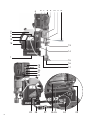 2
2
-
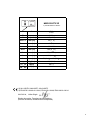 3
3
-
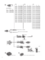 4
4
-
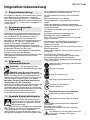 5
5
-
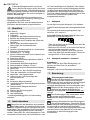 6
6
-
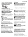 7
7
-
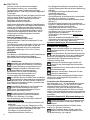 8
8
-
 9
9
-
 10
10
-
 11
11
-
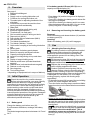 12
12
-
 13
13
-
 14
14
-
 15
15
-
 16
16
-
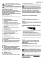 17
17
-
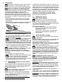 18
18
-
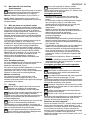 19
19
-
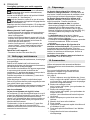 20
20
-
 21
21
-
 22
22
-
 23
23
-
 24
24
-
 25
25
-
 26
26
-
 27
27
-
 28
28
-
 29
29
-
 30
30
-
 31
31
-
 32
32
-
 33
33
-
 34
34
-
 35
35
-
 36
36
-
 37
37
-
 38
38
-
 39
39
-
 40
40
-
 41
41
-
 42
42
-
 43
43
-
 44
44
-
 45
45
-
 46
46
-
 47
47
-
 48
48
-
 49
49
-
 50
50
-
 51
51
-
 52
52
-
 53
53
-
 54
54
-
 55
55
-
 56
56
-
 57
57
-
 58
58
-
 59
59
-
 60
60
-
 61
61
-
 62
62
-
 63
63
-
 64
64
-
 65
65
-
 66
66
-
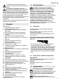 67
67
-
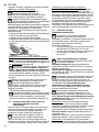 68
68
-
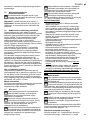 69
69
-
 70
70
-
 71
71
-
 72
72
-
 73
73
-
 74
74
-
 75
75
-
 76
76
-
 77
77
-
 78
78
-
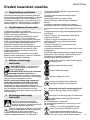 79
79
-
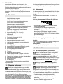 80
80
-
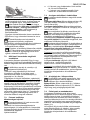 81
81
-
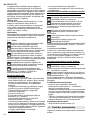 82
82
-
 83
83
-
 84
84
-
 85
85
-
 86
86
-
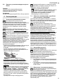 87
87
-
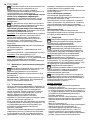 88
88
-
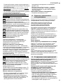 89
89
-
 90
90
-
 91
91
-
 92
92


Metabo MAG 28 LTX 32 Mode d'emploi
- Taper
- Mode d'emploi
- Ce manuel convient également à
dans d''autres langues
- italiano: Metabo MAG 28 LTX 32 Istruzioni per l'uso
- English: Metabo MAG 28 LTX 32 Operating instructions
- español: Metabo MAG 28 LTX 32 Instrucciones de operación
- Deutsch: Metabo MAG 28 LTX 32 Bedienungsanleitung
- русский: Metabo MAG 28 LTX 32 Инструкция по эксплуатации
- Nederlands: Metabo MAG 28 LTX 32 Handleiding
- português: Metabo MAG 28 LTX 32 Instruções de operação
- dansk: Metabo MAG 28 LTX 32 Betjeningsvejledning
- polski: Metabo MAG 28 LTX 32 Instrukcja obsługi
- svenska: Metabo MAG 28 LTX 32 Bruksanvisningar
- suomi: Metabo MAG 28 LTX 32 Käyttö ohjeet