
Limelight by Lutron OEM Integration Guide
Integration Guide
P/N 041664 Rev. D
01/2019
1 Customer Assistance: 1.844.LUTRON1
(1.844.588.7661)
This document is intended for luminaire/fixture manufacturers who are integrating Limelight by Lutron
LL-INTMOUNT and LL-PIR-L/M/H modules into their luminaires. It provides recommendations for electrical and
mechanical integration of these modules into a luminaire, and recommended manufacturing test procedures.
1. Standards
• RoHS Compliant
• FCC15.247 / IC RSS-247 (LL-INTMOUNT)
• cULus Recognized for internal mounting at a fixture OEM
• IP66 (wet locations) (LL-PIR-L/M/H) when lens assembly is installed correctly at fixture manufacturer
2. Model Numbers
Model Number Description
LL-INTMOUNT Limelight by Lutron Radio Module PCB Assembly
LL-PIR-L Limelight by Lutron PIR Sensor Assembly; for 8 to 15 ft (2.5 to 4.6 m) mounting height
LL-PIR-M Limelight by Lutron PIR Sensor Assembly; for 16 to 30 ft (4.9 to 9 m) mounting height
LL-PIR-H Limelight by Lutron PIR Sensor Assembly; for 31 to 40 ft (9.5 to 12 m) mounting height
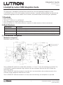
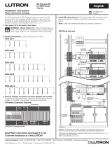
3. LL-INTMOUNT Integration
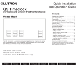
Mechanical Integration
Dimensions shown as: in (mm)
The LL-INTMOUNT module has multiple holes (diameter = 0.11 in [2.75 mm]) for mounting to a luminaire. The
LL-INTMOUNT should be mounted using a minimum of two of the holes to ensure that the PCB does not
excessively vibrate.
The LL-INTMOUNT should be mounted in a location that is not accessible by the user because parts of the
PCB have a high-voltage and should be out of reach.
The LL-INTMOUNT should be mounted as far away from metal housings and components as possible.
Top View
Bottom View
Tallest component
approx. 0.8 (20.3)
Tallest
component
approx. 0.16 (4)
2.69 (68.3)
1.12 (28.5)
1.12 (28.5)
1.12 (28.5)
1.12 (28.5)
1.24 (31.4)
0.57 (14.5)
0.19 (4.8)
0.57 (14.5)
0.57 (14.5)
0.24 (6.19)
0.24 (6.19)
0.57 (14.5)
0.829 (21)
Ø2.751
(Ø69.9)
Holes
Ø2.751 (Ø69.9)
Clearance areas
both sides of PCB
Ø0.23 (Ø5.84)
Solder mask is not relieved around
holes. If using metal fasteners,
plastic washers/spacers must
be used.
Preferred mounting hole
Preferred mounting hole

Limelight by Lutron OEM Integration Guide
2 Customer Assistance: 1.844.LUTRON1
(1.844.588.7661)
Electrical Integration
Warning: Shock Hazard! May result in serious injury or death. Disconnect power before servicing or
installing. This is a line voltage product and should only be installed / assembled into a fixture when power
is not applied.
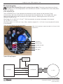
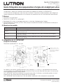
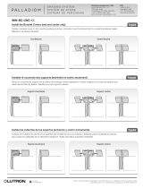
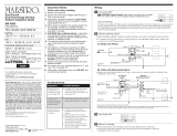
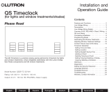
5-Pin Connector (J1)
The LL-INTMOUNT has a 5-pin connector for connection to the AC power and the luminaire. During
manufacturing, solid core or tinned wires can be pressed into the connector slots. For stranded wires, press
down on the button next to each connector slot to allow wire entry. Releasing the button will cause the
connector to grip the wire.
Wire Gauge: 16 – 20 AWG (1.5 – 0.5 mm
2
). The 5-pin connector can accept wire gauges in the range of
16 – 20 AWG (1.5 – 0.5 mm
2
).
Wire Strip Length: 0.3 – 0.35 in (8 – 9 mm). Wires should be stripped 0.3 – 0.35 in (8 – 9 mm) for optimal fit into the
5-pin connector.
The 5 pins are called out in the image below.
Continued on next page...
Line (black)
Neutral (white)
Switched Hot (red)
DIM+ (violet)
DIM- (grey)
LED Driver
LL-INTMOUNT
LL-PIR
Luminarie Power
Connection
Line/
Hot
Neutral
Switched Hot
DIM+
DIM-
Typical Wiring Diagram
Note: All wire retentions meet or exceed UL1059 and UL486
requirements

Limelight by Lutron OEM Integration Guide
3 Customer Assistance: 1.844.LUTRON1
(1.844.588.7661)
Electrical Integration (continued)
Power Connections
The LL-INTMOUNT can accept an input voltage range of 120 – 277 V~ (phase-to-phase possible).
The LL-INTMOUNT switches to the load the same voltage it is fed.
The Load output connection can support an electronic ballast load of up to 1000 W at 277 V~ and 600 W at
120 V~. Multiple loads can be driven by the same LL-INTMOUNT as long as the total wattage does not exceed
the maximum wattage for the given drive voltage.
OEM Validation Process
In order to ensure proper Lutron by Limelight system functions, all lighting fixtures that plan to integrate
LL-INTMOUNT into them need to be validated through Lutron. A picture or fixture design plan with the intended
install location called out should be provided to Lutron via [email protected]. Lutron may
request additional fixture information along with a sample fixture for further RF testing. If a sample is requested,
the required performance testing may take up to 3 weeks, starting from when the sample is received by Lutron.
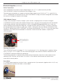
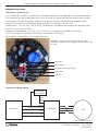
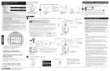
For best RF performance of the LL-INTMOUNT, the antenna should be kept 1.25 in (31.75 mm) from other metal
components and should not be concealed in a metal box. If either of these are violated a sample fixture
will be requested.
Dimming Connections
The LL-INTMOUNT outputs an analog 0.5 – 10 V- for dimming (0 – 10 V- dimming output, capable of sinking
up to 1.0 mA of 0 – 10 V- signal). The sum of the dimming input sink current for all drivers connected to the
LL-INTMOUNT should not exceed this requirement.
The dimming connection is separated from all other external connections (neutral, hot, load, external sensor
connector) with 100k ohms of resistance. This circuit is still an electric shock hazard and should not be
accessible in the end product.
Antenna location. Keep
metal components 1.25 in
(31.75 mm) away when
possible.
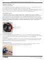
Strain Relief
It is strongly recommended to zip tie the 5 wires, coming from the 5-pin connector, together within 2 in (51 mm)
of the connector to provide strain relief as shown below.

Limelight by Lutron OEM Integration Guide
4 Customer Assistance: 1.844.LUTRON1
(1.844.588.7661)
Handling / ESD
Appropriate ESD protection should be taken when handling LL-INTMOUNT PCBs as the exposed PCB is
susceptible to ESD, which could damage the LL-INTMOUNT. The conformal coating on the PCB is meant to
protect it from moisture and is not intended as ESD protection.
Some safe places to hold the LL-INTMOUNT are the large blue varistor (lollipop), the relay, and the 5-pin
connector.
Surge Suppression
If the LL-INTMOUNT will be used in an environment that requires additional surge protection, such as outdoor
lighting, then it is up to the manufacturer of the luminaire to ensure that the additional surge protection is
provided. This is typically done with a separate surge protection device (SPD) rated for at least 10 kV.
Temperature / Humidity
The LL-INTMOUNT is designed to be installed inside a luminaire and therefore is designed to handle high
temperatures. The LL-INTMOUNT is designed and rated to operate in an ambient temperature of -40 – 176 ˚F
(-40 – 80 ˚C). Ambient air temperature is measured at least 1 in (25.5 mm) away from the LL-INTMOUNT.
The LL-INTMOUNT is not waterproof and should not be mounted in a location where it will receive direct contact
with water. It is, however, conformal coated and can withstand humid or moist conditions.
Regulatory Labelling Requirements
FCC
When integrating the LL-INTMOUNT into a product it must be ensured that the FCC labelling requirements are
met. This includes a clearly visible label on the outside of the finished product specifying the FCC identifier (FCC
ID: S4GEM35XB) as well as the FCC notice shown below. This exterior label can use wording such as “Contains
Transmitter Module FCC ID: S4GEM35XB” or “Contains FCC ID:S4GEM35XB” although any similar wording that
expresses the same meaning may be used. The label should also show the FCC Symbol as shown below.
FCC Notice: This device complies with Part 15 of the FCC rules. Operation is subject to the following two
conditions: (1) this device may not cause harmful interference, and (2) this device must accept any interference
received, including interference that may cause undesired operation.
FCC Symbol:
Industry Canada (IC-ID: 8735A-EM35XB)
The labelling requirements for Industry Canada are similar to those of the FCC. Again a clearly visibly label must
be placed on the outside of the finished product stating something like “Contains Transmitter Module,
IC: 8735A-EM35XB”, although any similar wording that expresses the same meaning may be used.

Limelight by Lutron OEM Integration Guide
5 Customer Assistance: 1.844.LUTRON1
(1.844.588.7661)
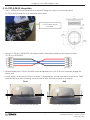
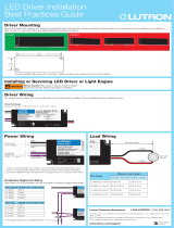
4. LL-PIR-(L/M/H) Integration
The LL-INTMOUNT can be connected to an external Limelight by Lutron Passive Infrared sensor
(LL-PIR-[L/M/H]) through the 4-pin connector shown below.
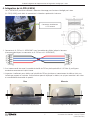
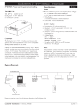
2. Recommended plastic PIR lens assembly should be tightened to 4 in-lbs (0.45 N•m) to properly engage the
internal seal.
3. Visually inspect to verify plastic PIR lens assembly is seated properly, and not tilted relative to the fixture. Tilting
could possibly imply cross-threading, which can lead to leaks and eventual failure of the product.
Good Bad
Consistent spacing around the perimeter Uneven spacing around the perimeter
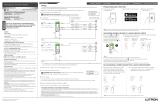
1. Connect LL-PIR to LL-INTMOUNT with cable assembly shown below (either end can connect to either
LL-PIR or LL-INTMOUNT).
Ø1.18
(Ø29.94)
Ø0.06
(Ø1.69)
Ø0.99
(Ø25.29)
1.08
(27.47)
1.5
(38.09)
LL-PIR External Sensor
Connector

Limelight by Lutron OEM Integration Guide
6 Customer Assistance: 1.844.LUTRON1
(1.844.588.7661)
5. Manufacturing Test
The LL-INTMOUNT has features which can aid in integrating Limelight by Lutron during manufacturing. These
features can be used to efficiently determine that the LL-INTMOUNT was correctly assembled into the luminaire
and can be incorporated into an automated manufacturing test process.
LL-INTMOUNT LED
The LL-INTMOUNT has a red LED on the bottom side of the PCB (opposite side from the connector). When
the LL-INTMOUNT is powered this LED should come on. The state of the LED will tell you information about the
state of the LL-INTMOUNT.
LL-INTMOUNT State: LED State Action Required:
Not functioning Not lit Need to check wiring
Waiting to join network Solid on Initial install: pre-commissioning
Joined to a network Blinking: 1 sec on, 1 sec off RF mesh is built; normal operation
Received message Blinking: 50 ms on, 50 ms off,
10 times
RF communication to/from the
gateway
Occupancy sensor detected Blinking: 200 ms on, 50 ms off,
40 times
LL-INTMOUNT and LL-PIR are
properly connected (at startup/reset
only – blinking will stop once it is
commissioned correctly)
Luminaire Power Up Timing
When the LL-INTMOUNT powers up, it cycles the luminaire through various states so the manufacturer can
determine if the luminaire has been wired up correctly. The power up sequence is as follows:
Low Off Low Medium High
1 second* For 1 second* For 3 seconds For 3 seconds Indefinitely
* This time may vary depending on the driver capacitance variability.
Power Up Failure Modes:
It is strongly recommended to zip tie the 5 wires, coming from the 5-pin connector, together within 2 in (51 mm)
of the connector to provide strain relief as shown on page 3.
1. Luminaire never turns off: The LL-INTMOUNT has been bypassed. The luminaire driver line input (black wire)
should be connected to LL-INTMOUNT switched hot terminal.
2. Luminaire never turns on:
a. Line wire of driver is not connected to LL-INTMOUNT switched hot terminal.
b. Hot (black) wire not connected to LL-INTMOUNT line terminal.
c. Neutral (white) wire not connected to luminaire neutral and LL-INTMOUNT neutral terminal.
3. Luminaire turns on and stays on high: Dim wires not connected or reversed. Double check dim wire connections.
6. Warranty
Limelight by Lutron products come with a 5 year, parts replacement warranty. If you need to request an RMA to
return parts contact Lutron Customer Assistance at www.lutron.com/support or 1.844.LUTRON1.

7
Lutron Electronics Co., Inc.
7200 Suter Road
Coopersburg, PA 18036-1299 U.S.A.
Limelight by Lutron OEM Integration Guide
)Lutron and Lutron are trademarks of Lutron Electronics Co., Inc., registered in the U.S. and other countries.
Limelight is a trademark of TwistHDM, LLC.
Lutron Contact Numbers
WORLD HEADQUARTERS
USA
Lutron Electronics Co., Inc.
7200 Suter Road
Coopersburg, PA 18036-1299
TEL: +1.610.282.3800
FAX: +1.610.282.1243
Customer Assistance: 1.844.
LUTRON1 (1.844.588.7661)
North & South America
Technical Hotlines
USA, Canada, Caribbean:
1.800.523.9466
Mexico:
+1.888.235.2910
Central/South America:
+1.610.282.6701
EUROPEAN HEADQUARTERS
United Kingdom
Lutron EA Ltd.
6 Sovereign Close
London, E1W 3JF United Kingdom
TEL: +44.(0)20.7702.0657
FAX: +44.(0)20.7480.6899
FREEPHONE (UK): 0800.282.107
Technical Support: +44.(0)20.7680.4481
ASIAN HEADQUARTERS
Singapore
Lutron GL Ltd.
15 Hoe Chiang Road
#07-03, Tower 15
Singapore 089316
TEL: +65.6220.4666
FAX: +65.6220.4333
Technical Support: 800.120.4491
lutronsea@lutron.com
Asia Technical Hotlines
Northern China: 10.800.712.1536
Southern China: 10.800.120.1536
Hong Kong: 800.901.849
Indonesia: 001.803.011.3994
Japan: +81.3.5575.8411
Macau: 0800.401
Taiwan: 00.801.137.737
Thailand: 001.800.120.665853
Other Countries: +65.6220.4666

Guide d’intégration des équipementiers d’origine de Limelight par Lutron
Guide d’intégration
N° de pièce 041664 Rév. C
01/2019
1 Assistance à la clientèle: 1.844.LUTRON1
(1.844.588.7661)
Ce document s’adresse aux fabricants de luminaires qui intègrent les modules LL-INTMOUNT et
LL-PIR-L/M/H de Limelight par Lutron dans leurs luminaires. Il fournit des recommandations pour intégrer ces
modules électrique et mécanique dans un luminaire et les procédures des tests de fabrication recommandés.
1. Normes
• Conforme à la norme RoHS
• FCC15.247 / IC RSS-247 (LL-INTMOUNT)
• Homologué cULus pour un montage interne dans un luminaire d’équipementier d’origine
• IP66 (emplacements humides) (LL-PIR-L/M/H) lorsque l’ensemble de la lentille est correctement installé par le
fabricant de luminaires
2. Numéros de modèle
Numéro de modèle Description
LL-INTMOUNT Ensemble de circuit imprimé du module radio de Limelight par Lutron
LL-PIR-L
Ensemble de détecteur PIR de Limelight par Lutron; pour une hauteur de montage de
2,5 à 4,6 m (8 à 15 pi)
LL-PIR-M
Ensemble de détecteur PIR de Limelight par Lutron; pour une hauteur de montage de
4,9 à 9 m (16 à 30 pi)
LL-PIR-H
Ensemble de détecteur PIR de Limelight par Lutron; pour une hauteur de montage de
9,5 à 12 m (31 à 40 pi)
3. Intégration de LL-INTMOUNT
Intégration mécanique
Dimensions représentées en : mm (po)
Le module LL-INTMOUNT présente plusieurs trous (diamètre = 2,75mm [0,11po] permettant de le monter
sur un luminaire. Le LL-INTMOUNT doit être monté en utilisant au moins deux des trous pour s’assurer que le
circuit imprimé ne vibre pas excessivement.
Le LL-INTMOUNT doit être installé dans un endroit inaccessible à l’utilisateur, car certaines parties du circuit
imprimé sont sous haute tension et doivent être hors de portée.
Le LL-INTMOUNT doit être monté aussi loin des boîtiers métalliques et des composants que possible.
Vue de dessus
Vue de dessous
Composant le plus
haut environ
20,3 (0,8)
Composant le
plus haut environ
4 (0,16)
68,3 (2,69)
28,5 (1,12)
28,5 (1,12)
28,5 (1,12)
28,5 (1,12)
31,4 (1,24)
14,5 (0,57)
4,8 (0,19)
14,5 (0,57)
14,5 (0,57)
6,19 (0,24)
6,19 (0,24)
14,5 (0,57)
21 (0,829)
Ø69,9
(Ø2,751)
Trous
Ø69,9 (Ø2,751)
Zones de
dégagement de
chaque côté du
circuit imprimé
Ø5,84 (Ø0,23)
L’épargne de soudage n’est pas
dégradée autour des trous. Si vous
utilisez des fixations métalliques, des
rondelles/entretoises en plastique
doivent être utilisées.
Trou de montage préférentiel
Trou de montage préférentiel

Guide d’intégration des équipementiers d’origine de Limelight par Lutron
2 Assistance à la clientèle: 1.844.LUTRON1
(1.844.588.7661)
Intégration électrique
Connecteur à 5 broches (J1)
Le LL-INTMOUNT dispose d’un connecteur à 5broches permettant de le connecter à l’alimentation électrique
et au luminaire. Lors de sa fabrication, des fils massifs ou des fils étamés peuvent être pressés dans les fentes
du connecteur. Pour les fils torsadés, appuyez sur le bouton à côté de chaque fente du connecteur pour
permettre l’entrée du fil. Le relâchement du bouton permet au connecteur de saisir le fil.
Diamètre de fil: 1,5 à 0,5mm
2
(16 à 20 AWG). Le connecteur à 5broches peut accepter des diamètres de fil
de 1,5 à 0,5mm
2
(16 à 20 AWG).
Longueur du câble dénudé : 8 à 9mm (0,3 à 0,35po). Les fils doivent être dénudés sur 8 à 9mm
(0,3 à 0,35po) pour un ajustement optimal dans le connecteur à 5broches.
Les 5 broches sont détaillées dans l’image ci-dessous.
Suite à la page suivante…
Pilote de DEL
LL-INTMOUNT
LL-PIR
Connexion de
l’alimentation
des luminaires
Ligne/
Sous
tension
Neutre
Conducteur commuté
DIM+
DIM-
Schéma de câblage typique
Remarque : Toutes les forces de rétention des câbles
respectent ou dépassent les exigences des normes UL1059
et UL486
Ligne (noir)
Neutre (blanc)
Conducteur commuté (rouge)
DIM+ (violet)
DIM- (gris)

Guide d’intégration des équipementiers d’origine de Limelight par Lutron
3 Assistance à la clientèle: 1.844.LUTRON1
(1.844.588.7661)
Intégration électrique (suite)
Connexions d’alimentation
Le LL-INTMOUNT peut accepter une plage de tension d’entrée de 120 à 277V~ (phase-to-phase possible).
Le LL-INTMOUNT commute à la charge la même tension que son alimentation.
La connexion de sortie de la charge peut supporter une charge de ballast électronique allant jusqu’à 1000W
à 277V~ et 600W à 120V~. Plusieurs charges peuvent être pilotées par le même LL-INTMOUNT tant que la
puissance totale ne dépasse pas la puissance maximale de la tension de pilotage donnée.
OEM Validation Process
In order to ensure proper Lutron by Limelight system functions, all lighting fixtures that plan to integrate
LL-INTMOUNT into them need to be validated through Lutron. A picture or fixture design plan with the intended
install location called out should be provided to Lutron via [email protected]. Lutron may
request additional fixture information along with a sample fixture for further RF testing. If a sample is requested,
the required performance testing may take up to 3 weeks, starting from when the sample is received by Lutron.
For best RF performance of the LL-INTMOUNT, the antenna should be kept 1.25 in (31.75 mm) from other metal
components and should not be concealed in a metal box. If either of these are violated a sample fixture
will be requested.
Connexions de gradation
Le LL-INTMOUNT produit une sortie analogique de 0,5 à 10V- pour la gradation (sortie de gradation de
0 à 10V-, capable de consommer jusqu’à 1,0mA du signal de 0 à 10 V-). La somme des courants sources
de l’entrée de gradation de tous les pilotes connectés au LL-INTMOUNT ne doit pas dépasser
cette exigence.
La connexion de gradation est séparée de toutes les autres connexions externes (neutre, conducteur, charge,
connecteur de capteur externe) avec une résistance de 100kohms. Ce circuit présente toujours un risque
d’électrocution et ne doit pas être accessible dans le produit final.
Réducteur de tension
Il est fortement recommandé d’attacher ensemble les 5fils sortant du connecteur à 5broches à moins de
51mm (2po) du connecteur pour réduire la tension comme représenté ci-dessous.
Antenna location. Keep
metal components 1.25 in
(31.75 mm) away when
possible.

Guide d’intégration des équipementiers d’origine de Limelight par Lutron
4 Assistance à la clientèle: 1.844.LUTRON1
(1.844.588.7661)
Manutention / ESD (DES)
Une protection appropriée contre les DES doit être mise en œuvre lors de la manipulation des circuits imprimés
des LL-INTMOUNT car les circuits imprimés exposés sont sensibles aux décharges électrostatiques, ce qui
pourrait endommager le LL-INTMOUNT. Le revêtement enrobant sur le circuit imprimé est destiné à le protéger
de l’humidité et ne doit pas servir de protection contre les DES.
Des endroits sûrs pour maintenir le LL-INTMOUNT sont la grande varistance bleue (sucette), le relais et le
connecteur à 5broches.
Suppression des surtensions
Si le LL-INTMOUNT est utilisé dans un environnement nécessitant une protection supplémentaire contre les
surtensions, tel qu’un éclairage extérieur, il appartient au fabricant de luminaires de s’assurer que la protection
supplémentaire contre les surtensions est fournie. Cela est généralement fait à l’aide d’un dispositif de
protection contre les surtensions distinct certifié pour au moins 10kV. Température / humidité
Le LL-INTMOUNT est conçu pour être installé à l’intérieur d’un luminaire et donc pour supporter des
températures élevées. Le LL-INTMOUNT a été conçu et évalué pour fonctionner à une température ambiante
de -40 à 80 ˚C (-40 à 176 ˚F). La température de l’air ambiant est mesurée à une distance d’au moins 25,5mm
(1po) du LL-INTMOUNT.
Le LL-INTMOUNT n’est pas étanche et ne doit pas être monté dans un endroit où il sera en contact direct avec
de l’eau. Toutefois, il possède un revêtement enrobant et peut résister à des conditions humides ou moites.
Exigences d’étiquetage réglementaires
FCC
Lors de l’intégration du LL-INTMOUNT dans un produit, on veillera à ce que l’étiquetage respecte les exigences
de la FCC. Ceci inclut une étiquette clairement visible sur l’extérieur du produit fini spécifiant l’identifiant FCC
(FCC ID: S4GEM35XB) ainsi que l’avis de la FCC représenté ci-dessous. Cette étiquette extérieure peut
utiliser des formules telles que «Contient un module émetteur FCC: S4GEM35XB» ou «Contient FCC ID:
S4GEM35XB» bien que n’importe quel autre libellé similaire ayant le même sens puisse être utilisé. L’étiquette
doit aussi montrer le symbole de la FCC, comme représenté ci-dessous.
Avis de la FCC: Cet appareil est conforme à la partie 15 des règles de la FCC. Le fonctionnement est sous
réserve des deux conditions suivantes: (1) cet appareil ne doit pas provoquer d’interférences nuisibles, et (2)
cet appareil ne doit accepter aucune interférence reçue, y compris des interférences qui pourraient provoquer
un fonctionnement indésirable.
Symbole FCC:
Industrie Canada (IC-ID: 8735A-EM35XB)
Les exigences d’étiquetage d’Industrie Canada sont semblables à celles de la FCC. À nouveau, une étiquette
clairement visible doit être placée à l’extérieur du produit fini indiquant une formule de type «Contient un module
émetteur, IC: 8735A-EM35XB», bien que n’importe quel libellé similaire ayant le même sens puisse être utilisé.

Guide d’intégration des équipementiers d’origine de Limelight par Lutron
5 Assistance à la clientèle: 1.844.LUTRON1
(1.844.588.7661)
4. Intégration du LL-PIR-(L/M/H)
Le LL-INTMOUNT peut être connecté à détecteur infrarouge passif externe Limelight par Lutron
(LL-PIR-[L/M/H]) par le biais du connecteur à 4broches représenté ci-dessous.
2. Il est recommandé de serrer l’ensemble de lentille du PIR en plastique lentille à 0,45N•m (4po-lb) pour
enclencher correctement le joint interne.
3. Inspectez visuellement pour vérifier que la lentille du PIR en plastique est correctement installée et n’est pas
inclinée par rapport au luminaire. Une inclinaison pourrait impliquer un défaut, ce qui peut conduire à des fuites
et une défaillance éventuelle du produit.
Bon Mauvais
Espacement uniforme autour du périmètre Espacement inégal autour du périmètre
1. Connectez le LL-PIR au LL-INTMOUNT avec l’ensemble des câbles indiqué ci-dessous
(chaque extrémité peut se connecter au LL-PIR ou au LL-INTMOUNT).
Ø29,94
(Ø1,18)
Ø1,69
(Ø0,06)
Ø25,29
(Ø0,99)
27,47
(1,08)
38,09
(1,5)
Connecteur de détecteur
LL-PIR externe

Guide d’intégration des équipementiers d’origine de Limelight par Lutron
6 Assistance à la clientèle: 1.844.LUTRON1
(1.844.588.7661)
5. Test de fabrication
Le LL-INTMOUNT possède des caractéristiques qui peuvent aider à intégrer Limelight par Lutron durant la
fabrication. Ces caractéristiques peuvent être utilisés pour déterminer efficacement que le LL-INTMOUNT a été
monté correctement dans le luminaire et peut être incorporé à un processus de test de fabrication automatisé.
DEL du LL-INTMOUNT
Le LL-INTMOUNT est équipé d’une DEL rouge sur le côté inférieur du circuit imprimé (du côté opposé au
connecteur). Lorsque le LL-INTMOUNT est alimenté, cette DEL s’allume. L’état de la DEL vous indiquera des
informations sur l’état du LL-INTMOUNT.
État du LL-INTMOUNT: État de la DEL Action requise:
Ne fonctionne pas Pas allumée Vérifiez le câblage
En attente de connexion à
un réseau
Allumée en continu Installation initiale : mise en service préalable
Connecté à un réseau Clignote: 1sec allumée, 1sec éteinte Maille RF réalisée; fonctionnement normal
Message reçu Clignote: 50ms allumée, 50ms
éteinte, 10fois
Communication RF de/vers la passerelle
Détecteur d’occupation détecté Clignote: 200ms allumée, 50ms
éteinte, 40fois
LL-INTMOUNT et LL-PIR sont correctement
connectés (au démarrage / à la réinitialisation
seulement - le clignotement s’arrête une
fois que la mise en service a été effectuée
correctement)
Délai de mise sous tension du luminaire
Lorsque le LL-INTMOUNT s’allume, il fait passer le luminaire par différents états pour permettre au fabricant de
déterminer si le luminaire a été câblé correctement. La séquence de démarrage est la suivante:
Bas Éteint Bas Moyen Haut
1 seconde* Pendant
1seconde*
Pendant
3secondes
Pendant
3secondes
Indéfiniment
* Cette durée peut varier selon la variabilité de la capacité du pilote.
Modes de défaillance de mise sous tension:
Il est fortement recommandé d’attacher ensemble les 5fils sortant du connecteur à 5broches à moins de
51mm (2po) du connecteur pour réduire la tension comme représenté à la page3.
1. Le luminaire ne s’éteint jamais: Le LL-INTMOUNT a été contourné. L’entrée de ligne du pilote du luminaire
(fil noir) doit être connectée à la borne conductrice commutée du LL-INTMOUNT.
2. Le luminaire ne s’allume jamais:
a. Le fil de ligne du pilote n’est pas connecté à la borne conductrice commutée du LL-INTMOUNT.
b. Le fil conducteur (noir) n’est pas connecté à la borne de ligne du LL-INTMOUNT.
c. Le fil neutre (blanc) n’est pas connecté au neutre du luminaire et à la borne neutre du LL-INTMOUNT.
3. Le luminaire s’allume et reste au seuil haut: Les fils de gradation ne sont pas connectés ou sont inversés.
Vérifiez à nouveau les connexions des fils de gradation.
6. Garantie
Les produits Limelight par Lutron sont fournis avec une garantie de remplacement des pièces de 5ans.
Si vous devez demander une autorisation de retour d’article pour retourner les pièces, contactez l’assistance
à la clientèle de Lutron sur www.lutron.com/support ou en appelant le 1.844.LUTRON1.

7
Lutron Electronics Co., Inc.
7200 Suter Road
Coopersburg, PA 18036-1299, É.-U.
Guide d’intégration des équipementiers d’origine de Limelight par Lutron
)Lutron et Lutron sont des marques commerciales de Lutron Electronics Co., Inc. enregistrées aux États-Unis et dans d’autres pays.
Limelight est une marque commerciale de TwistHDM, LLC.
Numéros de téléphone de Lutron
SIÈGE MONDIAL
États-Unis
Lutron Electronics Co., Inc.
7200 Suter Road
Coopersburg, PA 18036-1299
TÉL.: +1.610.282.3800
FAX: +1.610.282.1243
Assistance à la clientèle:
1.844.LUTRON1 (1.844.588.7661)
Lignes d’assistance technique,
Amérique du Nord et du Sud
États-Unis, Canada, Caraïbes:
1.800.523.9466
Mexique:
+1.888.235.2910
Amérique Centrale / du Sud:
+1.610.282.6701
SIÈGE EUROPÉEN
Royaume-Uni
Lutron EA Ltd.
6 Sovereign Close
London, E1W 3JF Royaume-Uni
TÉL.: +44.(0)20.7702.0657
FAX: +44.(0)20.7480.6899
Numéro gratuit(RU): 0800.282.107
Assistance technique:
+44.(0)20.7680.4481
SIÈGE POUR L’ASIE
Singapour
Lutron GL Ltd.
15 Hoe Chiang Road
#07-03, Tower 15
Singapour 089316
TÉL.: +65.6220.4666
FAX: +65.6220.4333
Assistance technique:
800.120.4491
lutronsea@lutron.com
Lignes d’assistance technique
pour l’Asie
Chine du Nord: 10.800.712.1536
Chine du Sud: 10.800.120.1536
Hong Kong: 800.901.849
Indonésie: 001.803.011.3994
Japon: +81.3.5575.8411
Macao: 0800.401
Taïwan: 00.801.137.737
Thaïlande: 001.800.120.665853
Autres pays: +65.6220.4666
-
 1
1
-
 2
2
-
 3
3
-
 4
4
-
 5
5
-
 6
6
-
 7
7
-
 8
8
-
 9
9
-
 10
10
-
 11
11
-
 12
12
-
 13
13
-
 14
14


Lutron Electronics LL-INTMOUNT Integration Manual
- Taper
- Integration Manual
dans d''autres langues
- English: Lutron Electronics LL-INTMOUNT
Documents connexes
-
 Lutron Electronics PALLADIOM WIN-BC-LWC Series Manuel utilisateur
-
 Lutron Electronics Maestro MRF2S-8SD010 Manuel utilisateur
-
 Lutron Electronics PDW-QS Series Guide d'installation
-
 Lutron Electronics Maestro MS-B202 Guide d'installation
-
 Lutron Electronics Vive Series Guide d'installation
-
 Lutron Electronics Hi-lume Premier 0.1 Installation Best Practices Manual
-
 Lutron Electronics GRAFIK Eye QS Quick Installation And Operation Manual
-
 Lutron Electronics QS Timeclock Quick Installation And Operation Manual
-
 Lutron Electronics QS Timeclock Mode d'emploi
-
 Lutron Electronics TVI-LMF-2A Install Manual


Autres documents
-
Lutron STCL-153M Guide d'installation
-
Lutron DVSTV-NHE Manuel utilisateur
-
512 AUDIO 512-LLT Mode d'emploi
-
-
Lutron IVALO Manuel utilisateur
-
SYNAPSE DIM10-281-21 Guide d'installation
-
Lutron PJ2-4B-TMN-S01 Manuel utilisateur
-