
Issue Date: January 18, 2017 Manual No: 0056-3260Revision: AG
SET-UP AND SAFE
OPERATING PROCEDURES
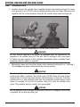
Cutting, Heating
and Welding Guide
English
OXY-FUEL
EQUIPMENT

ii
WE APPRECIATE YOUR BUSINESS!
Congratulations on your new Victor
®
product. We are proud to have you as our customer and
will strive to provide you with the best service and reliability in the industry. This product
is backed by our extensive warranty and world-wide service network. To locate your
nearest distributor or service agency, please contact a representative at the address and
phone number in your area listed on the back cover of this guide, or visit us on the web at
www.esab.com.
This Operating Manual has been designed to instruct you on the correct use and operation
of your Victor
®
product. Your satisfaction with this product and its safe operation is our
ultimate concern. Therefore, please take the time to read the entire manual, especially
the Safety Precautions. They will help you to avoid potential hazards that may exist
when working with this product.
YOU ARE IN GOOD COMPANY!
The Brand of Choice for Contractors and Fabricators Worldwide.
Victor
®
is a Global Brand of Gas Equipment Products for the ESAB Group, Inc. We
manufacture and supply to major welding industry sectors worldwide including;
Manufacturing, Construction, Mining, Automotive, Aerospace, Engineering, Rural and
DIY/Hobbyist.
We distinguish ourselves from our competition through market-leading, dependable
products that have stood the test of time. We pride ourselves on technical innovation,
competitive prices, excellent delivery, superior customer service and technical support,
together with excellence in sales and marketing expertise.
Above all, we are committed to develop technologically advanced products to achieve
a safer working environment within the welding industry.

iii
WARNING
Read and understand this entire Manual and your employer’s safety practices before
installing, operating, or servicing the equipment. While the information contained
in this Manual represents the Manufacturer’s judgment, the Manufacturer assumes
no liability for its use.
Cutting, Heating and Welding Guide
Set-up and Safe Operating Procedures
Instruction Guide Number 0056-3260
Published by:
The ESAB Group, Inc.
2800 Airport Rd.
Denton, TX. 76208
(940) 566-2000
www.esab.com
U.S. Customer Care: (800) 426-1888
International Customer Care: (940) 381-1212
Copyright © 2009, 2012 ESAB Group, Inc. All rights reserved.
Reproduction of this work, in whole or in part, without written permission of the publisher is
prohibited.
The publisher does not assume and hereby disclaims any liability to any party for any loss
or damage caused by any error or omission in this Manual, whether such error results from
negligence, accident, or any other cause.
Publication Date: September 1, 2009
Revision Date: June 1, 2016
Record the following information for Warranty purposes:
Where Purchased:
Purchase Date:
Equipment Serial #:

iv
Table of Contents
SECTION 1: INTRODUCTION ............................................................................... 1-1
1.01 How to Use this Manual ..............................................1-1
SECTION 2: SAFETY PRECAUTIONS .................................................................. 2-2
2.01 Housekeeping ..............................................................2-2
2.02 Protective Apparel .......................................................2-3
2.03 Fire Prevention ............................................................2-3
2.04 Cylinders .....................................................................2-4
SECTION 3: INDUSTRIAL GASES ....................................................................... 3-6
3.01 Oxygen ........................................................................3-6
3.02 Acetylene .....................................................................3-7
3.03 Natural Gas and Propane .............................................3-8
3.04 Propylene and Propylene-Based Fuel Gases ..............3-10
3.05 Fuel Gases with Natural Gas or Propane
Base Plus Liquid Hydrocarbon Additives ...................3-11
SECTION 4: OXY-FUEL APPARATUS ................................................................. 4-12
4.01 Oxygen and Fuel Supply ............................................ 4-12
4.02 Regulators .................................................................4-12
4.03 Torch Handle .............................................................4-15
4.04 Cutting Attachment ....................................................4-17
SECTION 5: SETTING UP EQUIPMENT FOR WELDING ...................................... 5-21
5.01 Cylinders ...................................................................5-21
5.02 Regulators .................................................................5-22
5.03 Gas Hoses .................................................................5-24
5.04 Torch Handle .............................................................5-24
5.05 Welding Nozzle .......................................................... 5-25
5.06 Setting Up To Weld, Lighting the Torch,
and Adjusting the Flame ............................................ 5-26
SECTION 6: WELDING PROCEDURES ............................................................... 6-29
6.01 Preparing the Metals to be Welded ...........................6-29
6.02 Preventing The Metals from Warping ....................... 6-29
6.03 Forehand and Backhand Welding Techniques ............6-30
6.04 Starting and Finishing the Weld .................................6-30
6.05 Oxy-Fuel Brazing and Braze Welding .........................6-32
SECTION 7: SETTING UP THE EQUIPMENT FOR CUTTING................................ 7-34
7.01 Setting up for Cutting Applications ............................7-34
SECTION 8: TROUBLESHOOTING ..................................................................... 8-41
SECTION 9: SPECIFICATIONS .......................................................................... 9-42
SECTION 10: GLOSSARY ............................................................................... 10-48
SECTION 11: STATEMENT OF WARRANTY ..................................................... 11-54

SET-UP AND SAFE OPERATING PROCEDURES
1-10056-3260
Introduction
SECTION 1:
INTRODUCTION
1.01 HOW TO USE THIS MANUAL
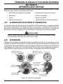
This guide contains important information related to the safe and efficient operation of oxy-fuel
welding, cutting, and heating apparatus.
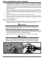
There are several potential hazards present when using oxy-fuel equipment. It is, therefore, necessary
that proper safety and operating procedures are understood prior to using such apparatus.
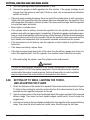
READ THIS BOOKLET THOROUGHLY AND CAREFULLY BEFORE ATTEMPTING TO OPERATE
OXY-FUEL WELDING, CUTTING, AND HEATING APPARATUS. A thorough understanding of the
proper safety and operating procedures will help to minimize the potential hazards involved, and
add to the efficiency and productivity of your work.
Welding, cutting, and heating operations should conform to applicable Federal, State, County or City
regulations for installation, operation, ventilation, fire prevention, and protection of personnel.
Detailed safety and operating instructions can be located within the ANSI Standard Z49.1, “Safety
in Welding and Cutting”, available from the American Welding Society, P.O. Box 351040, Miami,
FL. 33135 or www.aws.org. Other publications containing safety and operating instructions
are available from the following organizations: American Welding Society, (AWS) www.aws.org,
Occupational Safety and Health organization (OSHA) www.osha.gov, Compressed Gas Association
(CGA) www.cganet.com and National Fire Protection Agency (NFPA) www.nfpa.org.
Do Not attempt to use the apparatus unless you are trained in its proper use, or are under competent
supervision. Remember, the safest equipment, if incorrectly operated, may result in a mishap.
A system of notes, cautions and warnings emphasize important safety and operating information
in this booklet. These are as follows:
NOTE
NOTE conveys installation, operation, or maintenance information which is important
but not hazard-related.
CAUTION
CAUTION indicates a potentially hazardous situation which, if not avoided, may
result in injury.
WARNING
WARNING indicates a potentially hazardous situation which, if not avoided, could
result in death or serious injury.

2-2
CUTTING, HEATING AND WELDING GUIDE
0056-3260
Safety Precautions
SECTION 2:
SAFETY PRECAUTIONS
Be sure to read and understand all safety and operating instructions provided before using this
apparatus. RETAIN THESE INSTRUCTIONS IN A READILY AVAILABLE LOCATION FOR FUTURE
REFERENCE.
The following preliminary safety checklist is the basis for further specific safety information noted
throughout this booklet.
WARNING
This product contains chemicals, including lead, or otherwise produces chemicals known
to the State of California to cause birth defects and other reproductive harm. Wash
hands after handling.
WARNING
DO NOT attempt to use this apparatus unless you are trained in its proper use or are under
competent supervision. For your safety, practice the safety and operating procedures
described in this guide every time you use the apparatus. Deviating from these procedures
may result in fire, explosion, property damage and/or operator injury.
If, at any time, the apparatus you are using does not perform in the usual manner, or
you have difficulty in the use of the apparatus, shut the system off and STOP using it
immediately. DO NOT use the apparatus until the problem has been corrected.
WARNING
Service or repair of apparatus should be performed by a qualified repair technician
only. Improper service, repair, or modification of the product could result in damage
to the product or injury to the operator.
NOTE
The term “Qualified Repair Technician” refers to repair personnel capable of servicing
apparatus in strict accordance with all applicable Victor “Parts & Service Bulletins”
and literature.
2.01 HOUSEKEEPING
1. The work area must have a fireproof floor.
2. Work benches or tables used during welding, cutting, and heating operations must have
fireproof tops.
3. Use heat resistant shields or other approved material to protect nearby surfaces from
sparks and hot metal.
4. Move all combustible material away from the work area.

SET-UP AND SAFE OPERATING PROCEDURES
2-30056-3260
Safety Precautions
5. Ventilate welding, cutting, and heating work areas adequately to prevent accumulation
of explosive or toxic concentrations of gases. When working with lead, lead bearing
materials, steel coated with lead paints, cadmium-coated materials or any objects
containing metals that may generate or give off toxic fumes, always ensure that suitable
respiratory protection equipment is utilized.
6. When welding, be sure to read and understand the Material Safety Data Sheet (MSDS)
for the alloy being used.
7. Place the oxygen and fuel cylinders close to the location to where you are working.
Ensure the cylinders are at a safe distance from sparks or hot metal. Individually chain
or otherwise secure the cylinders to a wall, bench, post, cylinder cart, etc. to keep the
cylinders upright, and secure them from falling over.
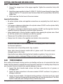
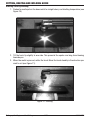
2.02 PROTECTIVE APPAREL
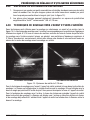
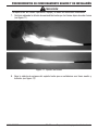
1. Protect yourself from sparks, flying slag, and flame brilliance at all times. Gas flames
produce infrared radiation that may have a harmful effect on the skin and especially
on the eyes. Select the appropriate goggles or mask with tempered lenses shaded 5 or
darker to protect your eyes from injury and provide good visibility of the work.
2. Always wear appropriate protective gloves and flame resistant clothing to protect skin
and clothing from sparks and slag. Keep collars, sleeves, and pockets buttoned. DO
NOT roll up sleeves or cuff pants.
3. Remove all flammable and readily combustible materials from your pockets, such as
matches and cigarette lighters.
4. Keep all clothing and protective apparel completely free of oil or grease.
5. Do not wear clothing that is easily ignited, such as polyester pants or shirts.
2.03 FIRE PREVENTION
Welding, cutting, and heating operations use fire or combustion as a basic tool. The process is
very useful when properly controlled. However, it can be extremely destructive if not performed
correctly in the proper environment.
Practice fire prevention techniques whenever oxy-fuel operations are in progress. A few simple
precautions can prevent most fires and help minimize damage in the event a fire does occur.
1. Keep ALL apparatus clean and free of grease, oil, and other flammable substances.
Inspect oxy-fuel apparatus for oil, grease, or damaged parts. DO NOT use the oxy-fuel
apparatus if oil or grease are present, or if damage is evident.
2. Never use oil, grease, or lubricant on or around any oxy-fuel apparatus. Even a trace of
oil or grease can ignite and burn violently in the presence of oxygen.
3. Keep flames, heat, and sparks away from cylinders, regulators, and hoses.
4. Flying sparks can travel up to a distance of 35 feet (10m) or more. Remove all combustible
materials away from areas where oxy-fuel operations are being performed.

2-4
CUTTING, HEATING AND WELDING GUIDE
0056-3260
Safety Precautions
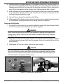
5. Operators may not become aware of a fire starting while operating apparatus. Their
vision is seriously hampered by the welding goggles and dark lenses. Depending upon
the circumstances of the work location, it may be advisable to have a fire watcher to
operate an extinguisher and sound a fire alarm in case of a fire.
6. Keep an approved fire extinguisher of the proper size and type in the work area. Inspect it
regularly to ensure that it is in proper working order. Know how to use the fire extinguisher.
7. Use heat resistant shields or other approved material to protect nearby surfaces, ceilings
and equipment from sparks and hot metal.
8. Only use oxy-fuel equipment with the fuel gas it was designed for.
9. After the equipment has been properly set up, open the acetylene cylinder valve
approximately 3/4 of a turn, but NO MORE than 1-1/2 turns. Keep the cylinder wrench,
if one is required, on the cylinder valve so the cylinder may be turned off quickly if it
becomes necessary.
10. All gases except acetylene: Open the fuel gas cylinder valve completely to seal the
cylinder back seal packing.
11. Never test for gas leaks with a flame. Use an approved leak-detector solution.
12. Never perform welding, cutting, and heating operations on a container that has held
toxic or combustible liquids or vapors.
13. Never perform welding, cutting, and heating operations in an area containing combustible
vapors, flammable liquids, or explosive dust.
14. Never perform welding, cutting, and heating operations on a closed container or vessel,
which may explode when heated.
15. Avoid operating the equipment in rooms with sprinkler systems unless there is sufficient
ventilation to keep the area cool.
16. When the work is complete, inspect the area for possible fires or smoldering materials.
2.04 CYLINDERS
All Government and insurance regulations relating to the storage of oxygen, acetylene and LPG
cylinders should be closely observed.
Industrial gas cylinders are made to rigid specifications and are inspected each time they are
refilled by your supplier. They are safe if properly handled.
For additional information on the safe handling of gas cylinders, contact your gas supplier or
refer to the Compressed Gas Association publication P-1, “Safe Handling of Compressed Gases
in Containers”.
• Keep all cylinders, empty or full, away from radiators, furnaces and other sources of heat.
• Avoid contact with electrical circuits.
• Keep oil and grease away from cylinders.
• Cylinders should be screened against direct rays from the sun.
• Protect cylinder valves from bumps and falling objects.

SET-UP AND SAFE OPERATING PROCEDURES
2-50056-3260
Safety Precautions
• Inspect the cylinder valves for damaged parts. Keep the valves clean, free from oil, grease,
and all foreign materials.
• Close cylinder valves when not in use, when empty, or when moving cylinders.
• Always be sure the cylinder valve is tightly closed before removing the regulators.
• Always replace the cylinder valve cap, if applicable, when the cylinder is not in use.
• Never allow anyone to strike an arc or tap an electrode against any cylinder.
• Never try to fill a cylinder or mix gases in a cylinder. Never draw gas from cylinders except
through properly attached pressure regulators or equipment designed for the purpose. If
damaged, send the regulator to the supplier or qualified repair technician for repairs. Do
not tamper with or alter cylinder numbers or markings.
• Never use cylinders as supports or rollers.
• When transporting cylinders with a crane, use an approved cylinder cradle only. Never use
a “magnet” crane to move cylinders
• Never lift the cylinder by its protective cap.
• If you are unable to make a gas-tight seal between the cylinder valve and a regulator nipple,
check to see if the connection nut is tight. If so, check the regulator inlet connection for
damage. If the cylinder valve is damaged, remove the cylinder from service and notify the
gas supplier.
• Never insert washers of lead or other material between the regulator and cylinder valve.
Never use oil or grease on the connections.
• Never use compressed gas cylinders without a pressure reducing regulator attached to
the cylinder valve.
• Never drag cylinders or roll them on the bottom edge, use a suitable cylinder cart.
• Never transport gas cylinders inside a passenger vehicle. Only transport gas cylinders in
a suitable ventilated service vehicle. See CGA PS-7, “CGA Position statement on the Safe
Transportation of Cylinders in Passenger Vehicles”.
• Use only standard cylinder keys to open cylinder valves, never extend the length of these
keys under any circumstances. If valves cannot be opened by hand, do not use a hammer
or a wrench; notify the supplier.
• Leave the cylinder key in position when fuel gas cylinder valves are open.
• Some cylinder valves, most notably acetylene cylinder valves, may require adjustment of
the valve packing. Consult your gas supplier for the proper method of adjusting the packing.
DO NOT use the cylinder if the packing is leaking.
WARNING
Cylinders are highly pressurized. Handle with care. Serious accidents can result
from improper handling or misuse of compressed gas cylinders. DO NOT drop the
cylinder, knock it over, expose it to excessive heat, flames or sparks. DO NOT strike
a cylinder in any manner.

3-6
CUTTING, HEATING AND WELDING GUIDE
0056-3260
Industrial Gases
SECTION 3:
INDUSTRIAL GASES
CAUTION
Fuel Gases may be toxic. Contact your gas supplier for the appropriate Material Safety
Data Sheet (MSDS) for each gas you use. The Hazardous Materials Regulations of
the Department of Transportation (DOT) regulates the transportation of industrial
gases and the cylinders used to transport them. Disposal of fuel gases may also be
controlled. Contact your local or state Department of Labor for further information.
3.01 OXYGEN
Gaseous chemical element, symbol: “O”; it is of great interest because it is the essential element
in the respiratory processes of most living cells and in combustion processes. It is the most
abundant element in the Earth’s crust. Nearly one fifth (in volume) of the air is oxygen. Oxygen
can be separated from air by fractionated liquefaction and distillation. One of the main applications
for oxygen is melting, and the refining and manufacturing of steel and other metals. Oxygen is
required to support any burning process. It is, therefore, combined with a “fuel” gas to produce
the desired operating flame. Oxygen itself is not flammable. However, the presence of pure
oxygen will dramatically accelerate the burning process. Oxygen can easily turn a small spark
into a roaring flame or explosion.
WARNING
Never allow oxygen to contact grease, oil, or other flammable substances. Although
oxygen by itself will not burn, these substances become highly explosive and may ignite
and burn rapidly when supported by pure oxygen. Oil or grease combined with oxygen
may ignite or even explode without the presence of excessive heat or flame.
Oxygen is ordinarily supplied in standard drawn steel cylinders. The 244 ft³ (7 m³) cylinder is the
most commonly used. Smaller and larger sizes are available. Full oxygen cylinders are normally
pressurized in excess of 2000 psi (900 Kg/cm²). Determine oxygen cylinder contents by reading
the inlet pressure gauge on the regulator when in use. For example, half the full cylinder pressure
rating indicates half the volume (ft³ / m³) of oxygen remaining. The maximum fill pressure should
always be stamped on the cylinder.
Due to the high pressure under which oxygen is contained, cylinders must always be handled
with great care. THE POTENTIALLY VIOLENT REACTION OF OIL, GREASE, OR ALL OTHER
CONTAMINANTS IN THE PRESENCE OF OXYGEN CANNOT BE OVERSTRESSED. SERIOUS INJURY
OR DEATH MAY EASILY RESULT IF OXYGEN IS USED AS A SUBSTITUTE FOR COMPRESSED
AIR. Oxygen should never be referred to as “air”.
WARNING
Never use oxygen: in pneumatic tools; in oil pre-heating burners; to start internal
combustion engines, to blow out pipelines; to dust off clothing or work area; to create
pressure; for ventilation. In short, under no circumstances use oxygen as a substitute
for compressed air or other gases. Use oxygen only for appropriate oxy-fuel cutting,
heating and welding applications.

SET-UP AND SAFE OPERATING PROCEDURES
3-70056-3260
Industrial Gases
OXYGEN VALVE OUTLET AND REGULATOR INLET CONNECTIONS:
CGA 540 up to 3000 PSIG (3700 - 20700 kPa); CGA 577 up to 4000 PSIG (4000 - 28000 kPa);
CGA 701 up to 5500 PSIG (4800 - 38000 kPa)
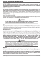
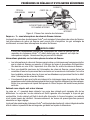
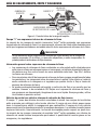
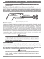
3.02 ACETYLENE
Acetylene is a compound of carbon and hydrogen (C
2
H
2
). It is a versatile industrial fuel gas used
in cutting, heating, welding, brazing, soldering, flame hardening, metallizing, and stress relieving
applications. It is produced when calcium carbide is submerged in water or from petrochemical
processes. The acetylene gas produced is then compressed into cylinders or fed into piping
systems. Acetylene becomes unstable when compressed in its gaseous state above 15 PSIG
(103 kPa). Therefore, it cannot be stored in a “hollow” cylinder under high pressure the way
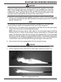
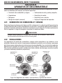
oxygen, for example, is stored. Acetylene cylinders are filled with a porous material (calcium-
silicate) creating, in effect, a “solid” as opposed to a “hollow” cylinder. The porous filling is then
saturated with liquid acetone. When acetylene is pumped into the cylinder, it is absorbed by the
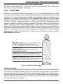
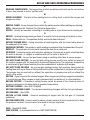
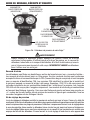
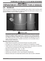
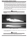
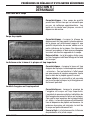
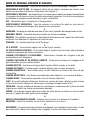
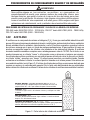
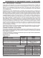
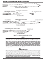
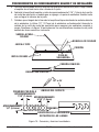
liquid acetone throughout the porous filling. It is held in a stable condition (see Figure 2). Filling
acetylene cylinders is a delicate process requiring special equipment and training. Acetylene
cylinders must, therefore, be refilled only by authorized gas distributors. Acetylene cylinders
MUST NEVER be transfilled.
POROUS FILLER:
(calcium-sicilate) 8% - 10%
The filler, which completely occupies the steel shell, is
90% - 92% composed of millions of interconnected pores.
ACETONE:
42%
Acetone is equal to 42% of the internal volume, and is
dispersed throughout the filler.
ACETYLENE GAS:
36%
The acetylene gas is uniformly absorbed by the acetone.
The resulting mixture occupies 78% of the internal volume.
RESERVE VOLUME AT 70˚ F:
10% - 12%
Since acetone and acetylene gas will expand as temperature
rises, a safety reserve must be present even at 150˚ F.
dwg-00377
Figure 2: Acetylene Cylinder Interior
Acetylene Cylinders
All acetylene cylinders are fitted with fusible plugs. These are designed to vent the cylinder contents
in the event of an unsafe condition arising in the cylinder that could be due to any number of
reasons, such as overheating from either incorrect operating techniques, faulty equipment, or in
conjunction with excessive temperature. In the event of a cylinder safety device malfunctioning,
remove the cylinder from service, place the cylinder in a well ventilated area, preferably outdoors,
and notify the supplier immediately.

3-8
CUTTING, HEATING AND WELDING GUIDE
0056-3260
Industrial Gases
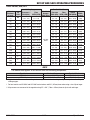
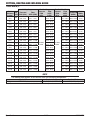
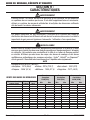
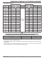
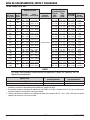
Commonly Available Acetylene Cylinder Capacities
Cubic Feet / ft³ (Cubic Meters / m³)
10 (0.3) 130 (3.7) 330 (9.3)
40 (1.1) 190 (5.4) 360 (10.2)
60 (1.7) 225 (6.4) 390 (11.0)
75 (2.1) 290 (8.2) 850 (24.1)
100 (2.8) 300 (8.5)
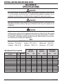
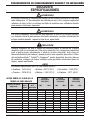
Acetylene cylinders used in the U.S.A. must conform to DOT 8 and 8 AL specifications.
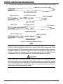
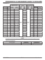
Specifications
SAFETY
Shock sensitivity
Unstable over 15 PSIG (103 kPa)
outside of cylinder
Explosive limits in oxygen (%) 3.0-93
Explosive limits in air (%) 2.5-80
Maximum allowable use pressure 15 PSIG (103 kPa)
Tendency to backfire Considerable
Toxicity Low
Maximum Withdrawal Rate 1/7 of cylinder contents per hour
COMBUSTION PROPERTIES
Neutral flame temperature in °F (°C) 5720 (3160)
Burning velocity in oxygen in ft./sec. (m/sec) 22.7 (6.9)
Primary flame in BTU/ft³ (MJ/m³) 507 (18.9)
Secondary flame in BTU/ft³ (MJ/m³) 963 (35.9)
Total heat in BTU/ft³ (MJ/m³) 1470 (54.8)
Total heating value in BTU/lb. (kJ/kg) 21600 (50140)
Auto ignition temperature in °F (°C) 763 - 824 (406 - 440)
VALVE OUTLET AND REGULATOR INLET CONNECTIONS
• Standard connection CGA 510
• Alternate standard connection CGA 300
• Small valve series (10 ft³ (0.3 m³) cylinder) CGA 200
• Small valve series (40 ft³ (1.1 m³) cylinder) CGA 520
*All values are approximations*
If more detailed specifications are required, contact your fuel gas supplier for the specific
properties of the fuel gas.
3.03 NATURAL GAS AND PROPANE
Natural gas is available throughout most areas of the U.S.A. and Canada. Physical properties vary
according to the geographical location. Methane is a colorless, odorless gas and is the principal
component of natural gas, a mixture containing about 75% methane (CH
4
), 15% ethane (C
2
H
6
),
and 5% other hydrocarbons, such as propane (C
3
H
8
) and butane (C
4
H
10
).
Propane (C
3
H
8
) is a non-renewable fossil fuel, like the natural gas and oil it is produced from. It
is known in popular terms as LPG (Liquefied Petroleum Gas). Similar to natural gas (methane),

SET-UP AND SAFE OPERATING PROCEDURES
3-90056-3260
Industrial Gases
propane is colorless and odorless. Although propane is nontoxic and odorless, foul-smelling
mercaptan is added to it to make gas leaks easy to detect.
Liquid Petroleum (LP) gases were discovered in 1912 when an American scientist, Dr. Walter
Snelling, discovered that these gases could be changed into liquids and stored under moderate
pressure. The LP-gas industry got its start shortly before World War I when a problem in the natural
gas distribution process popped up. A section of the pipeline in one natural gas field ran under a
cold stream, and the coldness led to a lot of liquids building up in the pipeline, sometimes to the
point of blocking the entire pipeline. Soon, engineers figured out a solution: facilities were built
to cool and compress natural gas, and to separate the gases that could be turned into liquids
(including propane and butane).
Both natural gas and propane are used as industrial fuel gases for flame cutting, scarfing, heating,
flame hardening, stress relieving, brazing, and soldering.
NATURAL GAS AND PROPANE CYLINDERS
Natural gas is transported by pipeline to most installations that use natural gas as a fuel gas.
Natural gas / Methane is authorized for shipment in a non-liquefied compressed gas cylinder
under DOT regulations.
Propane is available in on-site bulk storage tanks. It is also obtainable in 5-420 lb. (2-190 Kg) cylinders.
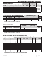
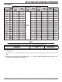
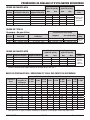
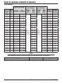
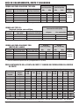
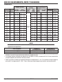
Specifications
SAFETY Natural Gas Propane
Shock sensitivity Stable Stable
Explosive limits in oxygen (%) 5.0-59 2.4-57
Explosive limits in air (%) 5.0-15 2.1-9.5
Maximum allowable use pressure Varies
Cylinder 120 PSIG @ 70°F
(800 kPa @ 21°C)
Tendency to backfire Slight Slight
Toxicity Low Low
COMBUSTION PROPERTIES Natural Gas Propane
Neutral flame temperature in °F (°C) 4600 (2538) 4579 (2526
Burning velocity in oxygen in ft./sec. (m/sec) 15.2 (4.6) 12.2 (3.7)
Primary flame in BTU/ft³ (MJ/m³) 55 (2.0) 295 (11.0)
Secondary flame in BTU/ft³ (MJ/m³) 995 (37.1) 2268 (84.5)
Total heat in BTU/ft³ (MJ/m³) 1050 (39.1) 2563 (95.5)
Total heating value in BTU/lb. (kJ/kg) 24800 (57660) 21600 (50140)
Auto ignition temperature in °F (°C) 999 (537) 874 (468)
VALVE OUTLET AND REGULATOR INLET CONNECTION
Natural Gas By Pipeline
Methane CGA 350
Methane (5500 PSIG (38000 kPa) Max.) CGA 695
Propane CGA 510
*All values are approximations*
If more detailed specifications are required, contact your fuel gas supplier for the specific
properties of the fuel gas.

3-10
CUTTING, HEATING AND WELDING GUIDE
0056-3260
Industrial Gases
3.04 PROPYLENE AND PROPYLENE-BASED FUEL GASES
Propylene, also known by its IUPAC name propene, is an organic compound having the chemical
formula C
3
H
6
. It is the second simplest member of the alkene class of hydrocarbons, ethylene
(ethene) being the simplest. At room temperature and pressure, propylene is a gas. It is colorless,
highly flammable, and has an odor similar to garlic.
Propylene is found in coal gas and can be synthesized by cracking petroleum.
In newer designs, cracking takes place using a very active zeolite-based catalyst in a short-contact
time vertical or upward sloped pipe called the “riser”. Pre-heated feed is sprayed into the base
of the riser via feed nozzles where it contacts extremely hot fluidized catalyst at 1230 to 1400°F
(665 to 760°C). The hot catalyst vaporizes the feed and catalyzes the cracking reactions that
break down the high molecular weight oil into lighter components, including LPG, gasoline, and
diesel. The catalyst-hydrocarbon mixture flows upward through the riser for just a few seconds
and then the mixture is separated via cyclones. The catalyst-free hydrocarbons are routed to a
main fractionator for separation into fuel gas, LPG, gasoline, light cycle oils used in diesel and
jet fuel, and heavy fuel oil.
These gases are industrial fuel gases used for flame cutting, scarfing, heating, flame hardening,
stress relieving, brazing and soldering. They may also be used in certain applications for welding
cast iron and aluminum.
Propylene and Propylene-Based Fuel Gas Cylinders
Available in on-site bulk storage tanks. Also available in portable 30 lb. (13.6 Kg) cylinders, and
larger 60-70 lb. (27.2-31.8 Kg) and 100-110 lb. (45.4 - 49.9 Kg) cylinders.
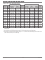
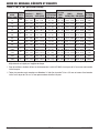
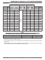
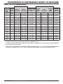
Specifications
SAFETY
Shock sensitivity Stable
Explosive limits in oxygen (%) 2.0-57
Explosive limits in air (%) 2.0-10
Maximum allowable use pressure
Cylinder 135 PSIG @ 70°F
(930 kPa @ 21°C)
Tendency to backfire Moderate
Toxicity Low
COMBUSTION PROPERTIES
Neutral flame temperature in °F (°C) 5240 (2893)
Burning velocity in oxygen in ft./sec. (m/sec) 15.0 (4.6)
Primary flame in BTU/ft³ (MJ/m³) 403 (15.0)
Secondary flame in BTU/ft³ (MJ/m³) 1969 (73.4)
Total heat in BTU/ft³ (MJ/m³) 2372 (88.4)
Total heating value in BTU/lb. (kJ/kg) 20000 (46400)
Auto ignition temperature in °F (°C) 896 (480)
VALVE OUTLET AND REGULATOR INLET CONNECTION
• CGA 510 - 0.885 in (22.5 mm) - 14 NGO-LH-INT (POL Outlet)
*All values are approximations*
If more detailed specifications are required, contact your fuel gas supplier for the specific
properties of the fuel gas.

SET-UP AND SAFE OPERATING PROCEDURES
3-110056-3260
Industrial Gases
3.05 FUEL GASES WITH NATURAL GAS OR PROPANE BASE
PLUS LIQUID HYDROCARBON ADDITIVES
These fuel gases consist of a natural gas or propane base which is enriched by a liquid hydrocarbon
additive. The liquid hydrocarbon additive is usually a low-boiling point, petroleum ether fraction
of n-pentane and / or iso-pentane. N-pentane has a heating value of approximately 4249 BTU/ft³
(158 MJ/m³). Pentane added to natural gas will show a greater percentage increase in heating
value, as the BTU heat value of natural gas is approximately 1050 BTU/ft³ (34.1 MJ/m³) This is
not meant to imply that all the fuel gases listed above use n-pentane or iso-pentane as the liquid
hydrocarbon additive.
The physical and combustion properties of these fuel gases vary according to the percentage of
additives added to the base of natural gas or propane. Use the general specifications for natural
gas and propane as listed in the preceding pages as a guide only. Contact your fuel gas supplier
for the specific properties of the fuel gas if more detailed specifications are required.

4-12
CUTTING, HEATING AND WELDING GUIDE
0056-3260
Oxy-Fuel Apparatus
SECTION 4:
OXY-FUEL APPARATUS
Typical oxy-fuel workstations normally include the following items, each designed to perform a
specific function:
• Oxygen and fuel supply • Cutting attachment and tip(s)
• Regulators • Welding nozzle(s)
• Hose • Heating nozzle(s)
• Torch Handle • Operator safety equipment
4.01 OXYGEN AND FUEL SUPPLY
There are two types of workstations, portable and stationary. The portable station is usually supplied
by cylinders mounted on a cart. The stationary units are supplied by piping or manifold systems.
The stationary system restricts the operator to the length of hose attached to the torch handle.
CAUTION
Always be aware of the gases in use at the station. Use only the type of apparatus
designed for use with those gases.
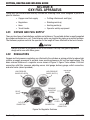
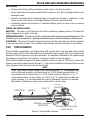
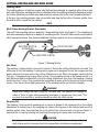
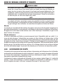
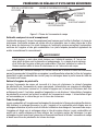
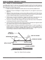
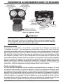
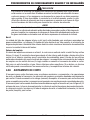
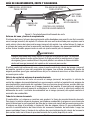
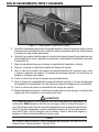
4.02 REGULATORS
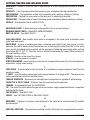
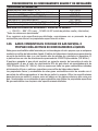
Oxygen and fuel pressure regulators are attached to the cylinders or piping outlets to reduce high
cylinder or supply pressures to suitable lower working pressures for oxy-fuel applications. The
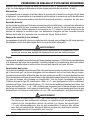
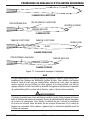
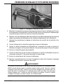
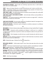
basic external features of a regulator are as shown in Figure 3. Figure 3 also shows: CGA inlet
connection with filter, pressure adjusting screw, inlet gauge, delivery gauge, outlet connection,
and relief valve (where provided).
LOW PRESSURE
GAUGE (DELIVERY)
HIGH PRESSURE
GAUGE (SUPPLY)
PRESSURE
GAUGE
PRESSURE
ADJUSTING
SCREW
OUTLET
CONNECTION
RELIEF
VALVE
INLET
CONNECTION
INLET
FILTER
OUTLET
CONNECTION
Figure 3a: Regulator Features

SET-UP AND SAFE OPERATING PROCEDURES
4-130056-3260
Oxy-Fuel Apparatus
LOW PRESSURE
GAUGE (DELIVERY)
HIGH PRESSURE
GAUGE (SUPPLY)
PRESSURE
ADJUSTING KNOB
OUTLET
CONNECTION
RELIEF
VALVE
INLET
CONNECTION
INLET
FILTER
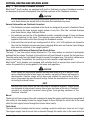
Figure 3b: Edge
™
Regulator Features
WARNING
Always keep the regulator free of oil, grease and other flammable substances.
Never use oil or grease on the regulator, cylinder or manifold connection. Only use
the regulator for the gas and pressure for which it was designed. NEVER alter a
regulator for use with any other gas.
Inlet Connection
Regulators are attached to the cylinders or piping outlets by their “inlet connections.” Inlet
connections must have a clean filter. All inlet connections conform to specifications and standards
set by the Compressed Gas Association (CGA) and are marked with an identifying CGA number.
CGA numbers identify the cylinder valve and gas service for which that inlet connection is
designed. Examples: CGA 510 has been designated for standard fuel gas cylinder connections
such as acetylene, propylene/propylene-based fuel gases and propane. CGA 540 connections
are designated for oxygen service only. Fuel gas inlet connections usually have left-hand threads.
Those with left-hand threads also have a “V” notch around the inlet nut to further designate the
connection for fuel gas service. All oxygen connections have right-hand threads.
Pressure Adjusting Screw
The regulator adjusting screw/knob controls the delivery pressure of the gas to the hose. As previously
stated, the regulator’s function is to reduce high supply pressures to a suitable working pressure
range. When the adjusting screw is turned clockwise, the regulator allows gases to flow through
the regulator to the hoses and to the torch. The threaded adjusting screw applies mechanical force
to a spring and diaphragm which controls a pressure valve in the regulator. If the adjusting screw is
turned fully counterclockwise, tension on the spring is released and the regulator normally does not
allow the gas to flow. The regulator adjusting screw is not intended as a “shut off” mechanism.

4-14
CUTTING, HEATING AND WELDING GUIDE
0056-3260
Oxy-Fuel Apparatus
Pressure Gauges
The inlet pressure gauge indicates the cylinder or supply pressure entering the regulator. The
delivery pressure gauge indicates the delivery pressure from the regulator to the hose. All gauges
are precision instruments; handle with care.
Outlet Connections
Gas hoses are attached to the regulator outlet connections. Most fuel gas regulators have left-
hand threaded outlet connections to mate with the left-hand hose connections and have a “V”
notch around the outlet connection to further designate the connection for fuel gas service.
Oxygen regulators have right-hand threaded outlet connections to mate with the right-hand
hose connections.
Relief Valve (where provided)
Internal or external relief valves are designed to protect the low pressure side of the high pressure
regulator from damage due to an inadvertent high pressure surge.
WARNING
DO NOT tamper with the relief valve or remove it from the regulator. Relief valves
are not intended to protect downstream equipment from high pressures.
Hose
The gas hose transports low pressure gases (maximum 200 PSIG (1400 kPa)) from the regulators
to the cutting or welding torch. Proper care and maintenance of the hose assists the operator in
maintaining a safe, efficient shop or work area.
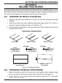
Hose Construction
Industrial gas hose used in the U.S. is generally color-coded for gas service identification. The
oxygen hose is normally green and the fuel hose is red. The colors are subject to change in
countries other than the U.S. The hose walls are constructed of continuous layers of rubber or
neoprene material over a braided inner section. The hose is marked to indicate its grade. All
approved domestically fabricated type VD grade “RM” and “T” hoses are flame retardant and
have an oil resistant cover. Grade “R” hose does not have an oil resistant cover. Grade “T” and
“RM” hose will burn, but will not support a flame if the heat source is removed. Grade “T” hose
is recommended for all fuel gases. Grade “R” and “RM” hose is for use with acetylene only.
WARNING
Grade “R” and “RM” hose are for use with acetylene only. These hoses have
rubber linings that are degraded by petroleum-based fuel gases. Grade “T” hose is
recommended for all fuel gases. It should be used with petroleum-based fuel gases
since it has a neoprene inner liner that is compatible with these gases.
Hose Care
Gas hoses are often exposed to severe abuse. They can provide efficient service with proper care.
Hose splices and excessive hose length can restrict and reduce the amount of gas flow within the
hose. Molten slag and sparks may come into contact with hoses and burn into the hose exterior.
Falling metal during cutting operations might crush or cut into gas hoses. The operator should
frequently inspect the hoses and, when necessary, replace them.

SET-UP AND SAFE OPERATING PROCEDURES
4-150056-3260
Oxy-Fuel Apparatus
Safety Notes
• Falling metal during cutting operations might crush or cut into gas hoses.
• Never allow hoses to become coated with oil, grease, or dirt. Such coatings could conceal
damaged areas.
• Examine the hoses before attaching them to the gas torch handle or regulators. If cuts,
burns, cracks, worn areas, or damaged fittings are found, replace the hose.
• Completely replace the gas hose if it contains multiple splices or when cracks or severe
wear is noticed.
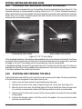
TERMS YOU SHOULD KNOW
BACKFIRE - The return of the flame into the torch, producing a popping sound. The flame will
either extinguish or re-ignite at the tip.
SUSTAINED BACKFIRE - The return of the flame into the torch with continued burning within the torch. This
condition may be accompanied by a popping sound followed by a continuous hissing or whistling sound.
FLASHBACK - The return of the flame through the torch into the hose and even into the regulator.
It may also reach the cylinder. This condition could possibly cause an explosion in the system.
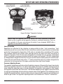
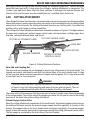
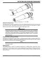
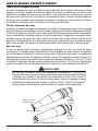
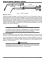
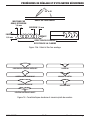
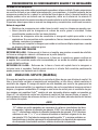
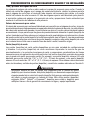
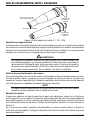
4.03 TORCH HANDLE
A torch handle is essentially a set of gas tubes with control valves. One tube and valve controls
the fuel supply and the other tube and valve controls the oxygen supply. The torch handle is not
designed to mix the gases for oxy-fuel processes. The apparatus attached to the handle mixes
the oxygen and fuel gases. The handle is a means of control for the gas supply.
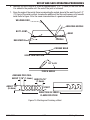
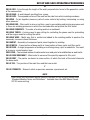
Victor
®
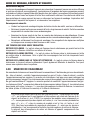
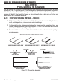
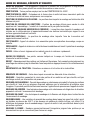
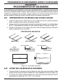
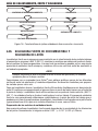
torch handles consists of six basic elements, shown in Figure 4. The control valves with
internal reverse flow check valves, the body “Y” with internal flashback arrestors, the barrel and
tubes (located inside the barrel) and the torch head.
NOTE
Victor
®
torch handle model numbers that contain the letters “FC” are equipped with
built-in flashback arrestors and check valves (i.e 315FC). Model numbers with a “C”
only contain built-in check valves (i.e. 315C). Earlier versions without an “F” or “C”
in the model number contain neither (i.e. 315). For all “C” model torch handles and
earlier versions, it is recommended that add-on flashback arrestors be installed.
Most add-on flashback arrestors also contain built-in check valves.
BODY “Y”
BARREL
TORCH HEAD
CONTROL
VALVES
INTERNAL REVERSE FLOW
CHECK VALVES
INTERNAL FLASHBACK
ARRESTORS
Figure 4: Torch Handle Features

4-16
CUTTING, HEATING AND WELDING GUIDE
0056-3260
Oxy-Fuel Apparatus
Body “Y” with Internal Flashback Arrestors
Most Victor
®
torch handles are equipped with built-in flashback arrestors. Flashback arrestors
are designed to prevent mixed gases from igniting upstream of the flashback arrestors.
CAUTION
It is not recommended to use accessory flashback arrestors on Victor
®
FC torch handles
since these devices are already built-in. Excessive flow restrictions may occur.
General Information on Flashback Arrestors
• The flashback arrestors contained in this torch are designed to prevent a flashback flame
from entering the hose and gas supply system. A very fine “filter-like” sintered stainless
steel flame barrier stops flashback flame.
• For maximum service life of the flashback arrestor, completely purge all lines and hoses
before connecting to the torch. This removes loose material contained in the hose or
regulator that could restrict flow through the flashback arrestor.
• Flow restriction and torch over-heating results if dirt or “oily” LPG residuals are allowed to
flow into the flashback arrestor and cause clogging. Make sure not to draw liquid. Always
store and use cylinders in the upright position.
Control Valves with Internal Reverse Flow Check Valves
The body “Y” has two control valves attached to it. The valve bodies are marked to distinguish
between the two valves. The body of one valve has left-hand threads to accept the fuel gas hose.
The other valve body has right-hand threads to accept the oxygen hose. The control valves never
require lubricating. Occasionally, the packing nuts may require a slight adjustment.
Most Victor
®
torch handles are equipped with patented built-in reverse flow check valves to
reduce the possibility of mixing gases in the hoses and regulators.
CAUTION
Check valves are mechanical devices that can leak when dirty or if abused. Check
valves should be tested at least every six months, more often if hoses are frequently
disconnected. Careless usage, dirt or abuse can shorten the service life of check
valves, thus requiring more frequent testing. Follow the manufacture’s instructions
for testing the check valves.
NOTE
Reverse flow check valves are not the same as flashback arrestors. Check valves
are designed to help prevent reverse flow of gas upstream of the torch. Flashback
arrestors are designed to prevent mixed gases from igniting upstream of the
flashback arrestors.
Barrel
The barrel and inner oxygen tube unit is designed to keep the oxygen and fuel gases separated. A
tube-within-a-tube design allows the oxygen supply to move through the inner tube to the head
while the fuel supply travels through the interior barrel cavity.
Torch Head
The torch head is threaded onto the barrel, creating a metal to metal seal; there are no O-rings.
The oxygen supply from the inner tube is directed through the center hole in the head while the
La page est en cours de chargement...
La page est en cours de chargement...
La page est en cours de chargement...
La page est en cours de chargement...
La page est en cours de chargement...
La page est en cours de chargement...
La page est en cours de chargement...
La page est en cours de chargement...
La page est en cours de chargement...
La page est en cours de chargement...
La page est en cours de chargement...
La page est en cours de chargement...
La page est en cours de chargement...
La page est en cours de chargement...
La page est en cours de chargement...
La page est en cours de chargement...
La page est en cours de chargement...
La page est en cours de chargement...
La page est en cours de chargement...
La page est en cours de chargement...
La page est en cours de chargement...
La page est en cours de chargement...
La page est en cours de chargement...
La page est en cours de chargement...
La page est en cours de chargement...
La page est en cours de chargement...
La page est en cours de chargement...
La page est en cours de chargement...
La page est en cours de chargement...
La page est en cours de chargement...
La page est en cours de chargement...
La page est en cours de chargement...
La page est en cours de chargement...
La page est en cours de chargement...
La page est en cours de chargement...
La page est en cours de chargement...
La page est en cours de chargement...
La page est en cours de chargement...
La page est en cours de chargement...
La page est en cours de chargement...
La page est en cours de chargement...
La page est en cours de chargement...
La page est en cours de chargement...
La page est en cours de chargement...
La page est en cours de chargement...
La page est en cours de chargement...
La page est en cours de chargement...
La page est en cours de chargement...
La page est en cours de chargement...
La page est en cours de chargement...
La page est en cours de chargement...
La page est en cours de chargement...
La page est en cours de chargement...
La page est en cours de chargement...
La page est en cours de chargement...
La page est en cours de chargement...
La page est en cours de chargement...
La page est en cours de chargement...
La page est en cours de chargement...
La page est en cours de chargement...
La page est en cours de chargement...
La page est en cours de chargement...
La page est en cours de chargement...
La page est en cours de chargement...
La page est en cours de chargement...
La page est en cours de chargement...
La page est en cours de chargement...
La page est en cours de chargement...
La page est en cours de chargement...
La page est en cours de chargement...
La page est en cours de chargement...
La page est en cours de chargement...
La page est en cours de chargement...
La page est en cours de chargement...
La page est en cours de chargement...
La page est en cours de chargement...
La page est en cours de chargement...
La page est en cours de chargement...
La page est en cours de chargement...
La page est en cours de chargement...
La page est en cours de chargement...
La page est en cours de chargement...
La page est en cours de chargement...
La page est en cours de chargement...
La page est en cours de chargement...
La page est en cours de chargement...
La page est en cours de chargement...
La page est en cours de chargement...
La page est en cours de chargement...
La page est en cours de chargement...
La page est en cours de chargement...
La page est en cours de chargement...
La page est en cours de chargement...
La page est en cours de chargement...
La page est en cours de chargement...
La page est en cours de chargement...
La page est en cours de chargement...
La page est en cours de chargement...
La page est en cours de chargement...
La page est en cours de chargement...
La page est en cours de chargement...
La page est en cours de chargement...
La page est en cours de chargement...
La page est en cours de chargement...
La page est en cours de chargement...
La page est en cours de chargement...
La page est en cours de chargement...
La page est en cours de chargement...
La page est en cours de chargement...
La page est en cours de chargement...
La page est en cours de chargement...
La page est en cours de chargement...
La page est en cours de chargement...
La page est en cours de chargement...
La page est en cours de chargement...
La page est en cours de chargement...
La page est en cours de chargement...
La page est en cours de chargement...
La page est en cours de chargement...
La page est en cours de chargement...
La page est en cours de chargement...
La page est en cours de chargement...
La page est en cours de chargement...
La page est en cours de chargement...
La page est en cours de chargement...
La page est en cours de chargement...
La page est en cours de chargement...
La page est en cours de chargement...
La page est en cours de chargement...
La page est en cours de chargement...
La page est en cours de chargement...
La page est en cours de chargement...
La page est en cours de chargement...
La page est en cours de chargement...
La page est en cours de chargement...
La page est en cours de chargement...
La page est en cours de chargement...
La page est en cours de chargement...
La page est en cours de chargement...
La page est en cours de chargement...
La page est en cours de chargement...
La page est en cours de chargement...
La page est en cours de chargement...
La page est en cours de chargement...
La page est en cours de chargement...
La page est en cours de chargement...
La page est en cours de chargement...
La page est en cours de chargement...
La page est en cours de chargement...
La page est en cours de chargement...
La page est en cours de chargement...
La page est en cours de chargement...
La page est en cours de chargement...
La page est en cours de chargement...
La page est en cours de chargement...
La page est en cours de chargement...
La page est en cours de chargement...
La page est en cours de chargement...
La page est en cours de chargement...
La page est en cours de chargement...
La page est en cours de chargement...
La page est en cours de chargement...
La page est en cours de chargement...
La page est en cours de chargement...
-
 1
1
-
 2
2
-
 3
3
-
 4
4
-
 5
5
-
 6
6
-
 7
7
-
 8
8
-
 9
9
-
 10
10
-
 11
11
-
 12
12
-
 13
13
-
 14
14
-
 15
15
-
 16
16
-
 17
17
-
 18
18
-
 19
19
-
 20
20
-
 21
21
-
 22
22
-
 23
23
-
 24
24
-
 25
25
-
 26
26
-
 27
27
-
 28
28
-
 29
29
-
 30
30
-
 31
31
-
 32
32
-
 33
33
-
 34
34
-
 35
35
-
 36
36
-
 37
37
-
 38
38
-
 39
39
-
 40
40
-
 41
41
-
 42
42
-
 43
43
-
 44
44
-
 45
45
-
 46
46
-
 47
47
-
 48
48
-
 49
49
-
 50
50
-
 51
51
-
 52
52
-
 53
53
-
 54
54
-
 55
55
-
 56
56
-
 57
57
-
 58
58
-
 59
59
-
 60
60
-
 61
61
-
 62
62
-
 63
63
-
 64
64
-
 65
65
-
 66
66
-
 67
67
-
 68
68
-
 69
69
-
 70
70
-
 71
71
-
 72
72
-
 73
73
-
 74
74
-
 75
75
-
 76
76
-
 77
77
-
 78
78
-
 79
79
-
 80
80
-
 81
81
-
 82
82
-
 83
83
-
 84
84
-
 85
85
-
 86
86
-
 87
87
-
 88
88
-
 89
89
-
 90
90
-
 91
91
-
 92
92
-
 93
93
-
 94
94
-
 95
95
-
 96
96
-
 97
97
-
 98
98
-
 99
99
-
 100
100
-
 101
101
-
 102
102
-
 103
103
-
 104
104
-
 105
105
-
 106
106
-
 107
107
-
 108
108
-
 109
109
-
 110
110
-
 111
111
-
 112
112
-
 113
113
-
 114
114
-
 115
115
-
 116
116
-
 117
117
-
 118
118
-
 119
119
-
 120
120
-
 121
121
-
 122
122
-
 123
123
-
 124
124
-
 125
125
-
 126
126
-
 127
127
-
 128
128
-
 129
129
-
 130
130
-
 131
131
-
 132
132
-
 133
133
-
 134
134
-
 135
135
-
 136
136
-
 137
137
-
 138
138
-
 139
139
-
 140
140
-
 141
141
-
 142
142
-
 143
143
-
 144
144
-
 145
145
-
 146
146
-
 147
147
-
 148
148
-
 149
149
-
 150
150
-
 151
151
-
 152
152
-
 153
153
-
 154
154
-
 155
155
-
 156
156
-
 157
157
-
 158
158
-
 159
159
-
 160
160
-
 161
161
-
 162
162
-
 163
163
-
 164
164
-
 165
165
-
 166
166
-
 167
167
-
 168
168
-
 169
169
-
 170
170
-
 171
171
-
 172
172
-
 173
173
-
 174
174
-
 175
175
-
 176
176
-
 177
177
-
 178
178
-
 179
179
-
 180
180
-
 181
181
-
 182
182
-
 183
183
-
 184
184


Victor Heating and Welding Guide Manuel utilisateur
- Taper
- Manuel utilisateur
- Ce manuel convient également à
dans d''autres langues
Autres documents
-
ESAB OXWELD CW-400 Manuel utilisateur
-
-
-
-
-
Harris 4403249 Mode d'emploi
-
-
-
-