Maytag MED6300TQ - 29" Front-Load Electric Dryer Mode d'emploi
- Catégorie
- Sèche-linge électriques
- Taper
- Mode d'emploi

®
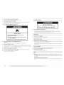
BRAVOS TMFABRIC CARE SYSTEM ELECTRIC DRYER
USE & CARE GUIDE
SECADORA ELECTRICA BRAVOS TMCON
CUIDADO DE LA TELAS
MANUAL DE USO Y CUIDADO
SISTEMA DE
SECHEUSE ELECTRIQUE BRAVOS T_AVEC SYSTEME DE
SOIN DES TISSUS
GUIDE D'UTILISATION ET D'ENTRETIEN
Z
FOR QUESTIONS ABOUT FEATURES, OPERATION/PERFORMANCE,
PARTS, ACCESSORIES OR SERVICE CALL: 1.800.688.9900
IN CANADA, CALL: 1,800,807,6777
VISIT OUR WEBSITE AT WWW.MAYTAG,COM
IN CANADA, WWW, MAYTAG.CA
SI TIENE PREGUNTAS RESPECT() A LAS CARACTERiSTICA8,
FUNCIONAMIENTO, RENDIMIENTO, PARTES, ACCESORIOS O
SERVICIO TI_CNICO, LLAME AL: 1,800,688,9900
O VISITE NUESTRO SITIO WEB EN
WWW.MAYTAG,COM
AU CANADA, POUR ASSISTANCE, INSTALLATION OU SERVICE,
COMPOSER LE : 1,800,807,6777
OU VISITEZ NOTRE SITE {NTERNET _,
WWW.MAYTAG.CA
W10088777A

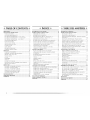
@ TABLE OF CONTENTS @
DRYER SAFETY ..................................................................... 3
INSTALLATION INSTRUCTIONS ........................................ 4
TOOI.S AND PARTS .......................................................... 4
EOCATION REQUIREMENTS ........................................... 4
El ECTRICAL REQUIREMENTS - U.S.A. ONI.Y ................... 5
El ECTRICAI. REQ)UIREMENTS - CANADA ONI.Y ............. 7
EEECTRICAL CONNECTION - U.S.A. ONI.Y ..................... 8
VENTING REQ)UIREMENTS ............................................. 14
PI.AN VENT SYSTEM ....................................................... 16
INSFAH. VENT SYSTEM ................................................... 17
INSFAH. EEVEHNG EEGS ................................................ 17
CON NECF VENT ............................................................. 18
EEVEI. [DRYER................................................................... 18
REVERSE DOOR SWING ................................................. 18
COMPI.ETE INSTAL I ATION ............................................ 20
DRYER USE ......................................................................... 21
STAR[ING YOUR [DRYER................................................ 21
STOPPING, PAUSING OR RESTARTING ........................ 22
DRYING AND CYCI.E TIPS .............................................. 22
STATUS HGHTS .............................................................. 23
CYCI.ES ............................................................................ 23
MODIFIERS ...................................................................... 24
OPTIONS ......................................................................... 25
END OF CYCI.E SIGNAl ................................................... 25
CHANGING CYCI.ES, MODIFIERS AND OPTIONS ........ 25
DRYING RACK OPTION ................................................. 26
DRYER CARE ...................................................................... 27
(_I.EANING THE [DRYER I.OCATION ............................... 27
CLEANING THE LINT SCREEN ........................................ 27
CI.EANING THE [DRYER INTERIOR ................................. 28
REMOVING ACCUMUI.ATE[D I.INT ................................ 28
VACATION AND MOVING CARE .................................. 28
CHANGING THE DRUM I.IGHT ..................................... 28
TROUBLESHOOTING ........................................................ 29
ASSISTANCE OR SERVICE .................................................. 31
WARRANTY ....................................................................... 32
P
@ INDICE @
SEGURIDAD DE LA SECADORA ....................................... 33
INSTRUCCIONES DE INSTALACION ............................... 34
HERRAMIENTAS Y PIEZAS .............................................. 34
REQUISITOS [DE UBICACION ....................................... 35
REQ)UISITOS EI.ECTRICOS - S(_)[O EN EE. UU ............... 36
CONEXION EI.ECTRICA - S(_)I.O EN EE. UU ................... 38
REQ)UISITOS [DEVENTI[ ACION ..................................... 44
PEANIFICACI(£_N DE[ SISFEMA DE VENTIEACI('£_N ....... 46
INSTAI_ACION [)El. SISTEMA DE VENTH.ACIt'gN ........... 47
INSTAI.ACION DE I.AS PATAS NIVEI.ADORAS .............. 48
CONEXION DEE DUCFO [DE ESCAPE ............................ 48
NIVEEACI('£_N DE EA SECADORA ................................... 48
COMO INVERTIR El. CIERRE DE I.A PUERTA ................. 49
COMPLETE [A INSTALACION ........................................ 51
USO DE LA SECADORA .................................................... 51
PUESTA EN MARCHA [DE EA SECADORA ..................... ._2
C(_)MO DETENER, PAUSAR Y VOEVER A PONER
EN MARCHA ................................................................... 53
SUGERENCIAS [DECICLOS Y SECADO .......................... 53
EUCES DE ESTADO ......................................................... 54
CICI.OS ........................................................................... 54
MODIFICADORES .......................................................... 55
OPCIONES ...................................................................... 56
SENAL [DE FIN DE CICLO ............................................... 57
CAMBIO DE CICI.OS, MODIFICADORES Y
OPCIONES ...................................................................... 57
OPCION [DE ESTANTE [DESECADO ............................... 58
CUIDADO DE LA SECADORA .......................................... 59
I IMPIEZA DEI. I.UGAR DONDE ESFz_I.A SECADORA...._9
EIMPIEZA DEI. FILFRO DE PEI.USA ................................ 59
EIMPIEZA DEE INTERIOR DE EA SECADORA ................ 59
EHMINACI(_)N DE PEEUSA ACUMUI.ADA .................... 60
CUIDADO DURANTE EAS VACACIONES
Y MUDANZAS ................................................................ 60
CAMBIO DE EA EUZ DEE TAMBOR ............................... 60
SOLUClON DE PROBLEMAS ............................................ 61
AYUDA O SERVICIO Tf_CNICO ........................................ 63
GARANTiA ........................................................................ 64
@ TABLE DES MATIERES @
SECURITIE DE LA SECHEUSE .............................................. 65
INSTRUCTIONS D'I NSTALLATION .................................. 66
OUIII I.AGE ET PIECES .................................................... 66
EXIGENCES D'EMPI.ACEMENT. ...................................... 67
SPECIFICATIONS EEECTRIQUES - POUR LE CANADA
SEUI.EMENT. ................................................................... 68
EXIGENCES CONCERNANT I.'EVACUAT[ON ................ 69
PI.ANIFICAFION DU SYSI-EME D'EVACUATION ........... 70
INSI-AL[AFION DU SYSTEME D'EVACUAFION ............ 72
INSI-AI.I.ATION [DES PIEDS [DENIVEH.EMENT ............... 72
RACCORDEMENT DU CONDUIT D'[_VACUAFION ...... 72
REG[ AGE [DE UAPEOMB [DE I.A SI_CHEUSE ................... 72
INVERSION DU SENS D'OUVERTURE DE LA PORTE.... 73
ACHEVER I.'INSI-AI.I.ATION ........................................... 75
UTILISATION DE LA Sf_CHEUSE ....................................... 75
MISE EN MARCHE DE [A SECHEUSE ............................. 76
ARRET, PAUSE OU REMISE EN MARCHE ....................... 77
CONSEII_S POUR I.E SECHAGE ET LES
PROGRAMMES ............................................................... 77
TEMOINS LUMINEUX ..................................................... 78
PROGRAMMES ............................................................... 78
MODIFICATEURS ............................................................ 79
OPTIONS ......................................................................... 80
SIGNAl_ DE FIN DE PROGRAMME ................................. 80
CHANGEMENT E)ES PROGRAMMES, MODIFICATEURS
ET OPTIONS .................................................................... 81
OPTION DE GRII.I E [DE SECHAGE ................................. 81
ENTRETIEN DE LA SI_CHEUSE ........................................... 82
NETTOYAGE [DE I.'EMPI.ACEMENT DE EA SECHEUSE... 82
NETTOYAGE DU FII.TRE _, CHARPIE ............................. 82
NETTOYAGE DE L'IN-I [_RIEUR DE I.A SECHEUSE ........... 83
RETRAIT DE [A CHARPIE ACCUMUI.EE ......................... 83
PRECAUTIONS A PREN[)RE POUR LES VACANCES
EF AVANT UN DEMENAGEMENT. ................................. 83
CHANGEMENT [DE I 'AMPOUI E D'ECI AIRAGE
DU TAMBOUR ................................................................ 83
DEPANNAGE ..................................................................... 84
ASSISTANCE OU SERVICE ................................................. 86
GARANTIE ......................................................................... 87

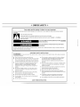
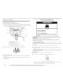
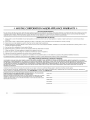
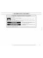
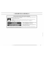
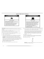
DRYER SAFETY
Your safety and the safety of others are very important.
We have provided many important safety messages in this manual and on your appliance. Always read and obey all safety
messages.
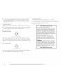
This is the safety alert symbol.
This symbol alerts you to potential hazards that can kill or hurt you and others.
All safety messages will follow the safety alert symbol and either the word "DANGER" or "WARNING."
These words mean:
You can be killed or seriously injured if you don't immediately
follow instructions.
You can be killed or seriously injured if you don't follow
instructions.
All safety messages will tell you what the potential hazard is, tell you how to reduce the chance of injury, and tell you what can
happen if the instructions are not followed.
I
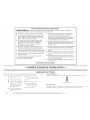
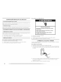
iMPORTANT SAFETY iNSTRUCTiONS
WARNING: To reduce the risk of fire, electric shock, or injury to persons when using the dryer, follow basic precautions,
including the following:
[] Read all instructions before using the dryer.
[] Do not place items exposed to cooking oils in your dryer.
Items contaminated with cooking oils may contribute to
a chemical reaction that could cause a load to catch fire.
[] Do not dry articles that have been previously cleaned in,
washed in, soaked in, or spotted with gasoline, dry-
cleaning solvents, or other flammable or explosive
substances as they give off vapors that could ignite or
explode.
[] Do not allow children to play on or in the dryer. Close
supervision of children is necessary when the dryer is
used near children.
[] Before the dryer is removed from service or discarded,
remove the door to the drying compartment.
[] Do not reach into the dryer if the drum is moving.
[] Do not install or store the dryer where it will be exposed
to the weather.
[] Do not tamper with controls.
[] Do not repair or replace any part of the dryer or attempt
any servicing unless specifically recommended in this
Use and Care Guide or in published user-repair
instructions that you understand and have the skills to
carry out.
[] Do not use fabric softeners or products to eliminate static
unless recommended by the manufacturer of the fabric
softener or product.
[] Do not use heat to dry articles containing foam rubber or
similarly textured rubber-like materials.
[] Clean lint screen before or after each load.
[] Keep area around the exhaust opening and adjacent
surrounding areas free from the accumulation of lint, dust,
and dirt.
[] The interior of the dryer and exhaust vent should be
cleaned periodically by qualified service personnel.
[] See installation instructions for grounding requirements.
SAVETHESEINSTRUCTIONS

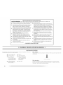
INSTALLATION INSTRUCTIONS
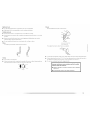
TOOLS AND PARTS
Gather the required tools and parts before starting installation. Read and follow the
instructions provided with any tools listed here.
Flat-blade screwdriver
#2 Phillips screwdriver
Adjustable wrench that
opens to 1" (2.5 cm) or
hex-head socket wrench
(for adjusting dryer feet)
Wire stripper (direct wire
installations/
• Tin snips/new vent
installations/
Eevel
Vent clamps
Caulking gun and
compound (for installing
new exhaust vent)
[_tpe measure
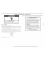
Parts supplied:
Remove parts package from dryer drum. Check that all parts were included.
4 leveling legs
Parts needed:
Check local codes. Check existing electrical supply and venting and see "Electrical
Requirements" and "Venting Requirements" before purchasing parts.
Mobile home installations require metal exhaust system hardware available for purchase from
the dealer from whom you purchased your dryer. For information on ordering, please refer to
the "Assistance or Service" section of this manual. You may also contact the dealer from
whom you purchased your dryer.
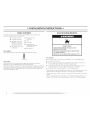
LOCATION REQUIREMENTS
Explosion Hazard
Keep flammable materials and vapors, such as
gasoline, away from dryer.
Place dryer at least 18 inches (46 cm) above the floor
for a garage installation.
Failure to do so can result in death, explosion, or fire.
You will need
• A location that allows for proper exhaust installation. See "Venting Requirements."
• A separate 30-amp circuit.
• If you are using a power supply cord, a grounded electrical outlet located within 2 ft
(61 cm) of either side of the dryer. See "Electrical Requirements."
• A sturdy floor to support the total weight (dryer and load) of 200 Ibs (90.7 kg). The
combined weight of a companion appliance should also be considered.
• A level floor with a maximum slope of 1" (2.5 cm) under entire dryer.
Do not operate your dryer at temperatures below 45°F (7°C). At lower temperatures, the dryer
might not shut off at the end of an automatic cycle. Drying times can be extended.
[he dryer must not be installed or stored in an area where it will be exposed to water and/or
weather.
Check code requirements. Some codes limit, or do not permit, installation of the dryer in
garages,closets,mobile homes or sleeping quarters. Contact your local building inspector.
4

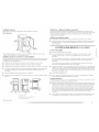
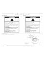
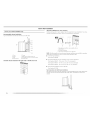
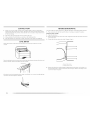
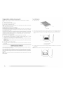
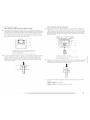
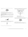
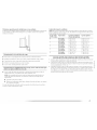
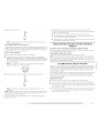
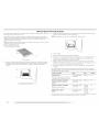
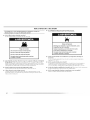
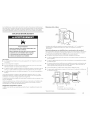
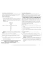
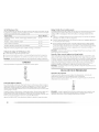
Installation Clearances
The location must be large enough to allow the dryer door to open fully.
Dryer Dimensions
*Most installations require a minimum 5" (12.7 cm) clearance behind the dryer for the
exhaust vent with elbow. See "Venting Requirements."
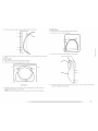
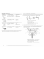
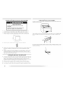
Installation spacing for recessed area or closet installation
The following spacing dimensions are recommended for this dryer. This dryer has been tested
for spacing of 0" (0 cm) clearance on the sides and rear. Recommended spacing should be
considered for the following reasons:
• Additional spacing should be considered for ease of installation and servicing.
• Additional clearances might be required for wall, door and floor moldings.
• Additional spacing should be considered on all sides of the dryer to reduce noise transfer.
• For closet installation, with a door, minimum ventilation openings in the top and bottom
of the door are required. [ ouvered doors with equivalent ventilation openings are
acceptable.
• Companion appliance spacing should also be considered.
• Additional spacing is required if you exhaust out the rear of the dryer to either the right or
left side.
i' rtx;
r' _ _- 29"_ I_-1" -_lv'*l_ 99,l_"_4_"
(9.5cm) (2.5cm)
m
48in. 2.
(319cm2i- "[_"
24in.2.
(73.7cm) (2.5cm)(74.3cm)(12.7crn)
A B C
31,,
_6cm)
__ 3"*
(7.6crn)
7
A. Recessed area
B. Side view - closet or confined area
C. Closet door with w_nts
Mobile home - Additional installation requirements
This dryer is suitable for mobile home installations. The installation must conform to the
Manufactured Home Construction and Safety Standard, Title 24 CFR, Part 3280 (formerly the
Federal Standard for Mobile Home Construction and Safety, Title 24, HUD Part 280) or
Standard CAN/CSA-Z240 MH.
Mobile home installations require:
• Metal exhaust system hardware, which is available for purchase from your dealer.
• Special provisions must be made in mobile homes to introduce outside air into the dryer.
The opening (such as a nearby window) should be at least twice as large as the dryer
exhaust opening.
ELECTRICAL REQUIREMENTS - U.S.A. ONLY
It is your responsibility
• [b contact a qualified electrical installer.
• [b be sure that the electrical connection is adequate and in conformance with the
National Electrical Code, ANSI/NFPA 70-latest edition and all local codes and
ordinances.
The National Electric Code requires a 4-wire power supply connection for homes built
after 1996, dryer circuits involved in remodeling after 1996, and all mobile home
installations.
A copy of the above code standards can be obtained from: National Fire Protection
Association, One Batterymarch Park, Quincy, MA 02269.
• lb supply the required _ or 4 wire, single phase, 120/240 volt, 60 Hz., AC only electrical
supply (or ¢ or 4 wire, 120/208 volt electrical supply, if specified on the serial/rating plate)
on a separate 30-amp circuit, fused on both sides of the line. A time-delay fuse or circuit
breaker is recommended. Connect to an individual branch circuit. Do not have a fuse in
the neutral or grounding circuit.
• Do not use an extension cord.
• If codes permit and a separate ground wire is used, it is recommended that a qualified
electrician determine that the ground path is adequate.
Electrical Connection
[b properly install your dryer, you must determine the type of electrical connection you will
be using and follow the instructions provided for it here.
• [his dryer is manufactured ready to install with a 3-wire electrical supply connection. The
neutral ground conductor is permanently connected to the neutral conductor (white wire/
within the dryer. If the dryer is installed with a 4-wire electrical supply connection, the
neutral ground conductor must be removed from the external ground connector/green
screw/, and secured under the neutral terminal (center or white wire) of the terminal
block. When the neutral ground conductor is secured under the neutral terminal icenter
or white wire) of the terminal block, the dryer cabinet is isolated from the neutral
conductor.
• If local codes do not permit the connection of a neutral ground wire to the neutral wire,
see "Optional 3-wire connection" in "Electrical Connection - U.S.A. Only" section.
*Required spacing
5
I

A4-wirepowersupplyconnectionmustbeusedwhentheapplianceisinstalledina
locationwheregroundingthroughtheneutralconductorisprohibited.Grounding
throughtheneutralisprohibitedfor(1)newbranch-circuitinstallations,(2)mobile
homes,(3)recreationalvehicles,and(4)areaswherelocalcodesprohibitgrounding
throughtheneutralconductors.
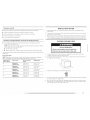
Ifusing a power supply cord:
Use a UL listed power supply cord kit marked for use with clothes dryers. The kit should
contain:
[] A Ui listed 30-amp power supply cord, rated 120/240 volt minimum. ]he cord should be
type SRD or SRDT and be at least 4 ft (1.22 m) long. ]he wires that connect to the dryer
must end in ring terminals or spade terminals with upturned ends.
[] A UI listed strain relief.
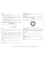
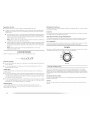
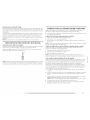
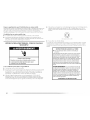
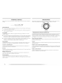
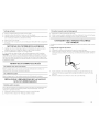
If your outlet looks like this:
4-wirt" rt'cept_cl_' (14-30R)
Then choose a 4-wire power supply cord with ring or spade terminals and U[. listed strain
relief. [he 4-wire power supply cord, at least 4 ft (1.22 m) long, must have four 10-gauge
copper wires and match a 4-wire receptacle of NEMA Type 14-30R. The ground wire (ground
conductor) may be either green or bare. The neutral conductor must be identified by a white
cover.
If your outlet looks like this:
3-wire" re'cept_cle' (lO-30R)
Then choose a 3-wire power supply cord with ring or spade terminals and U[ listed strain
relief. [he 3-wire power supply cord, at least 4 ff (1.22 m) long, must have three 10-gauge
copper wires and match a 3-wire receptacle of NEMA Type 10-30R.
If connecting by direct wire:
Power supply cable must match power supply (4-wire or 3-wire) and be:
[] Flexible armored cable or nonmetallic sheathed copper cable (with ground wire),
protected with flexible metallic conduit. All current-carrying wires must be insulated.
[] 10-gauge solid copper wire (do not use aluminum).
[] At least 5 ft (1.52 m) long.
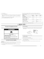
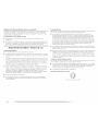
GROUNDING INSTRUCTIONS
[] For a grounded, cord-connected dryer:
This dryer must be grounded. In the event of malfunction or
breakdown, grounding will reduce the risk of electric shock
by providing a path of least resistance for electric current.
This dryer uses a cord having an equipment-grounding
conductor and a grounding plug. The plug must be plugged
into an appropriate outlet that is properly installed and
grounded in accordance with all local codes and ordinances.
[] For a permanently connected dryer:
This dryer must be connected to a grounded metal,
permanent wiring system, or an equipment-grounding
conductor must be run with the circuit conductors and
connected to the equipment-grounding terminal or lead on
the dryer.
WARNING: Improper connection of the equipment-
grounding conductor can result in a risk of electric shock.
Check with a qualified electrician or service representative
or personnel if you are in doubt as to whether the dryer is
properly grounded. Do not modify the plug on the power
supply cord: if it will not fit the outlet, have a proper outlet
installed by a qualified electrician.
SAVE THESE INSTRUCTIONS
6

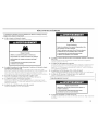
ELECTRICAL REQUIREMENTS - CANADA ONLY
Electrical Shock Hazard
Plug into a grounded 4 prong outlet.
Failure to do so can result in death or electrical shock.
It is your responsibility
• [b contact a qualified electrical installer.
• [b be sure that the electrical connection is adequate and in conformance with the
Canadian Electrical Code, C22.1 -latest edition and all local codes. A copy of the above
codes standard may be obtained from: Canadian Standards Association, 178 Rexdale
Blvd., toronto, ON M9W 1R3 CANADA.
[b supply the required 4 wire, single phase, 120/240 volt, 60 Hz., AC only electrical
supply on a separate 30-amp circuit, fused oil both sides of the line. A time-delay fuse or
circuit breaker is recommended. Connect to an individual branch circuit.
This dryer is equipped with a CSA International Certified Power Cord intended to be
plugged into a standard 14-¢0R wall receptacle. The cord is 5 ft/1.52 m) in length. Be
sure wall receptacle is within reach of dryer's final location.
If you are using a replacement power supply cord, it is recommended that you use Power
Supply Cord Replacement Part Number 3394208. For further information, please reference
the service numbers located in the "Assistance or Service" section of this manual.
GROUNDING INSTRUCTIONS
• For a grounded, cord-connected dryer:
This dryer must be grounded. In the event of malfunction or
breakdown, grounding will reduce the risk of electric shock
by providing a path of least resistance for electric current.
This dryer is equipped with a cord having an equipment-
grounding conductor and a grounding plug. The plug must
be plugged into an appropriate outlet that is properly
installed and grounded in accordance with all local codes
and ordinances.
WARNING: Improper connection of the equipment-
grounding conductor can result in a risk of electric shock.
Check with a qualified electrician or service representative
or personnel if you are in doubt as to whether the dryer is
properly grounded. Do not modify the plug provided with the
dryer: if it will not fit the outlet, have a proper outlet installed
by a qualified electrician.
SAVE THESE INSTRUCTIONS
4wvire receptacle 14-30R
• Do not use an extension cord.
I

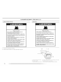
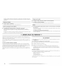
ELECTRICAL CONNECTION - U.S.A. ONLY
Power Supply Cord
Fire Hazard
Use a new UL listed 30 amp power supply cord.
Use a UL listed strain relief.
Disconnect power before making electrical connections.
Connect neutral wire (white or center wire) to center
terminal (silver).
Ground wire (green or bare wire) must be connected to
green ground connector.
Connect remaining 2 supply wires to remaining
2 terminals (gold).
Securely tighten all electrical connections.
Failure to do so can result in death, fire, or
electrical shock.
Direct Wire
Fire Hazard
Use 10 gauge solid copper wire.
Use a UL listed strain relief.
Disconnect power before making electrical connections.
Connect neutral wire (white or center wire) to center
terminal (silver).
Ground wire (green or bare wire) must be connected to
green ground connector.
Connect remaining 2 supply wires to remaining
2 terminals (gold).
Securely tighten all electrical connections.
Failure to do so can result in death, fire, or
electrical shock.
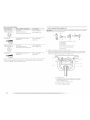
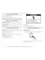
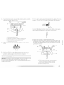
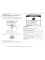
1. Disconnect power.
2. Remove the hold-down screw and terminal block cover.
AB
E
F
A. 7_rminal block co_,er D. Center, silw_r-colored terminal block screw
B. Hold-down screw E. Neutral ground wile
C. External ground conductor screw [. Hole below terminal block opening

3. Install strain relief.
Style 1: Power supply cord strain relief
• Remove the screws from a %" (1.9 cm) UI. listed strain relief (UI marking on strain relief).
Put the tabs of the two clamp sections into the hole below the terminal block opening so
that one tab is pointing up and the other is pointing down, and hold in place. Tighten
strain relief screws just enough to hold the two clam[) sections togethen
A. Strain relief tab pointing up
B. Hole' below terminal block opening
C. Clamp section
D. Strain relief tab pointing down
Put power supply cord through the strain relief. Be sure that the wire insulation on the
power supply cord is inside the strain relief. The strain relief should have a tight fit with
the dryer cabinet and be in a horizontal position. Do not further tighten strain relief
screws at this point.
Style 2: Direct wire strain relief
Unscrew the removable conduit connector and any screws from a 3/4"(1.9 cm) U[. listed
strain relief (UI. marking on strain relief). Put the threaded section of the strain relief
through the hole below the terminal block opening. Reaching inside the terminal block
opening, screw the removable conduit connector onto the strain relief threads.
A. Removable conduit connector
B. Hole' below t_'rmina] block opening
C. Strain relief threads
Put direct wire cable through the strain relief. ]he strain relief should have a tight fit with
the dryer cabinet and be in a horizontal position. Tighten strain relief screw against the
direct wire cable.
Now complete installation following instructions for your type of electrical connection:
4-wire (recommended)
3-wire (if 4-wire is not available)

ElectricalConnection Options
If your home has: And you will be connecting to: Go to Section:
4-wire receptacle A UI. listed, 4-wire connection:
iNEMA type 14-30R) 120/240-volt minimum, Power Supply Cord
(_ 30-amp, dryer power supply cord*
4-wire direct A fused disconnect or circuit 4-wire connection:
breaker box* Direct Wire
(12.7 cm)
3-wire receptacle
(NEMA type 10-30R)
©
A UI. listed,
120/240-volt minimum,
30-amp, dryer power supply cord*
3-wire connection:
Power Supply Cord
3-wire direct A fused disconnect or circuit 3-wire connection:
breaker box* Direct Wire
*If local codes do not _ermit the connection of a cabinet-ground conductor to tile neutral
wire, go to "Optional 3-wire connection" section.
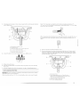
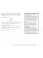
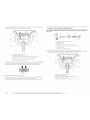
4-wire connection: Power supply cord
IMPORTANT: A 4-wire connection is required for mobile homes and where local codes do
not permit the use of 3-wire connections.
B
F
C D E G
1.
2.
A. 4-wire receptacle (NEMA type 14-30R)
B. 4-prong plug
C. Ground prong
D. Neutral prong
E. Spade terminals with upturned end_
f. ?g" t 1.9 cm) U[ listed strain relief
G. Ring tenTfinals
Remove center silver-colored terminal block screw.
Remove neutral ground wire from external ground conductor screw. Connect neutral
ground wire and the neutral wire (white or center wire) of power supply cord under
center, silver-colored terminal block screw. Tighten screw.
D
A. Neutral ground wire
B. Fxternal ground conductor screw - Dotted line shows position
of NEUTRA I, ground wire before being moved to center silver-
colored terminal block screw.
C. Center silver-colored tenTlinal block screw
D. Neutral wire' (white or center wire)
E. _/4" ( 1.9 cm) U[ listed strain re'lief
10

3,
Connect ground wire (green or bare) of power supply cord to external ground conductor
screw. Tighten screw.
4,
5,
6.
A. External ground conductor screw
B. Neutral ground wire
C. Ground wire (green or bare) of power supply cord
D. _/4" ( 1.9 cm) U[ listed strain relief
E. Center silver-colored terminal block screw
[. Neutral wire twhite or center wire)
Connect the other wires to outer terminal block screws. Tighten screws.
Tighten strain relief screws.
!! !!
Insert tab of terminal block cover into slot of dryer rear panel. Secure cover with hold-
down screw.
7. You have completed your electrical connection. Now go to "Venting Requirements."
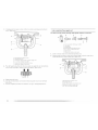
4-wire connection: Direct Wire
IMPORTANT: A 4-wire connection is required for mobile homes and where local codes do
not permit the use of 3 wire connections.
Direct wire cable must have 5 ft (1.52 m) of extra length so dryer can be moved if needed.
Strip 5" (12.7 cm) of outer covering from end of cable, leaving bare ground wire at 5"
(12.7 cm). Cut 1Vd' (3.8 cm) from 3 remaining wires. Strip insulation back 1" (2.5 cm). Shape
ends of wires into a hook shape.
(12,Z
When connecting to the terminal block, place the hooked end of the wire under the screw of
the terminal block Ihook facing right), squeeze hooked end together and tighten screw, as
shown.
1.
2.
Remove center silver-colored terminal block screw.
Remove neutral ground wire from external ground conductor screw. Connect neutral
ground wire and place the hooked end (hook facing right) of the neutral wire (white or
center wire) of direct wire cable under the center screw of the terminal block. Squeeze
hooked ends together. Tighten screw.
,,...................................:_...........................................................D
t _",
A. Neutral ground wire
B. £xternal glound conductor screw - Dotted line shows
position of NEUTRAL ground wire before being rnoved to
center silver-colored terminal block screw.
C. Center silver-co/ore'd terminal block scre'w
D. Neutral wire (white or center wire)
E. _4" ( 1.9 cm) UL listed strain relic4

3,
4,
Connect ground wire (green or bare) of direct wire cable to external ground conductor
screw. Tighten screw.
B
C
A. External ground conductor screw
B. Neutral ground wire
C. Ground wir_' Igreen or bare) of power supply cord
D. _4" ( 1.9 cm) U[ listed strain reli_'f
E. (_ulter silver-color_'d terminal block scr_'w
L Neutral wire (white or center wir_')
Place the hooked ends of the other direct wire cable wires under the outer terminal block
screws (hooks facing right). Squeeze hooked ends together. Tighten screws.
I I
5. Tighten strain relief screw.
6. Insert tab of terminal block cover into slot of dryer rear panel. Secure cover with hold-
down screw.
7. You have completed your electrical connection. Now go to "Venting Requirements."
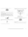
3-wire connection: Power supply cord
Use where local codes permit connecting cabinet-ground conductor to neutral wire.
A ...... /
C G F
1.
2.
A. 3-wire re'ceptacle (NFMA type lO-30R)
B. 3-wire plug
C. Neutral prong
D. Spade' te'rminah with upturned ends
E. _" (t.9 cm) U[ list_,d strain r_'lief
£ Ring t_,rminals
G. Neutral wire (white" or center wir_')
Loosen or remove center silver-colored terminal block screw.
Connect neutral wire (white or center wire) of power supply cord to the center, silver-
colored terminal screw of the terminal block. Tighten screw.
A. [xternal ground conductor scr_'w
B. Neutral ground wir_"
C. C_'nte'r silver-colored terminal block screw
D. Neutral wir_' (white of center wire)
E. _" ( 1.9 cm) U[ listed strain relief

3. Connect the other wires to outer terminal block screws. Tighten screws.
!! !!
4. Tighten strain relief screws.
5. Insert tab of terminal block cover into slot of dryer rear panel. Secure cover with hold-
down screw.
6. You have completed your electrical connection. Now go to "Venting Requirements."
3-wire connection: Direct Wire
Use where local codes permit connecting cabinet-ground conductor to neutral wire.
Direct wire cable must have 5 ft (1.52 rn) of extra length so dryer call be moved if needed.
Strip 31/2'' (8.9 cm) of outer covering from end of cable. Strip insulation back 1" (2.5 cm). If
using 3-wire cable with ground wire, cut bare wire even with outer covering. Shape ends of
wires into a hook shape.
_B.9c_
When connecting to the terminalblock, place the hooked end of the wire under the screw of
the terminal block (hook facing right),squeeze hooked end togetherand tightenscrew, as
shown.
1. Loosen or remove center silver-colored terminal block screw.
Place the hooked end of the neutral wire (white or center wire) of direct wire cable under
the center screw of terminal block (hook facing right). Squeeze hooked end together.
Tighten screw.
A. f xtemal ground conductor scre'w
B. Neutral ground wire
C. Ce'nter silver-colore'd tenTlinal block scre'w
O. Neutral wire' (white or cente'r wire)
E. _" (1.9 cm) U[ li_te'd strain relief
Place the hooked ends of the other direct wire cable wires under the outer terminal block
screws (hooks facing right). Squeeze hooked ends togethen Tighten screws.
!! !!
4. Tighten strain relief screw.
5. Insert tab of terminal block cover into slot of dryer rear panel. Secure cover with hold-
down screw.
6. You have completed your electrical connection. Now go to "Venting Requirements."
I

Optional 3-wire connection
Use for direct wire or power supply cord where local codes do not permit connecting
cabinet-ground conductor to neutral wire.
1. Remove center silver-colored terminal block screw.
2. Remove neutral ground wire from external ground conductor screw. Connect neutral
ground wire and the neutral wire (white or center wire) of power supply cord/cable under
center, silver-colored terminal block screw. Tighten screw.
3.
A. Fxt_'rnal ground colTductol screw
B. Neutral ground wir_"
C. C_'nter silver-colored t_'rminal block screw
D. Neutral wire (white or center wir_')
E. _" (1.9 cm) UL listed strain r_'li_'f
F. Grounding path determined by a qualifi_'d electrician
Connect the other wires to outer terminal block screws. Tighten screws.
!! !!
E
F
4. Tighten strain relief screws.
5. Insert tab of terminal block cover into slot of dryer rear paneh Secure cover with hold-
down screw.
6.
Connect a separate copper ground wire from the external ground conductor screw to an
adequate ground.
VENTI NG REQUI REMENTS
Fire Hazard
Use a heavy metal vent,
Do not use a plastic vent.
Do not use a metal foil vent.
Failure to follow these instructions can result in death
or fire.
WARNING: lo reduce the risk of fire, this dryer MUST BE EXHAUSTED OUTDOORS.
IMPORTANT: Observe all governing codes and ordinances.
The dryer exhaust must not be connected into any gas vent, chimney, wall, ceiling or a
concealed space of a building.
If using an existing vent system
• Clean lint from the entire length of the system and make sure exhaust hood is not plugged
with lint.
• Replace any plastic or metal foil vent with rigid or flexible heavy metal vent.
• Review Vent system chart. Modify existing vent system if necessary to achieve the best
drying performance.
If this is a new vent system
Vent material
• Use a heavy metal vent. [90 not use plastic or metal foil vent.
• 4" (10.2 cm) heavy metal exhaust vent and clamps must be used.
4" ( 10.2 cm) heavy metal exhaust v_'nt
Vent products can be purchased from your dealer or by calling Maytag Services. For more
information, see the "Assistance or Service" section of this manual.
14

Rigid metal vent
• For best drying performance, rigid metal vents are recommended.
• Rigid metal vent is recommended to avoid crushing and kinking.
Flexible metal vent
• Flexible metal vents are acceptable only if accessible for cleaning.
• Flexible metal vent must be fully extended and supported when the dryer is in its final
location.
• Remove excess flexible metal vent to avoid sagging and kinking that may result in
reduced airflow and poor performance.
• Do not install flexible metal vent in enclosed walls, ceilings or floors.
Elbows
45 ° elbows provide better airflow than 90 ° elbows,
Clamps
Good Better
Use clamps to seal all joints.
Exhaust vent must not be connected or secured with screws or other fastening devices
that extend into the interior of the duct. Do not use duct tape.
Clamp
Exhaust
Recommended hood styles are shown here.
B
I_ 4. _,
(10.2 cm)
A. Louw'red hood style
B. Box hood style
The angled hood style (shown here) is acceptable.
4"
(,02cTii--
"_'k"_ 2_/,'
(6.4 cm)
• An exhaust hood should cap the vent to keep rodents and insects from entering the home.
• Exhaust hood must be at least 12" (30.5 cm) from the ground or any object that may be in
the path of the exhaust (such as flowers, rocks or bushes, snow line, etc./.
• Do not use an exhaust hood with a magnetic latch.
Improper venting can cause moisture and lint to collect
indoors, which may result in:
[] Moisture damage to woodwork, furniture, paint, wallpaper,
carpets, etc.
[] Housecleaning problems and health problems.

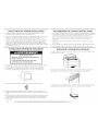
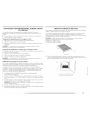
PLAN VENT SYSTEM
Choose your exhaust installation type
Recommended exhaust installations
Typical installations vent the dryer from the rear of the dryer.
A ¸
B
.........i..............................F
A. Dryer
B. Elbow
C. Wall
D. Fxhaust hood
E. Clamps
£ Rigid metal or flexible metal vent
G. Vmlt I_'ngth necessary to connect elbovw
H. Fxhaust outlet
Standard exhaust installation with rigid metal or flexible metal vent
Alternate installations for close clearances
Venting systems come in many w_rieties. Select the type best for your installation. |wo close-
clearance installations are shown. Refer to the manufacturer's instructions.
A B C
A. Over-the-top installation (also available with one
offset elbow)
B.P_'riscope inst_llation
C. Rear exhaust installadon to left or right sidle
NOTE: The following kits for close clearance alternate installations are available for purchase.
Please see the "Assistance or Service" section of this manual to order.
• Over-the-]bp Installation:
Part Number 4396028
• Periscope Installation (For use with dryer vent to wall vent mismatch):
Part Number 4396037 - 0" (0 cm) to 18" (45.72 cm) mismatch
Part Number 4396011 - 18" (45.72 cm) to 29" (73.66 cm) mismatch
Part Number 4396014- 29" (73.66 cm) to 50" (127 cm) mismatch
• Rear exhaust installation to left or right side:
Part Number 8212504
Special provisions for mobile home installations
The exhaust vent must be securely fastened to a noncombustible portion of the mobile home
structure and must not terminate beneath the mobile home. Terminate the exhaust vent
outside.
f

Determine vent path
• Select the route that will provide the straightest and most direct path outdoors.
• Plan the installation to use the fewest number of elbows and turns.
• When using elbows or making turns, allow as much room as possible.
• Bend vent gradually to avoid kinking.
• Use the fewest 90 ° turns possible.
Determine vent length and elbows needed for best drying performance
• Use the following Vent system chart to determine type of vent material and hood
combinations acceptable to use.
NOTE: Do not use vent runs longer than those specified in the Vent system chart. Exhaust
systems longer than those specified will:
• Shorten the life of the dryer.
• Reduce performance, resulting in longer drying times and increased energy usage.
The Vent system chart provides venting requirements that will help to achieve the best drying
performance.
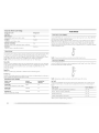
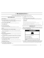
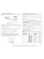
Vent system chart
NOTE: Performance of rear exhaust to either side of the dryer is equiw_lent to adding one
elbow. To determine maximum exhaust length, add one elbow to the chart.
Number of 90 ° Type of vent Box or Louvered Angled hoods
turns or elbows hoods
0 Rigid metal 64 ft (20 m) 58 ft (17.7 m)
Flexible metal 36 ft (11 m) 28 ft (8.5 m/
1 Rigid metal 54 ft (16.5 m) 48 ft (14.6 m)
Flexible metal 31 ft (9.4 m) 23 ft (7 m)
2 Rigid metal 44 ff (13.4 m) 38 ft (11.6 m)
Flexible metal 27 ff (8.2 m) 19 ft (5.8 m/
3 Rigid metal 35 ff (10.7 m) 29 ft (8.8 m)
Flexible metal 25 ff (7.6 m) 17 ft (5.2 m/
4
Rigid metal 27 ft (8.2 m) 21 ft (6.4 m)
Flexible metal 23 ft 17 m) 15 ft (4.6 m)
INSTALL VENT SYSTEM
1. install exhaust hood. Use caulking compound to seal exterior wall opening around
exhaust hood.
2. Connect vent to exhaust hood. Vent must fit inside exhaust hood. Secure vent to exhaust
hood with 4" (10.2 cm) clamp.
3. Run vent to dryer location. Use the straightest path possible. See "Determine vent path" in
"Plan Vent System." Avoid 90° turns. Use clamps to seal all joints. Do not use duct tape,
screws or other fastening devices that extend into the interior of the vent to secure vent.
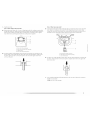
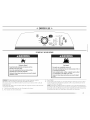
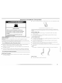
INSTALL LEVELING LEGS
Excessive Weight Hazard
Use two or more people to move and install dryer.
Failure to do so can result in back or other injury.
1. lb protect the floor, use a large, flat piece of cardboard from the dryer carton. Place
cardboard under the entire back edge of the dryer.
2. Firmly grasp the body of the dryer (not the top or console panel). Gently lay the dryer on
the cardboard. See illustration.
Examine the leveling legs. Find the diamond marking.
4. Screw the legs into the leg holes by hand. Use a wrench to finish turning the legs until the
diamond marking is no longer visible.
5. Place a carton corner post from dryer packaging under each of the 2 dryer back corners.
Stand the dryer up. Slide the dryer on the corner posts until it is close to its final location.
Leave enough room to connect the exhaust vent.

CONNECT VENT
1. Using a 4" (10.2 cm) clamp, connect vent to exhaust outlet in dryer. If connecting to
existing vent, make sure the vent is clean. The dryer vent must fit over the dryer exhaust
outlet and inside the exhaust hood. Check that the vent is secured to exhaust hood with a
4" (102 cm) clamp.
2. Move dryer into its final location. Do not crush or kink vent.
3. (On gas models) Check that there are no kinks in the flexible gas line.
4. Once the exhaust vent connection is made, remove the corner posts and cardboard.
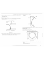
LEVEL DRYER
Check tile levelness of the dryer by first placing a level on the top of the dryer near the
console,
Then, by placing a level ill the crease on the side of the dryer between the top of the dryer and
the dryer cabinet, check the levelness from front to back.
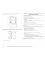
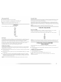
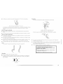
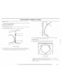
REVERSE DOOR SWING
You can change your door swing from a right-side opening to a left-side opening, if desired.
1. Place a towel or soft cloth on top of the dryer or work space to protect the surface.
Remove the door assembly
1. Open the dryer door.
2. Remove the bottom screw from each of the 2 hinges that attach the dryer door to the front
panel of the dryer.
3. [oosen the top screw from each of the 2 hinges in Step 2.
A
B
A
B
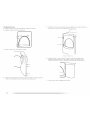
4,
A. _oosd!l} thd!s(! scF(!ws.
B. Rd!movd! t]l(!sd! 8c1(!w8.
Remove the dryer door and the hinges by lifting upward on the door. I.ay the door on a
flat, protected surface, with the inside of the door facing up. Remove remaining 2 loose
screws from dryer front paneh
If the dryer is not level, prop up the dryer using a wood block. Use a wrench to adjust the legs
up or down and check again for levelness.
18

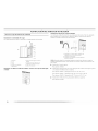
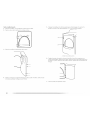
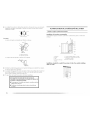
5. Removethe4plasticplugslocatedoutsidethedryerdooropening.
II
II
6. Install 4 plastic plugs into screw holes in the dryer left where the hinges were removed in
Step 4.
Reverse the strike
1. Remove the door strike from the dryer door opening.
2. Remove the cosmetic screw opposite the door strike.
A. Door strike
m. _OSITI(!tic scr_!\,v
Reinstall the door strike and cosmetic screw on the opposite side of the dryer door
opening from where they were removed.
NOTE: Door strike and plugs must be on the same side of the dryer door opening.
Reinstall the door
1. Remove the 4 screws and 2 hinges from the dryer door.
2. Replace the 4 screws in the same holes.
3. Remove the 4 screws from the opposite side of the door.
Install the 2 hinges to the front panel of the dryer using 4 screws. Use the non-slotted side
to attach the hinge to the front panel.
I

5,
6,
Install screws in the top hinge holes ill the door. Do not tighten screws. I.eave
approximately Y2'/5 mm) of screw exposed.
A. hlstall these screws first.
Hang door by placing screw heads into top slotted holes of hinges and slide door down.
Align bottom screw holes ill hinge and door. Install two bottom screws. Tighten all hinge
screws,
7. Close door to engage door strike.
COMPLETE INSTALLATION
1. Check that all parts are now installed. If there is an extra part, go back through the steps to
see which step was skipped.
2. Check that you have all of your tools.
3. Dispose of/recycle all packaging materials.
4. Check the dryer's final location. Be sure the vent is not crushed or kinked.
5. Check that the dryer is level. See "l.evel Dryer."
6. In the U.S.A.
• For power supply cord installation, plug into a grounded outlet. For direct wire
installation, turn on power.
In Canada
• Plug into a grounded 4 prong outlet, lurn on power.
7. Remove any protective film or tape remaining on the dryer.
NOTE: Class door models have a protective film on the window that should be removed.
8. Read "Dryer Use."
9. Wipe the dryer drum interior thoroughly with a damp cloth to remove any dust.
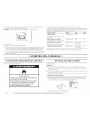
10. ]i_st dryer operation by selecting a Timed Dry heated cycle and starting the dryer. For this
test, do not select the Air Fluff modifier.
If the dryer will not start, check the following:
• Controls are set in a running or "On" position.
• Start button has been pushed firmly.
• Dryer is plugged into an outlet and/or electrical supply
is on.
• Household fuse is intact and tight, or circuit breaker has not tripped.
• Dryer door is closed.
11. When the dryer has been running for 5 minutes, open the dryer door and feel for heat. [f
you feel heat, cancel cycle and close the door.
If you do not feel heat, turn off the dryer and check the following:
• [here may be 2 household fuses or circuit breakers for the dryer. Check that both fuses
are intact and tight, or that both circuit breakers have not tripped. [f there is still no
heat, contact a qualified technician.
NOTE: You may notice an odor when the dryer is first heated. This odor is common when the
heating element is first used. lhe odor will go away.
20
La page est en cours de chargement...
La page est en cours de chargement...
La page est en cours de chargement...
La page est en cours de chargement...
La page est en cours de chargement...
La page est en cours de chargement...
La page est en cours de chargement...
La page est en cours de chargement...
La page est en cours de chargement...
La page est en cours de chargement...
La page est en cours de chargement...
La page est en cours de chargement...
La page est en cours de chargement...
La page est en cours de chargement...
La page est en cours de chargement...
La page est en cours de chargement...
La page est en cours de chargement...
La page est en cours de chargement...
La page est en cours de chargement...
La page est en cours de chargement...
La page est en cours de chargement...
La page est en cours de chargement...
La page est en cours de chargement...
La page est en cours de chargement...
La page est en cours de chargement...
La page est en cours de chargement...
La page est en cours de chargement...
La page est en cours de chargement...
La page est en cours de chargement...
La page est en cours de chargement...
La page est en cours de chargement...
La page est en cours de chargement...
La page est en cours de chargement...
La page est en cours de chargement...
La page est en cours de chargement...
La page est en cours de chargement...
La page est en cours de chargement...
La page est en cours de chargement...
La page est en cours de chargement...
La page est en cours de chargement...
La page est en cours de chargement...
La page est en cours de chargement...
La page est en cours de chargement...
La page est en cours de chargement...
La page est en cours de chargement...
La page est en cours de chargement...
La page est en cours de chargement...
La page est en cours de chargement...
La page est en cours de chargement...
La page est en cours de chargement...
La page est en cours de chargement...
La page est en cours de chargement...
La page est en cours de chargement...
La page est en cours de chargement...
La page est en cours de chargement...
La page est en cours de chargement...
La page est en cours de chargement...
La page est en cours de chargement...
La page est en cours de chargement...
La page est en cours de chargement...
La page est en cours de chargement...
La page est en cours de chargement...
La page est en cours de chargement...
La page est en cours de chargement...
La page est en cours de chargement...
La page est en cours de chargement...
La page est en cours de chargement...
La page est en cours de chargement...
-
 1
1
-
 2
2
-
 3
3
-
 4
4
-
 5
5
-
 6
6
-
 7
7
-
 8
8
-
 9
9
-
 10
10
-
 11
11
-
 12
12
-
 13
13
-
 14
14
-
 15
15
-
 16
16
-
 17
17
-
 18
18
-
 19
19
-
 20
20
-
 21
21
-
 22
22
-
 23
23
-
 24
24
-
 25
25
-
 26
26
-
 27
27
-
 28
28
-
 29
29
-
 30
30
-
 31
31
-
 32
32
-
 33
33
-
 34
34
-
 35
35
-
 36
36
-
 37
37
-
 38
38
-
 39
39
-
 40
40
-
 41
41
-
 42
42
-
 43
43
-
 44
44
-
 45
45
-
 46
46
-
 47
47
-
 48
48
-
 49
49
-
 50
50
-
 51
51
-
 52
52
-
 53
53
-
 54
54
-
 55
55
-
 56
56
-
 57
57
-
 58
58
-
 59
59
-
 60
60
-
 61
61
-
 62
62
-
 63
63
-
 64
64
-
 65
65
-
 66
66
-
 67
67
-
 68
68
-
 69
69
-
 70
70
-
 71
71
-
 72
72
-
 73
73
-
 74
74
-
 75
75
-
 76
76
-
 77
77
-
 78
78
-
 79
79
-
 80
80
-
 81
81
-
 82
82
-
 83
83
-
 84
84
-
 85
85
-
 86
86
-
 87
87
-
 88
88


Maytag MED6300TQ - 29" Front-Load Electric Dryer Mode d'emploi
- Catégorie
- Sèche-linge électriques
- Taper
- Mode d'emploi
dans d''autres langues
Documents connexes
-
Maytag MED6400TQ 7 Guide de démarrage rapide
-
Maytag MED5820TW0 Le manuel du propriétaire
-
-
-
-
-
-
-
-