
Montageanleitung
Motorvollschutzschalter
Mounting instructions
Motor protection switch
Notice de montage
Disjoncteur-protecteur intégral
MVE 10
www.maico- ventilatoren.com
DE
UK
FR

DE │ 1. Allgemeine Hinweise
2
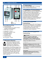
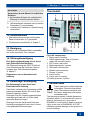
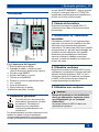
Abb. Gerätekomponenten
1 Gehäuseoberteil
2 Leitungsdurchführung, gesamt 6 Stück
(jeweils mit Sollbruchstelle)
3 AUS-Taste, rote Taste
4 Haltewinkel, 2 Stück
5 EIN-Taste, schwarze Taste
6 Spritzwasserschutz
7 Schraube, 2 Stück
8 Schaltereinsatz
9 Gehäuseunterteil
10 Leitungstülle, 2 Stück
1. Allgemeine Hinweise
Diese Anleitung enthält wichtige
Informationen. Befolgen Sie die
Anweisungen. Übergeben Sie die
Anleitung an den Eigentümer.
Diese Anleitung gut aufbewahren.
Die aufgeführten Warnhinweise zeigen Ihnen
Gefahrensituationen, die bei GEFAHR zum
Tod oder ernsten Verletzungen führen oder
bei WARNUNG zum Tod oder ernsten Ver-
letzungen führen könnten, sofern sie nicht
vermieden werden. ACHTUNG steht für
mögliche Sachschäden am Produkt oder
seiner Umgebung.
2. Lieferumfang
Motorvollschutzschalter MVE 10, 2 Leitungs-
tüllen und diese Montageanleitung.
3. Qualifikation Fachinstallateur
Der MVE 10 darf nur von einer Elektrofachkraft
entsprechend dieser Anleitung installiert
werden. Sie sind eine Elektrofachkraft, wenn
Sie aufgrund Ihrer fachlichen Ausbildung,
Schulung und Erfahrung die elektrischen
Anschlüsse gemäß Verdrahtungsplan
fachgerecht und sicher ausführen können und
Risiken und Gefährdungen durch Elektrizität
erkennen und vermeiden können.
4. Bestimmungsgemäße
Verwendung
Motorvollschutzschalter MVE 10 für Einphasen-
Wechselstrom-Ventilatoren mit ausgeführten
Thermokontakten. MVE 10 mit Hauptschütz
und Steuersicherung. Der MVE 10 ist
ausschließlich für den häuslichen Gebrauch
und ähnliche Zwecke vorgesehen.
5. Nicht bestimmungsgemäße
Verwendung
GEFAHR
Explosionsgefahr bei Betrieb in
explosionsfähiger Atmosphäre bei
Entzündung (z. B. bei Funkenbildung).
Den MVE 10 auf keinen Fall in explosions-
fähiger Atmosphäre einsetzen.
ACHTUNG
Gerätebeschädigung durch An- oder
Umbauten. Veränderungen und Umbauten
am Gerät sind nicht zulässig und entbinden
den Hersteller von jeglicher Gewährleistung
und Haftung.
ACHTUNG
Gerätebeschädigung bei Einsatz in
Außenbereichen. MVE 10 nur in Innen-
bereichen einsetzen.

6. Sicherheitshinweise │ DE
3
6. Sicherheitshinweise
WARNUNG
Gefahren für Personen (auch
Kinder) mit eingeschränkten
physischen, sensorischen
oder psychischen Fähigkei-
ten oder mangelndem Wissen.
MVE 10 nur von Personen in-
stallieren, in Betrieb nehmen,
reinigen und warten lassen,
welche die Gefahren dieser
Arbeiten sicher erkennen und
vermeiden können.
GEFAHR
Gefahr durch elektrischen
Schlag. Vor Zugang zu den
Anschlussklemmen:
alle Versorgungsstromkreise
freischalten,
benachbarte, unter Spannung
stehende Teile abdecken
oder abschranken,
gegen Wiedereinschalten
sichern und
Spannungsfreiheit prüfen.
WARNUNG
Gefahr durch automatisch
anlaufenden Ventilator nach
einem Stromausfall.
MVE 10 reagiert auf Über-
hitzung, z. B. bei Über-
spannung.
Bei Arbeiten im Gefahren-
bereich des Ventilators ist der
Ventilator zusätzlich vom
Netz zu trennen, generell bei
Installations-, Reinigungs-,
Wartungs- und Reparatur-
arbeiten.
7. Funktion/Bedienung
Der MVE 10 schützt den Ventilatormotor vor
Überspannung/Überhitzung. Wird die
zulässige Temperatur in der Motorwicklung
(Steuerstromkreis Thermokontakte TK)
überschritten, fällt der MVE-Hauptschütz ab
und trennt den Motor vom Netz.
Verhalten bei ausgelöstem Hauptschütz
Nach dem Abkühlen der Motorwicklung (je
nach Ventilator bis zu 30 Minuten) verhindert
eine Wiedereinschaltsperre im MVE 10 das
selbsttätige Einschalten des Motors.
Zum Wiedereinschalten zuerst die rote Taste
„0“ und dann die schwarze Taste „1“ drücken,
so dass Taste „1“ einrastet.
Wird der Ventilator eingeschaltet bevor der
Motor abgekühlt ist, erfolgt innerhalb von
60 Sekunden eine erneute Auslösung.

DE │ 8. Technische Daten
4
8. Technische Daten
Typenschild auf dem Gerät.
Bemessungsspannung
230 V AC
Netzfrequenz 50/60 Hz
Maximalbelastung
(induktive Last)
0,4 A
Maximalbelastung
(ohmsche Last)
10 A
Funkentstörung
(EN 55011)
VDE 0875,
Störgrad N
Schutzart
IP 54
Schutzklasse
II
Einbauart Aufputz
Gewicht
0,5 kg
Maße (B x H x T)
75 x 140 x 95 mm
9. Umgebungsbedingungen und
Grenzen für den Betrieb
Zulässige Umgebungstemperatur max. +50 °C
10. Lagerung
Gerät nur trocken lagern (-20 bis +50 °C).
11. Montage
11.1 Montagehinweise
● Gerät nur auf trockenem, ebenen Unter-
grund montieren. Einbaulage beliebig.
● Gerät nur komplett montiert betreiben.
● Gerät nur an einer fest verlegten
elektrischen Installation anschließen.
● Gerät nur mit auf dem Typenschild
angegebener Spannung und Frequenz
betreiben.
● Bei der Elektroinstallation die geltenden
Vorschriften beachten, in Deutschland
insbesondere VDE 0100 mit den
entsprechenden Teilen.
● Eine Vorrichtung zur Trennung vom Netz
mit mindestens 3 mm Kontaktöffnung je
Pol ist vorgeschrieben.
● Schutzart nur gewährleistet bei bestim-
mungsgemäßem Einbau und ordnungs-
gemäßer Einführung der Leitungen in das
Gehäuse.
11.2 Gerätemontage
1. Versorgungsstromkreise abschalten, Warn-
schild gegen Wiedereinschalten sichtbar
anbringen, Spannungsfreiheit prüfen.
2. Beide Schrauben des Gehäusedeckels
lösen, Gehäusedeckel abnehmen.
3. Beide Halterungen [4] abziehen und den
Schaltereinsatz [8] aus dem Gehäuse
nehmen.
4. Im Gehäuseunterteil einen der Leitungs-
durchbrüche kreisrund herausschneiden
(an der Sollbruchstelle).
ACHTUNG
Kurzschluss durch Nässe bei nicht
ordnungsgemäßem Einsetzen der
Tülle(n) oder falscher Einführung der
Anschlussleitungen in das Gehäuse.
Tüllen so einsetzen, dass diese dicht am
Gehäuse anliegen und die Leitungen
dicht umschließen.
5. Bei Aufputzzuführung der Anschlusslei-
tung mitgelieferte Tülle(n) [10] bis an den
Bund in das Gehäuseunterteil einsetzen.
Darauf achten, dass die Tülle dicht am
Gehäuse anliegt.
6. Gehäuseunterteil an der Wand befestigen.
Geeignetes Befestigungsmaterial ist
bauseitig bereitzustellen.
7. Anschlussleitung in das Gehäuse führen.
Bei Aufputzanschluss muss die mitge-
lieferte Leitungstülle [10] eingesetzt und
die Dichtigkeit geprüft sein.
8. Motorvollschutzschalter gemäß Schaltbild
( Kapitel 16) verdrahten. Verdrahtung
prüfen, Schrauben der Anschlussklemmen
ggf. nachziehen.
9. Schaltereinsatz [8] in das Gehäuseunter-
teil einsetzen.
10. Beide Halterungen [4] in das Gehäuse
einsetzen und nach ganz nach unten
drücken.

11. Montage / 1. General notes │ DE/UK
5
ACHTUNG
Kurzschluss durch Nässe bei undichtem
Gehäuse.
Auf korrekten Einsatz der umlaufenden
Dichtung im Gehäuseoberteil achten.
11. Gehäuseoberteil aufsetzen und mit beiden
Schrauben [7] verschrauben.
12. Ventilator(en) installieren. Netzsicherung
einschalten.
12. Inbetriebnahme
1. Übereinstimmung mit den technischen
Daten kontrollieren Typenschild.
2. Funktionstest durchführen Kapitel 7.
13. Reinigung
Gehäuse und Temperaturfühler regelmäßig
mit einem trockenen Tuch reinigen.
14. Störungsbeseitigung
Eine Störungsbeseitigung ist nur durch
eine Elektrofachkraft zulässig.
Die Steuersicherung des MVE 10 löst bei
einer Überhitzung der Ventilator-Thermo-
kontakte aus. Zum Wiedereinschalten
Kapitel 7.
Reparaturen nur im Herstellerwerk
zulässig.
15. Demontage, Entsorgung
Die Demontage ist nur durch eine
Elektrofachkraft zulässig.
Das Gerät und auch die Verpackung enthält
wiederverwertbare Stoffe, die nicht in den
Restmüll gelangen dürfen.
Entsorgen Sie die Verpackungsmaterialien
umweltgerecht nach den in Ihrem Land
geltenden Bestimmungen.
Entsorgen Sie das Gerät nach Ende der
Nutzung umweltgerecht nach den in Ihrem
Land geltenden Bestimmungen.
Thermostat
Fig. Unit components
1 Upper part of housing
2 Cable lead-through, total of 6 pieces
(each with knockout point)
3 OFF button, red button
4 Retaining bracket, 2 pieces
5 ON button, black button
6 Splash water protection
7 Screws, 2 pieces
8 Switch insert
9 Lower part of housing
10 Cable grommet, 2 pieces
1. General notes
These instructions contain important
information. Follow the instructions
given. Pass these instructions onto
the owner. Keep these instructions
somewhere safe.
The warnings provided, indicate hazardous
situations which, if not avoided will result in
death or serious injury in the case of
DANGER or could result in death or serious
injury in the case of WARNING. NOTICE
indicates potential damage to the product or
its surroundings.

UK │ 6. Safety instructions
6
2. Scope of delivery
MVE 10 motor protection switch, 2 cable
grommets and these mounting instructions.
3. Specialist installer qualification
The MVE 10 may only be installed by a
trained electrician, in line with these
instructions. You are deemed competent if
you can competently and safely connect units
to an electrical power supply in line with the
wiring diagram, on the basis of your technical
training and experience and are able to
recognise and avoid risks and dangers
associated with electricity.
4. Intended use
MVE 10 motor protection switch for single-
phase
AC fans with fitted thermal contacts. MVE 10
with main contactor and control fuse. The
MVE 10 is only intended for domestic use
and similar purposes.
5. Non-intended use
DANGER
Explosion hazard if operated in an
explosive atmosphere in the case of
ignition, e.g. from sparks.
The MVE 10 should never be deployed in
potentially explosive atmospheres.
NOTICE
Unit damage through modifications and
alterations. Modifications and alterations to
the unit are not permitted and release the
manufacturer from any guarantee and
liability.
NOTICE
Damage to the unit when used
outdoors. The MVE 10 should only be
deployed indoors.
6. Safety instructions
WARNING
Risks for people (including
children) with reduced
physical, sensory or mental
capabilities or a lack of
knowledge.
The MVE 10 may only be
installed, commissioned,
cleaned and maintained by
people who can safely
recognise and avoid the risks
associated with this work.
DANGER
Danger from electric shock.
Before accessing the
connection terminals:
Switch off all supply circuits.
Cover or block off neigh-
bouring live components.
Protect against being acci-
dentally switched back on.
Check that there is in fact no
voltage present.

6. Safety instructions │ UK
7
WARNING
Danger from automatic
startup of fan following a
power failure.
The MVE 10 reacts to over-
heating, e.g. caused by
over-voltage.
In the case of work including
installation, cleaning,
maintenance and repair work
in the danger area of the fan,
the fan should additionally be
separated from the mains
power supply.
7. Function/Operation
The MVE 10 protects the fan motor against
over-voltage/overheating. If the permitted
temperature in the motor winding (TK thermal
contact control circuit) is exceeded, the
MVE motor winding drops out and separates
the motor from the mains power supply.
Procedure in the case of a triggered main
contactor
After the motor winding has cooled down,
which can take up to 30 minutes depending
on the fan, a restart interlock in the MVE10
prevents the automatic switch-on of the
motor.
In order to trigger a restart, first press the red
button “0” and then the black button “1” so
that button “1” locks into place.
If the fan is switched back on before the
motor has cooled down, the MVE 10 is
triggered again within 60 seconds.
8. Technical data
Rating plate on the unit.
Rated voltage
230 VAC
Power frequency
50/60 Hz
Maximum load
(inductive load)
0.4 A
Maximum load
(ohmic load)
10 A
Radio interference
suppression
DIN EN 55011
VDE 0875
Interference
level N
Degree of protection
IP 54
Protection class
II
Type of installation
Surface-mounted
Weight
0.5 kg
Dimensions (W x H x D)
75 x 140 x 95 mm
9. Environmental conditions and
operating limits
Permitted max. ambient temperature: +50 ℃
10. Storage
Store unit exclusively in a dry location (-20 to
+50 °C).
11. Mounting
11.1 Mounting instructions
● Only install unit on a dry, level surface. Any
installation position can be selected.
● Only operate the unit when it is completely
installed.
● Only connect unit to a permanently wired
electrical installation.
● The unit may only be operated using the
voltage and frequency shown on the rating
plate.
● Be sure to observe the relevant regulations
for electrical installation; in Germany this is
particularly VDE 0100, with the corres-
pondding parts.

UK │ 11. Mounting
8
● A mains isolation device with contact
openings of at least 3 mm at each pole is
mandatory.
● The degree of protection is only
guaranteed if installation is undertaken
correctly and if the cables are correctly fed
into the housing.
11.2 Unit mounting
1. Switch-off the mains power supply, position
a visible warning notice to avoid the unit
being accidentally switched back on, check
that there is in fact no voltage present.
2. Loosen both of the housing cover screws
and remove the housing cover.
3. Pull off both retaining brackets [4] and
take the switch insert [8] out of the
housing.
4. Make a circular cutout in one of the cable
breakthroughs, at the knockout point.
NOTICE
Danger of short-circuits caused by
damp if the grommet(s) are not correctly
inserted or if the connection cables are
not fed into the housing correctly.
Insert the grommets so that they fit tightly
against the housing and around the cables.
5. If the connection cable is surface-
mounted, insert the supplied grommet(s)
[10] right up to the join in the lower part of
the housing. Make sure that grommet fits
tightly against the housing.
6. Mount the lower part of the housing on the
wall. Suitable mounting material is to be
supplied by the customer.
7. Feed the connection cable into the
housing. If the connection cable is
surface-mounted, the supplied grommet
[10] must be used and the tightness of the
fit must be checked.
8. Connect up the motor protection switch
as shown in the wiring diagram (
Chapter 16). Check the wiring and if
necessary, tighten the screws in the
connection terminals.
9. Locate the switch insert [8] into the lower
part of the housing.
10. Insert both retaining brackets in the
housing [4] and push them down all the
way.
NOTICE
Danger of short-circuits caused by damp
if the housing is not fully sealed.
Make sure the wrap-around seal is correctly
located in the upper part of the housing.
11. Fit upper part of housing and secure with
both screws [7].
12. Install the fan(s). Switch the mains fuse on.
12. Start-up
1. Check that the technical data has been
adhered to rating plate.
2. Carry out a function test Chapter 7.
13. Cleaning
Clean the housing and the temperature sensor
regularly using a dry cloth.
14. Fault rectification
Fault rectification should only be carried
out by a trained electrician.
The MVE 10’s control fuse triggers if the fan
thermal contact overheats. To switch back on
Chapter 7. Repairs may only be carried
out at the manufacturer’s factory.
15. Dismantling and disposal
Dismantling should only be carried out by
a trained electrician.
The unit and the packaging contain parts that
can be recycled, and should not end up in the
domestic waste.
Dispose of the packaging material in an
environmentally-friendly way, in compliance
with the regulations valid in the country where
you are.
At the end of its service life, dispose of the
unit in an environmentally-friendly way, in
compliance with the regulations valid in the
country of use.

1. Remarques générales │ FR
9
Thermostat
Fig. Composants de l'appareil
1 Partie supérieure du boîtier
2 Passage de câble, 6 unités au total
(chacun avec point destiné à la rupture)
3 Touche rouge ARRÊT
4 Équerre de fixation, 2 unités
5 Touche noire MARCHE
6 Protection contre les projections d'eau
7 Vis, 2 unités
8 Insert d'interrupteur
9 Partie inférieure du boîtier
10 Manchon de câble, 2 unités
1. Remarques générales
Ces instructions contiennent des
informations importantes. Veuillez
les observer. Remettez les
instructions au propriétaire.
Conservez précieusement ces
instructions.
Les avertissements qu'elles contiennent vous
mettent en garde contre les situations
dangereuses susceptibles d'entraîner la mort
en cas de DANGER ou de graves blessures
en cas d'AVERTISSEMENT, dans la mesure
où elles ne sont pas évitées. ATTENTION
signale des endommagements possibles du
produit ou de son environnement.
2. Volume de fourniture
Disjoncteur-protecteur intégral MVE 10,
2 manchons de câble et la présente notice
de montage.
3. Qualification de l'installateur
spécialisé
L'installation du MVE 10 est exclusivement
réservée à un électricien qualifié et doit être
effectuée conformément aux présentes
instructions. On entend par électricien qualifié
une personne qui, par son apprentissage, sa
formation et son expérience, est capable
d'exécuter les branchements électriques
selon le schéma de câblage et en toute
sécurité, connaît les dangers de l'électricité
et peut les éviter.
4. Utilisation conforme
Disjoncteur-protecteur intégral MVE 10 pour
ventilateurs monophasés à courant alternatif
équipés de thermocontacts. MVE 10 avec
contacteur général et fusible de commande.
Le MVE 10 est exclusivement réservé à
l'usage domestique et similaires.
5. Utilisation non conforme
DANGER
Risque d'explosion en cas d'utilisation
dans une atmosphère explosive suite à
une inflammation (p. ex. formation
d'étincelles).
Ne jamais utiliser le MVE 10 dans une
atmosphère explosive.

FR │ 6. Consignes de sécurité
10
ATTENTION
Endommagement de l'appareil suite à
modifications ou transformations. Les
modifications et transformations apportées
sur l'appareil sont rigoureusement interdites
et dégagent le fabricant de toute
responsabilité et garantie.
ATTENTION
Endommagement de l'appareil en cas
d'utilisation à l'extérieur. Utiliser le
MVE 10 exclusivement à l'intérieur.
6. Consignes de sécurité
AVERTISSEMENT
Danger pour les personnes
(y compris les enfants) ayant
des capacités physiques,
sensorielles ou psychiques
réduites ou sans
connaissances suffisantes.
L'installation, la mise en
service, le nettoyage et
l'entretien du MVE 10 ne
pourront être effectués que
par des personnes
conscientes des risques
présentés par ces travaux
et en mesure de les éviter.
DANGER
Risque d'électrocution.
Avant d'accéder aux bornes
de raccordement :
couper tous les circuits
d'alimentation électrique,
recouvrir ou isoler les pièces
adjacentes sous tension,
protéger contre une remise
en marche inopinée et
contrôler l'absence de
tension.
AVERTISSEMENT
Danger dû à la remise en
marche automatique du
ventilateur après une panne
de courant.
Le MVE 10 réagit à la
surchauffe, par ex. en cas de
surtension.
Pour travailler dans le
périmètre dangereux du
ventilateur, couper le
ventilateur du secteur comme
c'est toujours le cas lors des
travaux d'installation, de
nettoyage, d'entretien et de
réparation.

8. Caractéristiques techniques │ FR
11
7. Fonctionnement / Commande
Le MVE 10 protège le moteur du ventilateur
de la surtension/surchauffe. Si la température
admissible est dépassée dans la bobine de
moteur (circuit de courant de commande,
thermocontacts TK), le contacteur général
MVE retombe et coupe le moteur du secteur.
Comportement face à un contacteur
général déclenché
Après le refroidissement de la bobine de
moteur (jusqu'à 30 minutes en fonction du
ventilateur), le verrouillage au réenclenche-
ment du MVE 10 prévient le redémarrage
automatique du moteur.
Pour la remise en marche, appuyer en
premier lieu sur la touche rouge « 0 », puis
sur la touche noire « 1 » de manière à ce
que la touche « 1 » s'enclenche.
Si le ventilateur est allumé avant le refroi-
dissement du moteur, le ventilateur se
déclenche à nouveau après 60 secondes.
8. Caractéristiques techniques
Plaque signalétique sur l'appareil.
Tension de service
230 V CA
Fréquence du secteur
50/60 Hz
Charge maximale
(charge inductive)
0,4 A
Charge maximale
(charge ohmique)
10 A
Antiparasitage
(EN 55011)
VDE 0875, degré
de parasitage N
Type de protection
IP 54
Classe de protection II
Type de montage
Montage apparent
Poids
0,5 kg
Dimensions (l x h x p)
75 x 140 x 95 mm
9. Conditions ambiantes et limites
d'utilisation
Température ambiante max. autorisée +50°C
10. Stockage
Stockage uniquement dans un endroit sec
(de -20 à +50 °C).
11. Montage
11.1 Consignes de montage
● Monter l'appareil exclusivement sur une
base sèche et plane. Position d'installation
au choix.
● N'utiliser l'appareil qu'après son montage
complet.
● Raccorder l'appareil uniquement à une
installation électrique permanente.
● L'appareil ne doit fonctionner qu'à la
tension et à la fréquence indiquées sur la
plaque signalétique.
● La réglementation en vigueur pour
l'installation électrique et notamment, pour
l'Allemagne, la norme DIN VDE 0100 et
les parties correspondantes, doivent être
respectées.
● Prévoir un dispositif de coupure du
secteur avec une ouverture de contact
d'au moins 3 mm par pôle.
● Le type de protection n'est assuré que si
le montage est effectué selon les
instructions et si les câbles ont été
introduits correctement dans le boîtier.
11.2 Montage de l'appareil
1. Couper les circuits d'alimentation
électrique, apposer un panneau
d'avertissement de manière bien visible
pour prévenir toute remise en service
intempestive, contrôler l'absence de
tension.
2. Desserrer les deux vis du couvercle de
boîtier et déposer le couvercle de boîtier.
3. Retirer les deux fixations [4] et sortir
l'insert d'interrupteur [8] du boîtier.
4. Découper une ouverture circulaire dans
l'un des passages de câble à la partie
inférieure du boîtier (au point de rupture).

FR │ 11. Montage
12
ATTENTION
Court-circuit provoqué par l'humidité en
cas d'insertion incorrecte du/des
manchon(s) ou introduction erronée des
câbles de raccordement dans le boîtier.
Fixer les manchons de sorte qu'ils soient
bien appliqués sur le boîtier et enserrent
fermement les câbles.
5. Pour la pose apparente du câble de
raccordement, introduire le/les
manchon(s) fourni(s) [10] dans la partie
inférieure du boîtier jusqu'au collet. Veiller
à ce que le manchon soit bien appliqué
sur le boîtier.
6. Fixer la partie inférieure du boîtier au mur.
Le matériel de fixation adéquat est à
fournir par le client.
7. Introduire le câble de raccordement dans
le boîtier. Pour le raccordement électrique
apparent, utiliser le manchon fourni [10] et
contrôler l'étanchéité.
8. Connecter le disjoncteur-protecteur
intégral selon le schéma de branchement
( Chapitre 16). Contrôler le câblage,
resserrer les vis des bornes de
raccordement si besoin est.
9. Introduire l'insert d'interrupteur [8] dans la
partie inférieure du boîtier.
10. Introduire les deux fixations [4] dans le
boîtier et enfoncer à fond vers le bas.
ATTENTION
Court-circuit provoqué par l'humidité si
le boîtier n'est pas étanche.
Veiller au positionnement correct du joint
sur tout le pourtour de la partie
supérieure du boîtier.
11. Poser la partie supérieure du boîtier et la
fixer à l'aide des deux vis [7].
12. Installer le(s) ventilateur(s). Activer le
fusible secteur.
12. Mise en service
1. Contrôler la concordance avec les
caractéristiques techniques plaque
signalétique.
2. Effectuer un test de fonctionnement
Chapitre 7.
13. Nettoyage
Nettoyer régulièrement le boîtier et la sonde
de température avec un chiffon sec.
14. Suppression de
dysfonctionnements
La suppression d'un dysfonctionnement
doit exclusivement être effectuée par un
électricien.
En cas de surchauffe, le fusible de commande
du MVE 10 déclenche les thermocontacts du
ventilateur. Pour remettre en marche
Chapitre 7.
Réparations exclusivement réservées à
l'usine du constructeur.
15. Démontage, élimination
Le démontage doit exclusivement être
effectué par un électricien.
L'appareil, ainsi que son emballage, contient
des matériaux recyclables qui ne doivent pas
être éliminés avec les ordures ménagères.
Éliminez les matériaux d'emballage dans le
respect de l'environnement, conformément
aux prescriptions locales.
Éliminez l'appareil hors d'usage dans le
respect de l'environnement, conformément
aux prescriptions en vigueur dans votre pays.

16. Schaltbilder, Wiring diagrams, Schémas de branchement │ FR/UK/DE
13
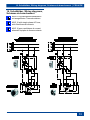
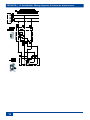
16. Schaltbilder, Wiring diagrams,
Schémas de branchement
MVE 10 für Wechselstromventilatoren
mit ausgeführten Thermokontakten.
MVE 10 with single-phase AC fans,
with fitted thermal contacts.
MVE 10 pour ventilateurs à courant
alternatif équipés de thermocontacts.

DE/UK/FR │ 16. Schaltbilder, Wiring diagrams, Schémas de branchement
14

15

de │ gb
Maico Elektroapparate-Fabrik GmbH • Steinbeisstr. 20 • 78056 Villingen-Schwenningen •
Germany • Service +49 7720 6940 • technik@maico.de
07.16_Es
0185.0828.0004_RLF.6_07.16_DSW
-
 1
1
-
 2
2
-
 3
3
-
 4
4
-
 5
5
-
 6
6
-
 7
7
-
 8
8
-
 9
9
-
 10
10
-
 11
11
-
 12
12
-
 13
13
-
 14
14
-
 15
15
-
 16
16


dans d''autres langues
- English: Maico MVE 10
- Deutsch: Maico MVE 10
Documents connexes
-
Maico EZR 30/6 B Mounting And Operating Instructions
-
-
Maico EDR 31 Mounting And Operating Instructions
-
Maico EZD BL Series Operating Instructions Manual
-
-
-
-