Yamaha Outboards 703 Mode d'emploi
- Catégorie
- Moteur
- Taper
- Mode d'emploi
La page est en cours de chargement...
La page est en cours de chargement...

NOTICE
This remote control box is so designed that both clutch and
throttle can be actuated by operating the remote control
lever. For the correct operation and installation of the
remote control box, please read this manual carefully and
thoroughly.
Particularly important information is distinguished in this
manual by the following notations.
A
The Safety Alert Symbol means ATTENTION!
BECOME ALERT! YOUR SAFETY IS INVOLVED!
AWARNING
Failure to follow WARNING instructions could result
in severe injuly or death to the machine operator, a
bystander, or a person inspecting or repairing the re-
mote control box.
HMHi
A CAUTION indicates special precautions that must be
taken to avoid damage to the remote control box.
NOTE:
A NOTE provides key information to make procedures easi-
er or clearer.
Specifications given in this manual may be subject to
change without notice.
AVIS
Ce boitier de commande a distance est con<?u de maniere
telle que l'inversion et l'acceleration peuvent etre activees
en actionnant le levier de commande a distance. Pour
1'utilisation et le montage corrects du boitier de commande
a distance, veuillez lire ce manuel soigneusement et en
totalite.
Dans ce manuel, les informations particulierement impor-
tantes sont distinguees par les notations suivantes:
Ce symbole signale un danger et signifie:
/K ATTENTION DANGER! SOYEZ ATTENTIF!
VOTRE SECURITE EST EN JEU!
AAVERTISSEMENT
Le respect des consignes AVERTISSEMENT est imperatif,
faute de quoi le conducteur, toute personne se trouvant a
proximite ou le personnel charge de Pentretien commande
a distance risquerait d'etre grievement voire mortellement
blesse.
ATTjEMTI©§§
ATTENTION indique les consignes qui doivent etre respec-
tees afin d'eviter d'endommager le systeme de commande a
distance.
N.B.:
N.B. donne des informations importantes qui facilitent et
expliquent les differentes operations.
Les caracteristiques donnees dans ce manuel peuvent etre
changees sans avis prealable.
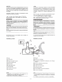
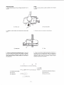
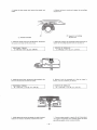
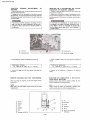
NOMENCLATURE
NOMENCLATURE
© Grip
(2) Lock button
(3) Power trim and tilt switch
(4) Neutral throttle lever
(5) Main switch
(6) Engine stop switch
(7) Wire harness
(8) Throttle friction screw
(9) Control lever
(T) Poignee
(2) Bouton de verrouillage
(3) Interrupteur de dispositif d'inclinaison et de relevage
assistes
(?) Levier d'acceleration au point mort
(5) Contacteur principal
(6) Coupe-circuit de securite
(7) Faisceau electrique
(8) Vis de reglage de friction d'acceleration
(9) Levier de commande
NOTE:
• Depending on the specification, some models are not
equipped with the power trim and tilt switch.
• Type without choke switch is available.
N.B.:
• Suivant la specification, certains modeles ne sont pas munis
de l'interrupteur de dispositif d'inclinaison et de relevage
assistes.
® Le modele sans interrupteur de starter est disponible.
-1-

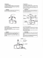
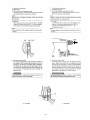
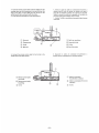
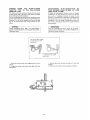
OPERATION
1. Forward and Reverse
To shift into forward and reverse, turn the control lever
downward about 32° (detent position) to the F side and R
side, respectively. When the control lever is further turned
downward, the throttle opens.
r— CAUTION
If the lock button is not fully pulled up, the control lever
will not turn further from the neutral position.
UTILISATION
1. Marche Avant et Marche Arriere
Pour enclencher la marche avant ou la marche arriere,
tourner respectivement le levier de commande vers le bas
d'environ 32° (position de detente) vers le cote F ou R.
Quand le levier de commande est tourne davantage vers le
bas, l'accelerateur s'ouvre.
— ATjm^mt
Si le bouton de verrouillage n'est pas completement tire
vers le haut, le levier de commande ne pourra pas etre
tourne au dela du point mort.
Forward
Shift
.
Marche avant Inversion
^32°
z Full-closed
Throttle Fermeture
Acceleration
Neutral
Point mort
IS| Shift Reverse
Inversion Marche
Full-closed XX
e
ation
Full-open
Ouverture
maxim ale
Ouverture
maximale
2. Free-Accelerator
Place the control lever in the neutral (N) and turn the
neutral throttle lever upward, the throttle can be opened
without shifting into any gear.
Use the neutral throttle lever when starting or warming up
the engine.
r- CAUTION:
Only when the control lever in the neutral position, the
neutral throttle lever can be operated. Without return-
ing the neutral throttle lever in the closed-position (in a
horizontal position), the control lever cannot be
operated.
2. Levier de Libre Acceleration
Mettre le levier de commande au point mort (N) et tourner
le levier d'acceleration au point mort vers le haut;
l'accelerateur peut etre ouvert sans enclencher la marche
avant ou la marche arriere.
Utiliser le levier d'acceleration au point mort pour demarrer
ou faire chauffer le moteur.
— ^rimmm^
Le levier deceleration au point mort ne peut etre
actionne que lorsque le levier de commande est au point
mort.
De plus, le levier de commande ne peut pas etre actionne
sans remettre le levier d'acceleration au point mort en
position de fermeture (levier horizontal).
Full-open
Ouverture maximale
-2-

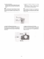
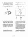
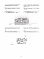
3. Operation of Switches
1) Main switch
(1)-1 Electrical circuits starting engine
By turning the key, the electrical circuit can be opened
and closed, and the engine can be started.
NOTE:
When the key is released at START, it will return to ON
automatically.
(1)-2 Choke
When pressing in the main switch at "ON" or "START"
position as shown by the arrow "—" in the illustration
to the right, the remote choke system will operate.
NOTE:
• Some models are not equipped with the remote choke
system.
3. Utilisation des Interrupteurs
1) Contacteur principal
(1)-1 Circuits electriques-demarrage du moteur
En toumant la cle, le circuit electrique peut etre ouvert et
ferme, et le moteur peut etre demarre.
N.B.:
Quand on relache la cle de la position START, elle revient
automatiquement sur la position ON.
(l)-2 Starter
Le systeme de starter a distance est actionne lorsque vous
enfoncez le contacteur principal en position "ON" ou
"START"comme indique par la fleche "—dans
illustration de droite.
N.B.:
• Certains modeles ne sont pas equipes du systeme de starter a
distance.
OFF ON START
\
ewttfiewcY •
FT
OP SW.
RUN
—<§)
, ON
RD4-
I
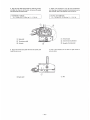
2) Emergency stop switch
The emergency stop switch is provided for the safety of
the operator. When the lock plate is pulled out from the
emergency stop switch, the engine stops immediately.
The engine will not start when the lock plate is remov-
ed. Should the operator fall off the boat or lean too far
over one side, the lock plate will pull out causing the
engine to stop.
2) Coupe-circuit de securite
Ce coupe-circuit est prevu pour la securite de l'utili-
sateur. Quand la fourchette de verrouillage est enlevee
du coupe-circuit de securite, le moteur s'arrete immedia-
tement. Quand la fourchette est enlevee, le moteur ne
peut pas etre demarre. Si l'utilisateur tombe du bateau
ou se penche trop d'un cote, la fourchette de verrouil-
lage s'enleve et entraine ainsi 1'arret du moteur.
WARNING:
When starting or operating the engine, be sure to
tie the Sock plate cord to your body.
AVERTISSEMENT:
Quand on demarre ou utilise le moteur, ne pas oublier
de s'attacher la ficelle de la fourchette au corps.
(T) Lock plate
(T) Fourchette

3) Power trim and tilt switch
The power trim and tilt switch is attached to the control
lever grip. Pushing it up trims up and tilts up the engine,
and pushing it down trims down and tilts down the
engine.
NOTE:
While the switch button is being pressed, the trim/tilt
motor turns and adjusts the engine mounting angle. When
the switch button is released, the engine will stop in its
position.
3) Interrupteur de dispositif d'inclinaison et de relevage
assistes
Cet interrupteur est integre a la poignee du levier de
commande a distance. L'appui sur le haut fait monter le
moteur, et l'appui sur le bas le fait descendre.
N.B.:
Quand on appuie sur le bouton de cet interrupteur, le
moteur d'inclinaison/de relevage tourne et regie l'angle de
fixation du moteur hors-bord. Quand on relache le bouton,
le moteur s'arrete.
4. Adjusting the Stiffness of the Control Lever
By turning in or out the throttle friction screw at the front of
the remote control box, the stiffness of the control lever
can be adjusted. Turning the screw to the right makes the
control lever stiff to turn, and turning it to the left makes
the lever light.
4. Reglage de la Durete du Levier de Commande
La durete du levier de commande peut etre reglee en vissant
ou devissant la vis de friction d'acceleration. La rotation de
la vis vers la droite rend le levier de commande dur a
tourner, et la rotation de cette vis vers la gauche adoucit la
rotation du dit levier.
\w
Make light
Pour adoucir
Make stiff
Pour doucir
—4—

5. Overheat Warning Buzzer
The sensor installed on the engine side causes the overheat
warning buzzer to sound when the engine is going to
overheat.
AWARNING
Should the overheat warning buzzer sound, turn in
the throttle grip immediately to slow down the
engine to idling speed so that it cools down. Then,
sail direct to your nearest port at low speeds.
5. Vibreur de Signalisation de Surchauffe
La sonde situee sur le moteur fait retentir le vibreur de
signalisation de surchauffe quand le moteur est sur le point
de surchauffer.
A AVERT1SSEMENT
Si le vibreur de signalisation de surchauffe retentit,
fermer immediatement la poignee d'acceleration pour
faire tourner le moteur au ralenti et lui permettre ainsi
de refroidir. Ensuite, rentrer directement au port le plus
proche a faible vitesse.
NOTE: NoB.:
Type without overheat warning buzzer is available. Le modele sans signal sonore de surchauffe est disponible.
6. Neutral Switch
The neutral switch keeps the engine from starting with
gears are shifted in. When the control lever is in Forward or
Reverse, the engine cannot be started by operating the
main switch.
6. Contacteur de Point Mort
Le contacteur de point mort empeche le moteur de
demarrer quand la marche avant ou la marche arriere est
enclenchee. Quand le levier de commande est en marche
avant ou en marche arriere, le moteur ne peut pas etre
demarre en actionnant le contacteur principal.
(T) Overheat warning
buzzer
(J) Vibreur de signalisation
de surchauffe
(T) Neutral switch
(T) Contacteur de point mort
-5-

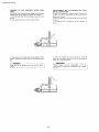
REMOTE CONTROL BOX POSITIONING
AND CABLE LENGTH
POSITIONNEMENT DU BOITIER DE COM-
MANDE A DISTANCE ET LONGUEUR DES
CABLES
AWARNING
Incorrect selection or installation of a remote con-
trol may result in sudden and unexpected loss of
control, thus resulting in a serious accident.
Please consult your Yamaha dealer.
A AVERTISSEMENT
Un mauvais choix de commande a distance ou une
mauvaise installation peuvent se traduire par une perte
de contrdle soudaine et fortuite, entrainant ainsi un
accident grave. Veuillez done consulter votre distribu-
teur Yamaha.
1. Remote Control Box Position
The remote control box should be set in a position in which
it does not obstruct the operations of the control lever and
switches. Make sure there is no obstruction on the path of
the remote control cables.
2. Remote Control Cable Length
Measure the distance from the ©point (the center of the
remote control box) to the © point (the center of the
engine) through the(B)point (a corner of the transom). Add
300 mm (1 foot) to this distance. The cable length should
be equal to the sum. Position the remote control cables and
check if they are long enough. Connect the cables to the
engine and make sure they do not get tangled or bent when
the steering wheel is turned.
— CAUTION:
Avoid bending the cables sharply; that is, make sure the
cables do not from a loop with a diameter of less than
406mm (16in).
1. Position du Boitier de Commande a Distance
Le boitier de commande a distance doit etre mis dans un
endroit ou il ne gene pas Putilisation du levier de commande
et des interrupteurs. S'assurer qu'il n'y a pas d'obstacle sur
le trajet des cables de commande a distance.
2. Longueur des Cables de Commande a Distance
Mesurer la distance du point (§) (centre du boitier de
commande a distance) au point © (centre du moteur) en
passant par le point(g)(un coin du tableau arriere). Ajouter
300 mm (1 pied) a cette distance. La somme ainsi obtenue
correspond a la longueur des cables. Positionner les cables
de commande a distance et controler s'ils sont assez longs.
Raccorder les cables au moteur et s'assurer qu'ils ne
s'embrouillent ou ne se tordent pas quand le volant est
tourne.
— ATTENTION:
Eviter de trop courber les cables; leur diametre de
courbure ne doit pas etre inferieur a 406 mm (16 po).
-6-

INSTALLATION
1. Pinch the wire cover with your fingers and pull it out to
remove.
POSE
1. Saisir les deux cotes du cache de cables et le tirer pour
l'enlever.
® Wire
c
(T) Cache de cables
2. Loosen the two screws, and remove the lower back
panel.
2. Enlever les deux vis et enlever le dos inferieur.
(T) Back panel
® Dos
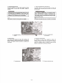
3. Screw in the cable joints (accessories) about 11 mm (0.4
in) over the ends of the remote control cables, and tighten
the lock nuts. Before installing the cable joints, apply the
water-resistance grease (Yamaha Grease A) to the holes in
the cable joints.
3. Visser les raccords de cable (accessoires) d'environ 11
mm (0,4 po) sur les extremites des cables de commande a
distance puis serrer les contre-ecrous. Avant de monter les
raccords de cable, mettre de la graisse etanche (Graisse
Yamaha A) dans leurs trous filetes.
<•0
Apply grease
Graisser
(7) Remote control cable
(2) Lock nut
(3) Cable joint ^
o,
11mm (0.4 in)
(T) Cable de commande a distance
(2) Contre-ecrou
(3) Raccord de cable
-7-

4. Insert the remote control cable outer for shifting into the
housing clamp so that the groove on its end fits over the
ridge in the clamp. Fit the cable joint over the pin on the
end of the shift arm, and lock it with the circlip.
5. Fit the grommet (accessory) in the clamp groove.
4. Inserer la gaine du cable de commande d'inversion a
distance dans la bride du boitier de maniere telle que la
gorge de son extremite s'ajuste sur la nervure de la bride.
Ajuster le raccord de cable sur la goupille de rextremite du
bras d'inversion puis le bloquer avec le circlip.
5. Ajuster Poeillet en caoutchouc (accessoire) dans la gorge
dela bride.
(T) Grommet
(2) Clamp groove
(3) Circlip
(4) Shift arm
(T) Oeillet en caoutchouc
(2) Gorge de la bride
(3) Circlip
(4) Bras d'inversion
6. Connect the remote control cable for the throttle to the
throttle arm in the same manner.
6. Raccorder le cable de commande d'acceleration a
distance au bras d'acceleration de la meme maniere.
(T) Remote control cable
for throttle
(2) Remote control cable
for shifting
(3) Circlip
(T) Cable de commande
d'acceleration a distance
(2) Cable de commande d'inversion
a distance
(3) Circlip
—8—

7. Secure the lower back panel with the two screws, and
install the wire cover.
8. After connecting the remote control cables, install the
remote control box in the previously determined position
using the accessory fittings (screws, nuts, washers, and
spacer).
TIGHTENING TORQUE:
1.2-1.5 Nm (0.12-0.15 m-kg, 0.87-1.1 ft-lb)
7. Fixer le dos inferieur avec ses deux vis puis monter le
cache de cables.
8. Apres avoir raccorde les cables de commande a distance,
monter le boitier de commande a distance a l'endroit
prealablement determine a l'aide des pieces accessoires (vis,
ecrous, rondelles et entretoise).
COUPLE DE SERRAGE:
1,2
—
1,5 Nm (0,12-0,15m-kg, 0,87- 1,1 ft
•
lb)
(T) Remote control box
©
Boitier de commande
© Screw
©
a distance
(3) Spacer ©
Vis
(4) Washer
©
Entretoise
(5) Nut
©
Rondelle
(6) Hull
©
Ecrou
©
Co que
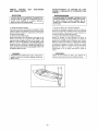
9. According to the instructions given in the respective
owner's manual of outboard motor, connect the remote
control cables both for shifting and throttle and
wireharness to the engine. When connecting, set the con-
trol lever to N, and place the neutral throttle lever in the
closed position (horizontal).
10. By operating the control lever a few times, check to see
that when the lever is turned to Forward or Reverse until it
stops once (about 32°), the gear shifts, and that when the
lever is turned further from this position to Forward, the
throttle fully opens. Next, make sure that when the control
lever is returned to N, the throttle is completely closed. If
not fully closed, adjust the positions of cable joints on the
engine side, and install them again.
9. Conformement aux instructions donnees dans le Manuel
du proprietaire du moteur hors-bord, raccorder les cables
de commande d'in version et d'acceleration a distance et le
faisceau electrique au moteur. Lors du raccordement,
mettre le levier de commande au point mort, et mettre le
levier d'acceleration au point mort en position de fermeture
(levier horizontal).
10. En actionnant le levier de commande, controler si la
marche avant et la marche arriere sont enclenchees quand il
est tourne vers la position correspondante jusqu'a ce qu'il
s'arrete (environ 32°). Contrdler aussi si l'accelerateur
souvre au maximum quand le levier est tourne davantage a
partir de cette position en marche avant. Ensuite, s'assurer
que l'accelerateur se referme completement quand le levier
de commande est remis au point mort. Si l'accelerateur
n'est pas completement ferme, regler les positions des
raccords de cable du moteur et les remettre en place.
— ATTENTION:
The cable joints on the engine side must be screw-
ed in at least 8 mm (0.3 in) over the remote control
cables.
— ATTENTION:
Les raccords de cable du moteur doivent etre visses d'au
moins 8 mm (0,3 po) sur les extremites des cables de
commande a distance.
-9-

CHANGE IN THE CONTROL LEVER POSI-
TION
The remote control box permits to change the control lever
position from the right side to the left side or vice versa.
1. Pinch the wire cover with your fingers, and pull it out to
remove.
2. Using a socket wrench (12 mm), loosen the bolt.
CHANGEMENT DE LA POSITION DU LEVI-
ER DE COMMANDE
Ce boitier de commande a distance permet de changer la
position du levier de commande du cote droit au cote
gauche, ou vice versa.
1. Saisir les deux cotes du cache de cables et le tirer pour
Tenlever.
2. A l'aide d'une cle a douille de 12 mm, desserrer le
boulon.
3. Place a punch on the bolt head, and by tapping it with a
hammer, remove the control lever from the remote control
box.
r— CAUTION: '
Use care not to damage power trim and tilt switch
leads.
3. Mettre un pointeau sur la tete du boulon et, en tapant
dessus avec un maillet, enlever le levier de commande du
boitier de commande a distance.
— ATTENTION:
Prendre garde a ne pas endommager les fils de
l'interrupteur de dispositif d'inclinaison et de relevage
assistes.
-10-
http://motorka.org

4. Loosen the two screws, and remove the neutral lock 4. Enlever les deux vis et enlever le support de verrouillage
holder. de point mort.
(T) Neutrallockholder
(T) Support de verrouillage
de point mort
5. Place the remote control box up side down, and secure
the neutral lock holder with the two screws.
5. Retourner le boitier de commande a distance puis fixer le
support de verrouillage de point mort avec ses deux vis.
TIGHTENING TORQUE:
3-4 Nm (0.3 - 0.4 m
•
kg, 2.2 - 2.9ft
•
lb)
COUPLE DE SERRAGE:
3
- 4 Nm (0,3 - 0,4 m
•
kg, 2,2 - 2,9 ft • lb)
V
en
(JlilL
® 0 w
®
V
en
0 e ^Lh
®
I
|
f
6. Install the control lever, and secure it by screwing in the
bolt from the back side and with the washer.
6. Monter le levier de commande et le fixer en vissant le
boulon, muni de sa rondelle, par derriere.
TIGHTENING TORQUE:
10-11 Nm (1.0-1.1 m-kg, 7.2-7.9ft-lb)
COUPLE DE SERRAGE:
10- 11 Nm(l,0~ 1,1m-kg, 7,2-7,9 ft-lb)
7. While taking care so that the power trim and tilt switch
leads are not twisted or slackened, install the wire cover.
7. Tout en prenant garde a ce que les fils de l'interrupteur
du dispositif d'inclinaison et de relevage assistes ne soient
pas vrilles ou aplatis, monter le cache de cables.
-11-

CHANGE FROM THE PUSH-TO-OPEN
THROTTLE TYPE TO THE PULL-TO-OPEN
THROTTLE TYPE
The remote control box permits to change from the push-
to-open throttle type to the pull-to-open type by changing
some of the parts and their positions.
This manual discusses the procedure for changing from the
push-to-open throttle type to the pull-to-open throttle type.
Therefore, if it has to be changed from the pull-to-open
type to the push-to-open type, simply reverse the pro-
cedure.
r— CAUTION:
When reinstalling parts, apply the water-resistant
grease (Yamaha Grease A) to moving parts and contact
surfaces of parts.
CHANGEMENT D'ACCELERATEUR DU
TYPE POUSSER POUR OUVRIR AU TYPE
TIRER POUR OUYRIR
Ce boitier de commande a distance permet de changer
l'accelerateur du type poursser pour ouvrir au type tirer
pour ouvrir en changeant certaines des pieces et leurs
positions. Ce manuel decrit la procedure de changement du
type pousser pour ouvrir au type tirer pour ouvrir. Par
consequent, si on veut changer l'accelerateur du type tirer
pour ouvrir au type pousser pour ouvrir, il suffit d'inverser
cette procedure.
—HMHB
Lors du remontage des pieces, mettre de la graisse
etanche (Graisse Yamaha A) sur les pieces mobiles et sur
les faces de contact des pieces.
For pull to open throttle
L'accelerateur de tirer
pour duvrir
L'accelerateur de pousser
pour ouvrir
1. Pinch the wire cover with your fingers and pull it out to
remove.
2. Loosen the screws, and remove both upper and lower
back panels.
1. Saisir les deux cotes du cache de cables et le tirer pour
l'enlever.
2. Enlever les vis et enlever les dos superieur et inferieur.
-12-

3. Loosen the two screws holding the neutral throttle lever,
and remove the throttle drum. Rotate the drum 180°, and
hold the neutral throttle lever with the same screws.
3. Desserrer les deux vis fixant le levier d'acceleration au
point mort puis enlever le tambour d'acceleration. Tourner
le tambour de 180° puis fixer le levier d'acceleration au
point mort avec ses vis.
NOTE:
Use care so that the roller does not jump out due to spring
force.
N.B.:
Prendre garde a ce que la force du ressort ne fasse pas
sauter legalet.
TIGHTENING TORQUE:
1.5 ~ 1.8 Nm (0.15 ~ 0.18 m
*
kg, 1.1
-1.3 ft - lb)
COUPLE DE SERRAGE:
1,5
—
1,8 Nm (0,15 ~ 0,18 m- kg, 1,1 ~ 1,3 ft-lb)
® Throttle drum
(2) Roller
Turn the drum 180° and install the lever.
Tourner le tambour de 180° puis mooter le levier.
(T) Tambour deceleration
(2) Galet
4. Remove the throttle arm for the push-to-open throttle
type, and install the throttle arm for the pull-to-open throt-
tle type.
4. Enlever le bras d'acceleration du type pousser pour
ouvrir et monter le bras d'acceleration du type tirer pour
ouvrir.
NOTE:
Replace the cam roller attached to the throttle arm with
the throttle arm for the pull-to-open thottle type.
N.B.:
Changer le galet de came fixes au bras d'acceleration avec
le bras d'acceleration du type tirer pour ouvrir.
(T) Cam roller
(T) Galet de came
-13-

5. Align the main shaft and throttle arm with the grooves,
and align the drive pin with the slot, and secure the upper
back panel with the three screws.
5. Aligner l'axe principal et l'axe de bras d'acceleration
avec les gorges, et aligner la goupille d'entrainement avec la
fente. Ensuite, fixer le dos superieur avec ses trois vis.
TIGHTENING TORQUE:
1.5-1.8 Nm (0.15-0.18 m -kg, 1.1 -1.3 ft-lb)
COUPLE DE SERRAGE:
1,5- 1,8 Nm (0,15-0,18m-kg, 1,1 - 1,3 ft• lb)
(T) Main shaft
(2) Throttle arm shaft
(3) Drive pin
(T) Axe principal
(2) Axe de bras d'acceleration
(3) Goupille d'entrainement
6. Secure the lower back panel with the two screws, and
install the wire cover.
6. Fixer le dos inferieur avec ses deux vis puis monter le
cache de cables.
——V®,
© e
ZB
^ / -v
(T) Back panel
® Dos
-14-

THROTTLE OPENING ADJUSTMENT AT
REVERSE
1. Remove the wire cover, loosen the screws, and remove
the upper and lower panels.
2. Loosen the lock nut, and adjust the throttle by turning
the adjust bolt. Turning the adjust bolt to the left makes the
throttle opening larger, and turning it to the right makes the
opening smaller.
AWARNING
REGLAGE DE L OUVERTURE DE L'ACCE-
LERATEUR EN MARCHE ARRIERE
1. Enlever le cache de cables, en lever les vis et enlever les
dos superieur et inferieur.
2. Desserrer le contre-ecrou et regler l'accelerateur en tour-
nant le boulon de reglage. La rotation de ce boulon vers la
gauche augmente l'ouverture; et la rotation vers la droite la
diminue.
AAVERTISSEMENT
If the reverse throttle opening is too large, it may
lead to an error in control operation. Set the con-
trol lever so that it does not turn more than 60° to
the Reverse.
Si Fouvertilre de l'accelerateur en marche arriere est
trop grande, cela risque d'entrainer une perte de con-
trole. Regler le levier de commande de maniere telle
qu
9
il ne toairae das de plus de 60° vers la position R
(marche arriere).
(T) Lock nut
(2) Adjusting bolt
(T) Contre-ecrou
(2) Boulon de reglage
3. After adjusting, tighten the adjusting bolt lock nut.
3. Apres le reglage, resserrer le contre-ecrou du boulon de
reglage.
TIGHTENING TORQUE:
1.5-1.8 Nm (0.15- 0.18 m kg, 1.1 ~ 1.3 ft-lb)
COUPLE DE SERRAGE:
1,5 ~ 1,8 Nm (0,15 ~ 0,18 m-kg, 1,1 - 1,3 ft - lb)
4. Install both upper and lower back panels, and install the
wire cover.
4. Monter les dos superieur et inferieur et le cache de
cables.
REMOTE CONTROL BOX FOR TWIN-ENGINE
When mounting two engines, use the twin-engine remote
control box.
NOTE:
Either half of the twin-engine remote control can be used
independently.
BOITIER DE COMMANDE A DISTANCE
POUR DEUX MOTEURS
Quand on monte deux moteurs, utiliser le boitier de com-
mande a distance pour moteurs jumeles.
N.B.:
Chaque moitie du boitier de commande a distance pour
moteurs jumeles peut etre utilisee independamment.
® Screw
(2) Spacer
(3) Hull
(4) Washer
(5) Nut
(D Remote control box
® Vis
(2) Entretoise
(3) Coque
(4) Rondelle
(5) Ecrou
(6) Boitier de commande
a distance
-15-
http://motorka.org

NOTES ON STORAGE
To ensure a longer life of the remote control box, be sure to
take the following steps when storing it for a long period of
time.
1) Remove the cable joints and apply water-resistant
grease (Yamaha grease A) to the threaded portion of
the inner cable.
2) Also apply water-resistant grease (Yamaha grease A) to
inner parts of the remote control box, particularly to
contact surfaces of moving parts.
If any rust is found, remove it and apply the grease.
3) Avoid bending the cables into a loop as much as possi-
ble. But if they have to be looped, the loop diameter
should be more than one meter (40 in).
4) Select a dry place for storage.
REMARQUES CONCERNANT LE REMISAGE
Pour assurer une meilleur longevite du boitier de com-
mande a distance, ne pas oublier de proceder comme suit
avant de le remiser pour une longue duree.
1) Enlever les raccords de cable et mettre de la graisse
etanche (Graisse Yamaha A) sur la partie filetee des
cables.
2) Mettre aussi de la graisse etanche (Graisse Yamaha A)
sur les pieces internes du boitier de commande a
distance, surtout sur les faces de contact des pieces
mobiles. S'il y a de la rouille, l'eliminer puis graisser.
3) Eviter autant que possible de courber les cables,. S'ils
doivent etre enroules, le di am etre d'un tour doit etre
superieur a un metre (40 po).
4) Choisir un endroit sec pour le remisage.
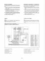
WIRING
NOTE:
Depending on the specification, some models are not
equipped with the power trim and tilt switch.
SCHEMA ELECTRIQUE
N.B.i
Suivant la specification, certains modeles ne sont pas munis
de 1'interrupteur de dispositif d'inclinaison et de relevage
assistes.
•Type with a full-line of equipment
•Modele avec la gamme complete d'equipment
Q>
\
Sb R
Lg
UP
O
O
FREE
DOWN
O
O
\
W
B
R
Y Br
PUSH
OFF
O
O
ON
START
O O O
-O
• 7OQ-Y
D>CJ-P-
\
W
B
OFF
ON
O
O
—MD<3
B
Black
Noir
Br Brown
Brun
G
Green
Vert
Gy
Gray
Gris
L Blue
Bleu
Lg
Light green
Vert clair
0
Orange
Orange
P
Pink
Rose
R
Red
Rouge
Sb Sky blue
Bleu del
W White
Blanc
Y
Yellow
Jaune
(T) Power trim and tilt switch
(2) Main switch
(3) Overheat warning buzzer
(4) Neutral switch
(5) Emergency stop switch
(7) Interrupteur de dispositif d'inclinaison et de relevage
(2) Contacteur principal
(3) Vibreur de signalisation de surchauffe
(4) Contacteur de point mort
(5) Coupe-circuit de securite
-16-

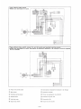
•Type without choke switch
•Modele sans interrupteur de starter
©
Sb
Ft
Lg
UP
o o
FREE
DOWN
o o
r
®
oo
[OO
a
ooo
®
©
\
W B
OFF
ON
o o
•Type without choke switch, power trim and tilt switch and overheat warning buzzer
•Modele sans interrupteur de starter, interrupteur de dispositif d'inclinaison et de relevage et vibreur de signalisa-
tion de surchauffe
©
OFF OQ
Ht-
oo
ooo
® ®
W
B
OFF
ON
O o
(T) Power trim and tilt switch
(2) Main switch
(3) Overheat warning buzzer
(4) Neutral switch
(5) Lead wire cover
(6) Engine stop switch
(D Interrupteur de dispositif d'inclinaison et de relevage
(2) Contacteur principal
(3) Vibreur de signalisation de surchauffe
@ Contacteur de point mort
(5) Couvercle de fils
(6) Coupe-circuit de securite
-17-
La page est en cours de chargement...
-
 1
1
-
 2
2
-
 3
3
-
 4
4
-
 5
5
-
 6
6
-
 7
7
-
 8
8
-
 9
9
-
 10
10
-
 11
11
-
 12
12
-
 13
13
-
 14
14
-
 15
15
-
 16
16
-
 17
17
-
 18
18
-
 19
19
-
 20
20


Yamaha Outboards 703 Mode d'emploi
- Catégorie
- Moteur
- Taper
- Mode d'emploi
dans d''autres langues
Documents connexes
Autres documents
-
Husqvarna 125R-CANADA Le manuel du propriétaire
-
Craftsman 536886480 Le manuel du propriétaire
-
Poulan PP446ET Le manuel du propriétaire
-
HPI Racing Baja 5SC SS Manuel utilisateur
-
Weed Eater VS2000BV Le manuel du propriétaire
-
HPI Racing Baja 5R Manuel utilisateur
-
-
Suzuki DF140A Le manuel du propriétaire
-
MOTO GUZZI Quota 1000 Le manuel du propriétaire
-