ASSEMBLY MANUAL
MANUEL DE MONTAGE
PR3000

Table of Contents
Before Assembly...................................................................... 2
Tools ........................................................................................... 2
Important Safety Instructions ................................................ 3
Hardware .................................................................................. 4
Parts ........................................................................................... 5
Assembly ................................................................................... 6
Assemble the Base ..........................................................6
Attach the Rod Pack ........................................................7
Attach the Lower Lat Assembly ..................................... 8
Attach the Seat Support Rail .......................................... 9
Attach Pulley Arms .........................................................10
Attach the Seat Bottom to the Seat Backbone .........11
Attach Leg Extension Assembly ...................................12
Attach Seat Back ............................................................13
Attach the Lat Crossbar with Pulleys ........................................... 14
Attach the Rear Lat Cross Bar ......................................15
Attach the Upper Lat Tower Assembly .......................16
Attach the Lat Pulley Housing ...................................... 17
Cable and Pulley Routing ..............................................18
Connect the Rod Cables ................................................ 19
Connect the Right Cable ................................................20
Leg Extension Cable Routing ........................................ 21
Final Inspection ...............................................................21
Gymnase à domicile PR3000 ............................................... 22
Contacts................................................................................... 44
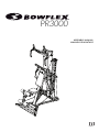
Before Assembly
Select where you are going to locate your Bowflex® home gym carefully. The best location is on a hard, level surface. For best
results, assemble your home gym in the location where you intend to use it. For safe operation, allow a workout area of at least
100” x 86” (2.6m x 2.2m) of free space.
Follow these basic tips when assembling your home gym
.
1. Collect all the pieces needed for each assembly step.
2. Turn all the bolts and locknuts toward the right to tighten
. Turn towards the left to loosen.
3. Use a combination wrench to grip the locknut when you tighten a bolt that has a locknut to make sure it is tight.
4.
You may find the use of a utility knife or scissors beneficial during the unpacking and assembly process.
5. Carefully lift pieces when attaching. Look through the bolt holes to help guide bolt placement.
6. Assembly requires 2 people.
NOTICE: Leave all of the cables wrapped and bagged until the Bowflex® home gym is completely assembled.
Tools
• (2) Adjustable Wrenches (not included)
• Phillips Head Screwdriver (not included)
Assembly Manual
2

Important Safety Instructions
• Keep bystanders and children away from the product you are assembling at all times.
• Do not assemble this machine outdoors or in a wet or moist location.
• Make sure assembly is done in an appropriate work space away from foot traffic and exposure to bystanders.
• Some components of the machine can be heavy or awkward. Use a second person when doing the assembly
steps involving these parts. Do not do steps that involve heavy lifting or awkward movements on your own.
• Set up this machine on a solid, level, horizontal surface.
• Do not try to change the design or functionality of this machine. This could compromise the safety and can void
the warranty.
• If replacement parts are necessary use only genuine Nautilus replacement parts and hardware. Failure to
use genuine replacement parts can cause a risk to users, keep the machine from operating correctly or void the
warranty.
• Do not use or put the machine into service until the machine has been fully assembled and inspected for correct
performance in accordance with the Owner’s Manual.
• Read and understand the complete Owner’s Manual supplied with this machine before first use. Keep the
Owner’s and Assembly Manuals for future reference.
This icon means a potentially hazardous situation which, if not avoided, could result in death or serious
injury.
Read and understand all warnings on this machine.
Carefully read and understand the Assembly Manual.
Obey the following warnings:
Assembly Manual
3

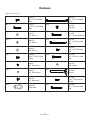
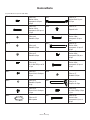
Hardware
(Hardware not actual size)
Qty. 13 Item #1
3/8”x 3/4” Hex Head
Bolt
Qty. 2 Item #11
1/2” x 9 1/2” Threaded
Stud
Qty. 2 Item #2
5/16”x 2 1/2” Hex Head
Bolt
Qty. 4 Item #12
Ball Stop
Qty. 5 Item #3
1/4” Washer
Qty. 2 Item #13
3/8” x 3” Hex Head Bolt
Qty. 4 Item #4
1/2” Washer
Qty. 2 Item #14
1/2” x 5 1/4” Hex Head
Bolt
Qty. 29 Item #5
3/8” Washer
Qty. 4 Item #15
5/16” x 3/4” Hex Head
Bolt
Qty. 3 Item #6
#10 x 1” Phillips Head
Screw
Qty. 4 Item #16
3/8” x 2 3/4” Hex Head
Bolt
Qty. 8 Item #7
3/8” Nylock Nut
Qty. 6 Item #17
5/16” Washer
Qty. 4 Item #8
1/2” Wide Washer
Qty. 1 Item #18
Seat Pin
Qty. 6 Item #9
1/2” Nylock Nut
Qty. 2 Item #19
1/4 x 1” Phillips Head
Screw
Qty. 6 Item #10
Snap Hook
Qty. 2 Item #20
3/8” x 3 1/4” Hex Head
Bolt
Assembly Manual
4

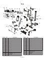
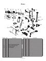
Parts
21 1 Base Platform
22 1 Right Frame Rail
23 1 Left Frame Rail
24 1 Rear Cross Bar
25 1 Central Support
26 1 Lat Cross Bar with Pulleys
27 1 Rear Lat Cross Bar
28 1 Upper Lat Tower
29 1 Right Pulley Arm
30 1 Left Pulley Arm
31 1 Rod Pack
32 1 Lower Lat Tower
33 1 Seat Back
34 1 Seat Backbone
35 1 Seat Bottom
36 1 Seat Support Rail
37 2 Floating Pulleys
38 1 Lat Pulley Housing
39 1 Leg Extension Assembly
40 2 Roller Tubes
41 4 Foam Roller Pads
42 1 Placard
43 1 Rod Pack Strap
44 2 Adjustable Handgrips
45 2 Handgrips
46 1 Accessory Bag #1
47 2 Leg Press Extension Cables
48 1 Snap Hook
49 1 Accessory Bag #2
50 4 Roller End Caps
51 1 Seat Backbone Lock Pin
52 1 Leg Extension Lock Pin
53 1 Hardware Bag
54 1 Manual Kit
55 1 Rod Box End Plate
Item # Item #
Qty. Qty.
Description Description
21
22
23
24
25
26
27
28
29
30
31
32
33
34
35 36
37
38
39
40
41
42
43 44 45
46
47
48
49
50
51
52
53 54
55
Assembly Manual
5

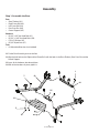
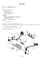
Assembly
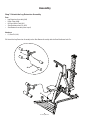
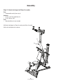
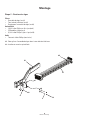
Step 1: Assemble the Base
Parts
• Base Platform (#21)
• Right Frame Rail (#22)
• Left Frame Rail (#23)
• Rear Cross Bar (#24)
• Central Support (#25)
Hardware
• (4) 3/8” x 3/4” Hex Head Bolts (#1)
• (4) 3/8” x 2 3/4” Hex Head Bolts (#16)
• (12) 3/8” Washers (#5)
• (4) 3/8” Nylock Nuts (#7)
Tools
• (2) Adjustable Wrenches (not included)
1-1 Put the Base Assembly parts on the floor.
1-2 Align the bolt holes on the Right and Left Frame Rails with the holes in the Base Platform, Rear Cross Bar and the
Central Support.
1-3 Insert all the hardware, but do not tighten.
1-4 With all the hardware in place, tighten it.
22
23
24
21
5
16
25
1
7
Assembly Manual
6

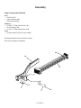
Assembly
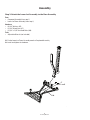
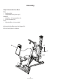
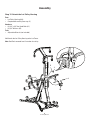
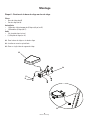
Step 2: Attach the Rod Pack
Parts
• Rod Pack (#31)
• Lower Lat Tower (#32)
• Rod Pack Strap (#43)
Hardware
• (3) #10 x 1” Phillips Head Screws (#6)
• (5) 1/4” Washers (#3)
• (2) 1/4 x 1” Phillips Head Screws (#19)
Tools
• Phillips Head Screw Driver (not included)
2-1 Slide the Rod Pack into the Lower Lat Tower.
2-2 Install and tighten the hardware.
32
31
43
3
6
19
3
Assembly Manual
7

Assembly
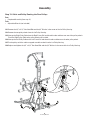
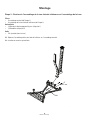
Step 3: Attach the Lower Lat Assembly to the Base Assembly
Parts
• Competed Assembly (from step 1)
• Lower Lat Tower Assembly (from step 2)
Hardware
• (4) 3/8” Washers (#5)
• (2) 3/8” Nylock Nuts (#7)
• (2) 3/8” x 3 1/4” Hex Head Bolts (#20)
Tools
• Adjustable Wrench (not included)
3-1 Put the Lower Lat Tower Assembly onto the Completed Assembly.
3-2 Install and tighten the hardware.
5
7
20
Assembly Manual
8

Assembly
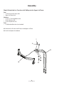
Step 4: Attach the Seat Support Rail
Parts
• Seat Support Rail (#36)
• Completed Assembly (from step 3)
Hardware
• (4) 3/8” x 3/4” Hex Head Bolts (#1)
• (4) 3/8” Washers (#5)
Tools
• Adjustable Wrench (not included)
4-1 Attach the Seat Support Rail to the Lower Lat Tower.
4-2 Install and tighten the hardware.
5
1
36
Assembly Manual
9

Assembly
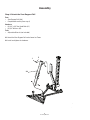
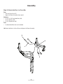
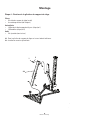
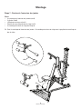
Step 5: Attach the Pulley Arms
Parts
• Right Pulley Arm (#29)
• Left Pulley Arm (#30)
• Completed Assembly (from step 4)
Hardware
• (2) 1/2” x 9 1/2” Threaded Studs (#11)
• (4) 1/2” Wide Washers (#8)
• (4) 1/2” Nylock Nuts (#9)
Tools
• (2) Adjustable Wrenches (not included)
5-1 Attach the the Right and Left Pulley Arms to the Completed Assembly.
5-2 Install and tighten the hardware.
9
8
9
11
8
29
30
Assembly Manual
10

Assembly
Step 6: Attach the Seat Bottom to the Seat Backbone
Parts
• Seat Bottom (#35)
• Seat Backbone (#34)
Hardware
• (4) 5/16” x 3/4” Hex Head Bolts (#15)
• (4) 5/16” Washers (#17)
• (1) Seat Pin (#18)
Tools
• Adjustable Wrench (not included)
6-1 Attach the Seat Bottom to the Seat Backbone.
6-2 Install and tighten the hardware.
6-3 Attach to Seat Support Rail.
35
34
17
15
18
Assembly Manual
11

Assembly
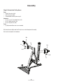
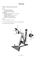
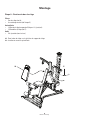
Step 7: Attach the Leg Extension Assembly
Parts
• Leg Extension Assembly (#39)
• Roller Tubes (#40)
• (4) Foam Roller Pads (#41)
• Seat Backbone Lock Pin (#51)
• Seat Bottom Assembly (from step 6)
Hardware
• (1) Seat Pin (#18)
7-1 Attach the Leg Extension Assembly to the Seat Bottom Assembly with the Seat Backbone Lock Pin.
39
51
41
40
Assembly Manual
12

Assembly
Step 8: Attach the Seat Back
Parts
• Seat Back (#33)
• Completed Assembly (from step 5)
Hardware
• (2) 5/16” x 2 1/2” Hex Head Bolts (#2)
• (2) 5/16” Washers (#17)
Tools
• Adjustable Wrench (not included)
8-1 Attach the Seat Back to the Seat Support Rail.
8-2 Install and tighten the hardware.
33 17
2
Assembly Manual
13

Assembly
Step 9: Attach the Lat Crossbar with Pulleys to the Upper Lat Tower
Parts
• Lat Crossbar with Pulleys (#26)
• Upper Lat Tower (#28)
Hardware
• (2) 3/8” x 3” Hex Head Bolts (#13)
• (4) 3/8” Washers (#5)
• (2) 3/8” Nylock Nuts (#7)
Tools
• (2) Adjustable Wrenches (not included)
9-1 Attach the Lat Crossbar with Pulleys to the Upper Lat Tower.
9-2 Install and tighten the hardware.
7
5
13
28
26
Assembly Manual
14

Assembly
Step 10: Attach the Rear Lat Cross Bar
Parts
• Rear Lat Cross Bar (#27)
• Upper Lat Tower Assembly (from step 9)
Hardware
• (2) 1/2” x 5 1/4” Hex Head Bolts (#14)
• (4) 1/2” Washers (#4)
• (2) 1/2” Nylock Nuts (#9)
Tools
• (2) Adjustable Wrenches (not included)
10-1 Attach the Rear Lat Cross Bar to the Upper Lat Tower Assembly.
27
14
4
9
Assembly Manual
15

Assembly
Step 11: Attach the Upper Lat Tower Assembly
Parts
• Completed Assembly (from step 8)
Hardware
• (2) 3/8” x 3/4” Hex Head Bolts (#1)
• (2) 3/8” Washers (#5)
Tools
• Adjustable Wrench (not included)
11-1 Attach the Upper Lat Tower Assembly to the Base Assembly.
11-2 Install and tighten the hardware.
5
1
Assembly Manual
16

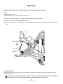
Assembly
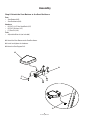
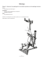
Step 12: Attach the Lat Pulley Housing
Parts
• Lat Pulley Housing (#38)
• Completed Assembly (from step 11)
Hardware
• (3) 3/8” x 3/4” Hex Head Bolts (#1)
• (3) 3/8” Washers (#5)
Tools
• Adjustable Wrench (not included)
12-1 Attach the Lat Pulley Housing to the Lat Tower.
Note: Rod Pack removed from illustration for clarity.
1
1
38
5
Assembly Manual
17

Assembly
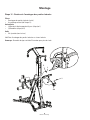
Step 13: Cable and Pulley Routing the Rear Pulleys
Parts
• Completed Assembly (from step 12)
Tools
• Adjustable Wrench (not included)
13-1 Remove the 3/8” x 4 1/2” Hex Head Bolt and the 3/8” Washer in the center of the Lat Pulley Housing.
13-2 Remove the two pulley wheels from the Lat Pulley Housing.
13-3 Unwrap the Right Pulley Cable from the Right Frame Rail and thread it under and then over one of the pulley wheels.
Pinch the Right Pulley Cable to the pulley wheel until installed.
13-4 Unwrap the Left Pulley Cable on the Left Frame Rail and thread it under and then over the other pulley wheel.
13-5 Put the pulleys with the cables wrapped around them back into the Lat Pulley Housing.
13-6 Replace and tighten the 3/8” x 4 1/2” Hex Head Bolt and the 3/8” Washer in the center of the Lat Pulley Housing.
Assembly Manual
18

Assembly
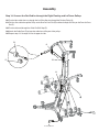
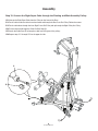
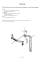
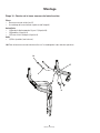
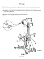
Step 14: Connect the Rod Cables through the Right Floating and Lat Tower Pulleys
14-1 Put the right cable that runs through the Lat Pulley Housing through the Floating Pulley (A).
14-2 Pull the same cable through the Pulley on the Rear Lat Cross Bar (B) and then through the Pulley on the Front Lat Cross
Bar (C).
14-3 Put the cable end through the Cable End Ball Stop (D).
14-4 Attach the Cable Core (E) to keep the cable from falling out of the pulleys.
14-5 Repeat steps 14-1 through 14-4 on the opposite side.
A
C
B
D
E
Assembly Manual
19

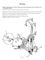
Assembly
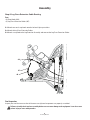
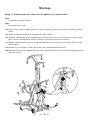
Step 15: Connect the Right Squat Cable through the Floating and Main Assembly Pulleys
15-1 Unwrap the Right Squat Cable from the Pulley on the front of the Base.
15-2 Put the cable under the cable shroud and under and through the Rear Cross Bar Pulley. Follow the arrows.
15-3 Put the cable down through the Inner Right Frame Rail Pulley and up through the Right Pulley Arm Pulley.
15-4 Put the cable end through the Cable End Ball Stop (A).
15-5 Attach the Cable Core (B) to keep the cable from falling out of the pulleys.
15-6 Repeat steps 15-1 through 15-5 on the opposite side.
A
B
Assembly Manual
20
La page est en cours de chargement...
La page est en cours de chargement...
La page est en cours de chargement...
La page est en cours de chargement...
La page est en cours de chargement...
La page est en cours de chargement...
La page est en cours de chargement...
La page est en cours de chargement...
La page est en cours de chargement...
La page est en cours de chargement...
La page est en cours de chargement...
La page est en cours de chargement...
La page est en cours de chargement...
La page est en cours de chargement...
La page est en cours de chargement...
La page est en cours de chargement...
La page est en cours de chargement...
La page est en cours de chargement...
La page est en cours de chargement...
La page est en cours de chargement...
La page est en cours de chargement...
La page est en cours de chargement...
La page est en cours de chargement...
La page est en cours de chargement...
-
 1
1
-
 2
2
-
 3
3
-
 4
4
-
 5
5
-
 6
6
-
 7
7
-
 8
8
-
 9
9
-
 10
10
-
 11
11
-
 12
12
-
 13
13
-
 14
14
-
 15
15
-
 16
16
-
 17
17
-
 18
18
-
 19
19
-
 20
20
-
 21
21
-
 22
22
-
 23
23
-
 24
24
-
 25
25
-
 26
26
-
 27
27
-
 28
28
-
 29
29
-
 30
30
-
 31
31
-
 32
32
-
 33
33
-
 34
34
-
 35
35
-
 36
36
-
 37
37
-
 38
38
-
 39
39
-
 40
40
-
 41
41
-
 42
42
-
 43
43
-
 44
44