Broan RM503004 Manuel utilisateur
- Catégorie
- Hottes
- Taper
- Manuel utilisateur

RM50000
Series
Broan-NuTone LLC. 926 West State Street, Hartford, WI 53027
NuTone, Inc., 4820 Red Bank Road, Cincinnati, OH 45227
Broan-NuTone Canada, Inc.1140 Tristar Drive, Mississauga, Ontario, L5T 1H9
ENGLISH ........................................... 2
FRANÇAIS
....................................... 12
ESPAÑOL ....................................... 22

2
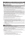
READ AND SAVE THESE INSTRUCTIONS
WARNING
TO REDUCE THE RISK OF FIRE, ELECTRIC SHOCK, OR INJURY TO PERSONS,
OBSERVE THE FOLLOWING:
1. Use this unit only in the manner intended by the manufacturer. If you have questions,
contact the manufacturer at the address or telephone number listed in the warranty.
2. Before servicing or cleaning unit, switch power off at service panel and lock service
panel to prevent power from being switched on accidentally. When the service
disconnecting means cannot be locked, securely fasten a prominent warning device,
such as a tag, to the service panel.
3. Installation work and electrical wiring must be done by a qualified person(s) in accor-
dance with all applicable codes and standards, including fire-rated construction codes
and standards.
4. Sufficient air is needed for proper combustion and exhausting of gases through the flue
(chimney) of fuel burning equipment to prevent backdrafting. Follow the heating equip-
ment manufacturer’s guidelines and safety standards such as those published by the
National Fire Protection Association (NFPA), and the American Society for Heating,
Refrigeration and Air Conditioning Engineers (ASHRAE), and the local code authorities.
5. When cutting or drilling into wall or ceiling, do not damage electrical wiring and other
hidden utilities.
6. Ducted fans must always be vented to the outdoors.
7. Do not use this unit with any separate solid-state speed control device.
8. To reduce the risk of fire, use only steel ductwork.
9. This unit must be grounded.
TO REDUCE THE RISK OF A RANGE TOP GREASE FIRE:
A. Never leave surface units unattended at high settings. Boilovers cause smoking and
greasy spillovers that may ignite. Heat oils slowly on low or medium settings.
B. Always turn hood ON when cooking at high heat or when flambeing food (i.e. Crepes
Suzette, Cherries Jubilee, Peppercorn Beef Flambe’).
C. Clean ventilating fans frequently. Grease should not be allowed to accumulate on fan or
filter.
D. Use proper pan size. Always use cookware appropriate for the size of the surface
element.
WARNING
TO REDUCE THE RISK OF INJURY TO PERSONS IN THE EVENT OF A RANGE TOP
GREASE FIRE, OBSERVE THE FOLLOWING:*
1. SMOTHER FLAMES with a close-fitting lid, cookie sheet, or metal tray, then turn off the
burner. BE CAREFUL TO PREVENT BURNS. If the flames do not go out immediately,
EVACUATE AND CALL THE FIRE DEPARTMENT.
2. NEVER PICK UP A FLAMING PAN - You may be burned.
3. DO NOT USE WATER, including wet dishcloths or towels - violent steam explosion will
result.
4. Use an extinguisher ONLY if:
A. You know you have a Class ABC extinguisher and you already know how to operate
it.
B. The fire is small and contained in the area where it started.
C. The fire department is being called.
D. You can fight the fire with your back to an exit.
* Based on “Kitchen Fire Safety Tips” published by NFPA.
!
INTENDED FOR DOMESTIC COOKING ONLY
!

3
!
CAUTION
1. To reduce risk of fire and to properly exhaust air, be sure to duct air outside. Do not vent
exhaust air into spaces within walls or ceilings or into attics, crawl spaces, or garages.
2. Take care when using cleaning agents or detergents.
3. Avoid using food products that produce flames under the Range Hood.
4. For general ventilating use only. Do not use to exhaust hazardous or explosive materials
and vapors.
5. To avoid motor bearing damage and noisy and/or unbalanced impellers, keep drywall
spray, construction dust, etc. off power unit.
6. Your hood motor has a thermal overload which will automatically shut off the motor if it
becomes overheated. The motor will restart when it cools down. If the motor continues
to shut off and restart, have the hood serviced.
7. For best capture of cooking impurities, the bottom of the hood should be a minimum of
24" and a maximum of 30" above the cooking surface.
8. Two installers are recommended because of the large size and weight of this hood.
9. This product is equipped with a thermostat which may start blower automatically. To
reduce the risk of injury and to prevent power from being switched on accidentally,
switch power off at service panel and lock or tag service panel.
10. Please read specification label on product for further information and requirements.

4
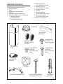
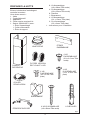
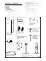
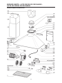
PREPARE THE HOOD
Unpack hood and check contents.
You should receive:
1 - Hood
1 - Decorative Flue Assembly
1 - Adapter
2 - Non-ducted recirculation filters
1 - Parts Bag (B080810471) containing:
1 - Mounting Bracket
1 - Discharge Collar
1 - Flue Mounting Bracket
MOUNTING
BRACKET
DISCHARGE
COLLAR
FLUE MOUNTING BRACKET
8 MOUNTING SCREWS
(4.8 x 38mm Pan Head)
8 DRYWALL
ANCHORS
4 MOUNTING
SCREWS (3.9 x
9.5mm Pan Head)
DECORATIVE
FLUE
4 MOUNTING
SCREWS
(3.4 x 15mm Flat
Head)
8 - Mounting Screws
(4.8 x 38mm Pan Head)
4 - Mounting Screws
(3.9 x 9.5mm Pan Head)
8 - Drywall Anchors
1 - Plenum
4 - Mounting Screws
(3.4 x 15mm Flat Head)
2 - Mounting Screws
(3.9 x 6mm Flat Head)
1 - Installation Instructions
ADAPTER
NON-DUCTED
RECIRCULATION
FILTERS
PLENUM
fig.1
2 MOUNTING
SCREWS
(3.9 x 6mm Flat
Head)

5
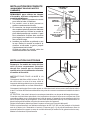
ROOF CAP
ROUND
DUCT
DECORATIVE
FLUE
HOOD
WALL
CAP
24” TO 30” ABOVE
COOKING SURFACE
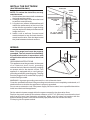
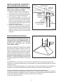
INSTALL THE DUCTWORK
(DUCTED HOODS ONLY)
NOTE: To reduce the risk of fire, use only
metal ductwork.
1. Decide where the ductwork will run between
the hood and the outside.
2. A straight, short duct run will allow the hood
to perform most efficiently.
3. Long duct runs, elbows, and transitions will
reduce the performance of the hood. Use
as few of them as possible. Larger ducting
may be required for best performance with
longer duct runs.
4. Install a roof or wall cap. Connect round
metal ductwork to cap and work back to-
wards hood location. Use duct tape to seal
the joints between ductwork sections.
6”
ADAPTER
fig.2
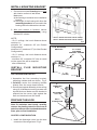
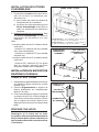
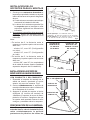
WARNING - Improper grounding can result in a risk of electric shock.
Consult a qualified electrician if the grounding instructions are not completely understood, or if
doubt exists as to whether the appliance is properly grounded.
Do not use an extension cord. If the power supply cord is too short, have a qualified electrician
install an outlet near the appliance.
Set the electrical power supply within the space covered by the decorative flues.
Position the power socket at a maximum distance of 33-7/16” (850 mm) from where the lead
exits from the hood (see illustration alongside). Make sure this does not interfere with the
bracket fastening area or with the decorative pipe (where the flue touches the wall).
Fit the plug into the power socket.
WIRING
Note: This range hood must be properly
grounded. The unit should be installed by
a qualified electrician in accordance with
all applicable national and local electrical
codes.
GROUNDING INSTRUCTIONS
This appliance must be grounded. In the event
of an electrical short circuit, grounding
reduces the risk of electric shock by providing
an escape wire for the electric current. This
appliance is equipped with a cord having a
grounding wire with a grounding plug. The plug
must be plugged into an outlet that is properly
installed and grounded.
fig.3
33-7/16"
(85cm)
max

6
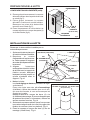
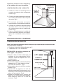
DISCHARGE
COLLAR
6”
DIAMETER
DUCT
DUCT
CONNECTOR
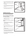
INSTALL FLUE MOUNTING
BRACKET
DUCTED AND NON-DUCTED
1. Assemble the flue mounting bracket,
adjusting outside width as shown. Fig.5
2. Carefully center the mounting bracket
directly over the range hood location.
3. Secure the bracket assembly to the ceiling
using (2) 4.8x38mm mounting screws and
drywall anchors. Make sure the bracket is
pushed into the corner, tight against the
wall and centered over the hood.
FLUE MOUNTING
BRACKET
7 - 3/4”
(197mm)
3.9 x 6mm
FLAT HEAD
BRACKET SCREWS
INSTALL MOUNTING BRACKET
1. Construct wood wall framing that is flush
with interior surface of wall studs.
Make sure:
a) the framing is centered over installation
location.
b) the height of the framing will allow the
mounting bracket to be secured to the
framing within the dimensions shown.
2. After wall surface is finished, secure
mounting bracket to framing using
dimensions shown.
NOTE:
- On 8’ ceilings, the hood distance above
cook top is :
minimum 24”, maximum 28” (for Ducted
Configuration).
minimum 24”, maximum 27” (for Non-Ducted
Configuration).
- On 9’ ceilings, the hood distance above
cook top is :
- minimum 28”, maximum 30” (the air vents
on the upper flue will be exposed
after installation).
FRAMING BEHIND DRYWALL
36 3/4"= bottom of hood 24" above cooktop
42 3/4"= bottom of hood 30" above cooktop
36 3/4” to 42 3/4” above
cooktop
fig.4
fig.5
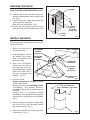
PREPARE THE HOOD
Note: On stainless steel hoods, carefully
remove the plastic protective film from all
exterior surfaces of the hood and decorative
flues, prior to final installation.
DUCTED CONFIGURATION
1. Install the discharge collar into the duct
connector of the range hood. Fig.6
fig.6

7
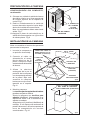
A
fig.7
UPPER
FLUE
LOWER
FLUE
UPPER
FLUE
VENTS
EXPOSED
UPPER
FLUE
VENTS
CONCEALED
PLENUM
(3) SCREWS
5” ALUMINUM
FLEX DUCT
5” 6” ADAPTER
BLOWER
COLLAR
PREPARE THE HOOD
NON - DUCTED CONFIGURATION
Note: The following materials must be
purchased separately for non-ducted
recirculation installations.
• 5” diameter expandable / flexible aluminum
duct.
• 1/16” diameter twist drill.
CAUTION: Do not use plastic or rigid metal
ducting.
1. Discard discharge collar and damper
supplied with the hood. Install the 5” to 6”
adapter (supplied).
2. Measure the distance “A”
3. Attach aluminum flexible duct to the 5”
adapter. Tape all joints with duct tape.
Fig.8
4. Assemble the recirculation plenum to the
flexible duct. Fig.8
5. Drill three (3) 1/16” diameter equally spaced
holes through the duct and duct connector
of the recirculation plenum. Fig.8
6. Secure duct to the plenum’s connector with
(3) sheet metal screws. Tape all joints with
duct tape. Fig.8
fig.8
2. Attach an adequate length of 6” round steel
ducting to the range hood duct connector.
Fig.6
3. Duct tape all joints to make them secure
and air tight.
4. Carefully place the lower decorative flue
into the recessed area of the range hood
top. Fig. 7
5. Carefully slide the upper decorative flue
down inside the lower flue. Fig. 7

8
PREPARE THE HOOD
NON - DUCTED CONFIGURATION, cont’d.
8. Carefully place the lower decorative flue
into the recessed area of the range hood
top. Fig.7
9. Carefully slide the upper decorative flue
down inside the lower flue.
Note: air vents must be up. Fig.7
10.Secure the recirculation plenum to the
upper flue with (4) flat head screws. Fig.9
PLENUM
4 FLAT
HEAD
SCREWS
(3.4x15 mm)
UPPER
FLUE
fig.9
fig.10
RECTANGULAR
CUTOUT
HEIGHT
ADJUSTMENT
SCREWS
(3.9x9.5mm)
WALL FRAMING
MOUNTING
BRACKET
INSTALL THE HOOD
Note: at least two people will be required to
mount the hood.
1. Raise the hood into its
mounting position.
2. Plug the power cord into
the electric wall recep-
tacle. Tuck excess cord
behind the flue.
3. Align the rectangular
opening on the back of
the hood with the wall-
mounting bracket. Gently
lower the hood until it
securely engages the
bracket. Fig.10
4. Level the hood.
Height adjustment screws provide
vertical adjustment.
Secure the hood with mounting screws
(4.8x38mm). Use drywall anchors,
provided, if wall studs or framing are not
available.
Secure with (2) mounting screws
(4.8x38mm). Use drywall anchors provided
if wall studs or framing are not available.
Fig.10
5. Raise the upper flue until its holes align
with holes in the flue mounting bracket
(located on ceiling). Fig.11
6. Secure the flue with (2) mounting screws
(3.9x9.5mm). Fig.11
fig.11
FASTEN FLUE TO
UPPER BRACKET
WITH SCREWS (3.9x9.5mm)
MOUNTING
SCREWS
(4.8x38mm)
MOUNTING
SCREWS
(4.8x38mm)

9
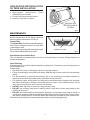
Non-ducted recirculation filters
The non-ducted recirculation filters should be changed every 6 months. Rotate the filters to
remove and replace.
Hood Cleaning
Stainless steel is one of the easiest materials to keep clean. Occasional care will help preserve
its fine appearance.
Cleaning tips:
• Hot water with soap or detergent is all that is usually needed.
• Follow all cleaning by rinsing with clear water. Wipe dry with a clean, soft cloth to avoid water
marks.
• For discolorations or deposits that persist, use a non-scratching household cleanser or
stainless steel polishing powder with a little water and a soft cloth.
• For stubborn cases, use a plastic scouring pad or soft bristle brush together with cleanser
and water. Rub lightly in direction of polishing lines or "grain" of the stainless finish. Avoid
using too much pressure which may mar the surface.
• DO NOT allow deposits to remain for long periods of time.
• DO NOT use ordinary steel wool or steel brushes. Small bits of steel may adhere to the
surface causing rust.
• DO NOT allow salt solutions, disinfectants, bleaches, or cleaning compounds to remain in
contact with stainless steel for extended periods. Many of these compounds contain chemi-
cals which may be harmful. Rinse with water after exposure and wipe dry with a clean cloth.
Painted surfaces should be cleaned with warm water and mild detergent only.
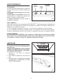
GREASE FILTER
NON-DUCTED RECIRCULATION
FILTERS INSTALLATION
1. Non-ducted recirculation filters
(B03300487) is included.
2. Position the filters over the blower.
3. Rotate to lock filters in place.
NON-DUCTED
RECIRCULATION
FILTERS
fig.12
fig.13
MAINTENANCE
Proper maintenance of the Range Hood will
assure proper performance of the unit.
Grease Filter
The grease filter should be cleaned frequently.
Use a warm detergent solution. Grease filter
is dishwasher safe.
Remove filter by pushing filter towards the back
of hood and rotating filter downward.

10
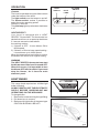
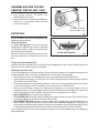
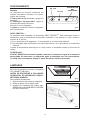
OPERATION
Controls
The hood is operated using the slide controls
under the bottom of the hood.
The light switch turns the lamps on and off.
The blower switch: makes it possible to
select the motor operating speed.
Position 0: motor off.
The pilot lamp lights up whenever the blower
is on.
HEAT SENTRY™
Your hood is equipped with a HEAT
SENTRY™ thermostat. This thermostat is a
device that will turn on or speed up the blower
if it senses excessive heat above
the cooking surface.
1) If blower is OFF - it turns blower ON to
HIGH speed.
2) If blower is ON at a lower speed setting -
it turns blower up to HIGH speed.
When the temperature level drops to normal,
the blower will return to its original setting.
WARNING
The HEAT SENTRY thermostat can start
the blower even if the hood is turned OFF.
When this occurs, it is impossible to turn
the blower OFF with its switch. If you must
stop the blower, do it from the main
electrical panel.
LIGHT BULBS
This range hood requires two 40-Watt light
bulbs (included).
ALWAYS SWITCH OFF THE ELECTRICITY
SUPPLY BEFORE CARRYING OUT ANY
OPERATIONS ON THE APPLIANCE.
To change bulbs:
1. Remove the screw securing the light fitting.
2. Pull down lens to remove.
3. Replace with light bulbs of the same type.
CAUTION: BULB MAY BE HOT!
fig.14
LIGHT
SWITCH
PILOT
LAMP
BLOWER
SWITCH
01 01234
fig.15
fig.16

11
BROAN-NUTONE LLC ONE YEAR LIMITED WARRANTY
Broan-NuTone LLC warrants to the original consumer purchaser of its products that such products will
be free from defects in materials or workmanship for a period of one year from the date of original
purchase. THERE ARE NO OTHER WARRANTIES, EXPRESS OR IMPLIED, INCLUDING, BUT NOT
LIMITED TO, IMPLIED WARRANTIES OR MERCHANT ABILITY OR FITNESS FOR A PARTICULAR
PURPOSE.
During this one-year period, Broan-NuTone LLC will, at its option, repair or replace, without charge, any
product or part which is found to be defective under normal use and service.
THIS WARRANTY DOES NOT EXTEND TO FLUORESCENT LAMP STARTERS, TUBES, HALOGEN
AND INCANDESCENDT BULBS. This warranty does not cover (a) normal maintenance and service or
(b) any products or parts which have been subject to misuse, negligence, accident, improper mainte-
nance or repair (other than by Broan-NuTone LLC), faulty installation or installation contrary to
recommended installation instructions.
The duration of any implied warranty is limited to the one-year period as specified for the express
warranty. Some states do not allow limitation on how long an implied warranty lasts, so the above
limitation may not apply to you.
BROAN-NUTONE LLC’S OBLIGATION TO REPAIR OR REPLACE, AT BROAN-NUTONE LLC’S OPTION,
SHALL BE THE PURCHASER’S SOLE AND EXCLUSIVE REMEDY UNDER THIS WARRANTY. BROAN-
NUTONE LLC SHALL NOT BE LIABLE FOR INCIDENTAL, CONSEQUENTIAL OR SPECIAL DAM-
AGES ARISING OUT OF OR IN CONNECTION WITH PRODUCT USE OR PERFORMANCE. Some
states do not allow the exclusion or limitation of incidental or consequential damages, so the above
limitation or exclusion may not apply to you.
This warranty gives you specific legal rights, and you may also have other rights, which vary from state
to state. This warranty supersedes all prior warranties.
To qualify for warranty service, you must (a) notify Broan-NuTone LLC at the address stated below or
telephone: 1-800-637-1453, (b) give the model number and part identification and (c) describe the nature
of any defect in the product or part. At the time of requesting warranty service, you must present
evidence of the original purchase date.
Broan-NuTone LLC. 926 West State Street, Hartford, WI 53027 (1-800-637-1453)
NuTone, Inc., 4820 Red Bank Road, Cincinnati, OH 45227 (1-800-543-8687)
Broan-NuTone Canada, Inc. 1140 Tristar Drive, Mississauga, Ontario, L5T 1H9 (1-888-882-7626)
WARRANTY

12
LISEZ ET CONSERVEZ CES INSTRUCTIONS
AVERTISSEMENTS
POUR REDUIRE LES RISQUES D’INCENDIE, DE DECHARGES ELECTRIQUES OU
DE DOMMAGES AUX PERSONNES, OBSERVEZ LES INSTRUCTIONS SUIVANTES:
1. N’utilisez cet appareil que comme cela est indiqué par le constructeur. Si vous avez des
problèmes, contactez le fabriquant à l’adresse ou au numéro de téléphone indiqués dans
la garantie.
2. Avant de pourvoir à l’entretien ou au nettoyage de votre appareil, éteignez-le au tableau
des commandes ou bloquez le tableau des commandes afin d’éviter de le mettre en marche
accidentellement. Si vous ne pouvez pas bloquer le système permettant d’éteindre votre
appareil, appliquez un avertissement extérieur d’une façon sure, comme par exemple un
panneau, sur le tableau des commandes.
3. L’assemblage et la connexion électrique doivent être faits par des personnes qualifiées
en respectant les normes et règlements en vigueur, y compris les normes et règlements
concernant les possibilités d’incendie.
4. Il est indispensable qu’il y ait suffisamment d’air pour que la combustion et l’évacuation des
gaz à travers le tuyau du brûleur du combustible ait lieu sans retour de flamme. Suivez
les indications données par le fabricant du brûleur ainsi que les normes de sécurité comme
celles qui sont publiées par l’Association Nationale pour la Protection contre les Incendies
National Fire Protection Association (NFPA) et la American Society for Heating, Refrigeration
and Air Conditioning Engineers (ASHRAE), et les autorités locales en matière de normes.
5. Quand vous coupez ou percez des trous dans le mur ou le plafond, n’abîmez pas les fils
électriques ou autres.
6. Le ventilateur canalisé doit toujours évacuer l’air vers l’extérieur.
7. N’utilisez pas cet appareil avec un appareil contrôlant la vitesse à état solide.
8. Afin de diminuer tout risque d’incendie n’utilisez que des conduits en métal.
9. Votre appareil doit être relié à la terre.
ATTENTION - POUR REDUIRE LES RISQUES D’INCENDIE DES MATIERES GRASSES
QUI SONT EN TRAIN DE CUIRE:
A. Ne laissez jamais ni vos éléments chauffants, ni vos casseroles ou poêles sur le feu
sans les contrôler si vous réglez l’apport de chaleur sur une position élevée. Si vos
casseroles ou poêles débordent cela provoque de la vapeur et des éclaboussures de
graisse qui peuvent prendre feu. Chauffez les huiles lentement à feu bas ou moyen.
B. Faites toujours fonctionner votre hotte quand vous cuisez à des températures élevées
ou quand vous cuisinez des plats flambés. (par ex. crêpes Suzette, Cerises “Jubilé”,
Steack au poivre flambé).
C. Nettoyez régulièrement les ailes de vos ventilateurs. Ne permettez pas que la graisse
s’accumule sur le ventilateur ou sur le filtre.
D. Utilisez des casseroles de taille appropriée. Utilisez toujours des ustensiles de cuisson
dont la taille est appropriée à la surface de votre élément de cuisson.
AVERTISSEMENTS
POUR REDUIRE LES RISQUES DE DOMMAGES AUX PERSONNES AU CAS OÙ VOTRE
CUISINIERE PRENDRAIT FEU, OBSERVEZ LES INSTRUCTIONS SUIVANTES:*
1. ETEINDRE LES FLAMMES à l’aide d’un couvercle le plus hermétique possible, une
plaque à gâteaux, ou un plateau en métal, puis éteindre le brûleur. ATTENTION à NE
PAS VOUS BRÛLER. Si les flammes ne s’éteignent pas immédiatement, SORTEZ ET
APPELEZ LES POMPIERS.
2. NE PRENEZ JAMAIS EN MAIN UNE POÊLE OU UNE CASSEROLE QUI A PRIS FEU
- Vous pourriez vous brûler.
3. N’UTILISEZ PAS D’EAU, ni torchons ou serviettes mouillés - vous provoqueriez une
violente explosion de vapeur.
SEULEMENT POUR UTILISATION DOMESTIQUE
!
!

13
4. Utilisez un extincteur SEULEMENT si:
A. Vous savez que vous avez un extincteur Classe ABC, et vous en connaissez déjà le
mode d’emploi.
B. Ce n’est pas un très gros incendie et qu’il se limite à l’endroi où il a explosé.
C. Vous êtes en train d’avertir les pompiers.
D. Vous avez la possibilité d’essayer d’éteindre l’incendie en ayant le dos tourné vers
une issue.
* D’après les “Suggestions concernant la Sécurité contre les incendies des cuisines”
publiées par NFPA.
ATTENTION
1. Pour réduire tout risque d’incendie et pour évacuer correctement l’air, assurez-vous de
prévoir un conduit de ventilation extérieur. Ne videz pas l’air dans les espaces limités par
des murs ou des plafonds, les combles, les passages étroits ou les garages.
2. Faites très attention quand vous utilisez des produits de nettoyage ou des détergents.
3. Évitez d’utiliser des aliments pouvant s’enflammer sous la Range Hood.
4. N’utilisez cet appareil que pour une ventilation générale. Ne l’utilisez pas pour évacuer
des matières ou des vapeurs dangereuses ou qui peuvent exploser.
5. Pour éviter de causer des dommages au moteur et de rendre les rotors bruyants et/ou
non équilibrés, évitez que les sprays pour murs secs, la poussière de construction
entrent en contact avec la partie électrique.
6. Le moteur de votre hotte a un thermostat qui éteindra automatiquement le moteur s’il est
surchauffé. Le moteur se remettra en marche lorsqu’il se sera refroidi. Si le moteur
continue à s’éteindre et à se remettre en marche, faites vérifier votre hotte.
7. Pour mieux capturer les impuretés de cuisine, le bas de votre hotte devrait être à une
distance minimum de 24” et à une distance maximum de 30” au-dessus du plan de
cuisson.
8. Vu que cette hotte est grande et lourde, il est recommandé de confier l’installation de
cette hotte à deux personnes.
9. Ce produit est doté d’un thermostat qui active automatiquement le moteur. Pour réduire
le risque de dommages et éviter l’activation accidentelle, positionner l’interrupteur du
panneau de service sur la position OFF et bloquer le panneau de service ou mettre un
avertissement externe, par exemple une plaquette.
10. Nous vous recommandons de lire l’étiquette indiquant les caractéristiques de votre
hotte pour de plus amples informations et exigences.
!

14
PREPAREZ LA HOTTE
Enlever la hotte dans l’emballage et
controller le contenu.
Vous devez recevoir :
1 - Hotte
1 - Conduit décoratif
1 - Adaptateur
2 - Filtres version recyclant l’air
1 - Sachet (B080810471) avec:
1 -Étrier d’assemblage
1 -Collier d’évacuation
1 -Étrier de support
ETRIER
D’ASSEMBLAGE
COLLIER
D’EVACUATION
ETRIER DE SUPPORT
8 VIS D’ASSEMBLAGE
(4.8 x 38mm Tête ronde)
8 CHEVILLES
4 VIS
D’ASSEMBLAGE
(3.9 x 9.5 mm Tête
ronde)
CONDUIT
DECORATIVE
4 VIS
D’ASSEMBLAGE
(3.4 x 15 mm Tête
plate)
8 -Vis d’assemblage
(4.8 x 38mm Tête ronde)
4 -Vis d’assemblage
(3.9 x 9.5mm Tête ronde)
8 -Chevilles
1 -Espacement
4 -Vis d’assemblage
(3.4 x 15mm Tête plate)
2 -Vis d’assemblage
(3.9 x 6mm Tête plate)
1 - Instructions pour l’installation
ADAPTATEUR
FILTRES VERSION
RECYCLANT L’AIR
ESPACEMENT
fig.1
2 VIS
D’ASSEMBLAGE
(3.9 x 6 mm Tête
plate)

15
CHATIÈRE AU
PLAFOND
CONDUIT
ROND
CARNEAU
DÉCORATIF
HOTTE
CHATIÈRE
MURALE
24" TO 30"
SURFACE AU-DESSUS
DE LA ZONE DE
CUISSON
INSTALLATION DES CONDUITS
(UNIQUEMENT POUR LES HOTTES
CARÉNÉES)
REMARQUE: pour réduire les risques
d’incendie, utilisez uniquement des
conduits métalliques.
1. Choisissez l’endroit où passera le conduit
pour relier la hotte à l’extérieur.
2. Un conduit court et droit permet un
meilleur rendement de la hotte.
3. En revanche, les longs conduits formant
des coudes et plusieurs sections réduisent
ses performances. Utilisez le nombre le
plus réduit possible de conduits. Il peut
être nécessaire d’utiliser des conduits
plus larges pour améliorer le rendement
des conduits longs.
4. Installez une chatière au plafond ou sur
le mur. Reliez le conduit en métal à la
chatière et déroulez la gaine jusqu’à
l’emplacement de la hotte.
À l’aide du ruban du conduit, reliez les
différentes sections du conduit.
6”
ADAPTATEUR
fig.2
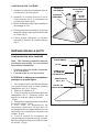
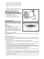
Cet appareil est équipé d’un cordon ayant un câble de mise à la terre avec une fiche de mise à
la terre. La fiche doit être branchée dans une prise de courant correctement installée et mise à
la terre.
ATTENTION - Une mise à la terre incorrecte peut entraîner un risque de décharge électrique.
Consulter un électricien spécialisé si les instructions de mise à la terre ne sont pas tout à fait
compréhensibles ou en cas de doute sur le fait de savoir si l’appareil est correctement relié à la
terre. Ne pas utiliser de prolongation. Si le cordon d’alimentation est trop court, demander à un
électricien agréé d’installer une prise de courant près de l’appareil.
Régler l’alimentation électrique dans l’espace couvert par le conduit décoratif.
Placer la prise femelle à une distance maximum de 33-7/16” (85 cm) de l’endroit où le plomb
sort de la hotte (voir l’illustration ci-contre). S’assurer qu’il n’y ait pas d’interférence avec la
zone de fixation du support ou avec le conduit décoratif (à l’endroit où la gaine touche le mur).
Mettre la fiche dans la prise femelle.
INSTALLATION ELECTRIQUE
Remarque: Ce modèle de hotte doit être
relié à la terre correctement. Cet article
devrait être installé par un électricien
qualifié selon les lois nationales et locales
en matière d’électricité.
INSTRUCTIONS POUR LA MISE A LA
TERRE
Cet appareil doit être relié à la terre. En cas
de court-circuit, la mise à la terre réduit le
risque de décharge électrique en fournissant
un câble permettant au courant d’être dévié.
fig.3
33-7/16"
(85cm)
max

16
7 - 3/4”
(197mm)
fig.6
COLLET DE
REFOULEMENT
DIAMÈTRE DU
CONDUIT 6”
CONNECTEUR
DU CONDUIT
INSTALLATION DU SUPPORT DE
FIXATION DU CARNEAU
CARÉNÉ ET NON CARÉNÉ
1. Assemblez le support de fixation du carneau
en réglant la largeur extérieure comme
indiqué. Fig.5.
2. Centrez soigneusement le support de
fixation directement sur l’emplacement
destine à la hotte.
3. Fixez l’assemblage du support au plafond
au moyen de deux (2) vis de montage de
4,8 x 38 mm et d’ancres murales. Vérifiez
que le support est enfoncé dans le mur
adjacent et qu’il est centré au-dessus de la
hotte.
PREPARE THE HOOD
Remarque: si la hotte est en acier
inoxydable, retirez précautionneusement le
film protecteur des surfaces extérieures et
des carneaux décoratifs avant de terminer
l’installation.
SUPPORT DE
FIXATION DU
CARNEAU
3,9 x 6 mm VIS
D’ASSEMBLAGE À
TÊTE PLATE
INSTALLATION DES ETRIERS
D’ASSEMBLAGE
1. Construisez un cadre en bois pour le mur
dont les vis-pivot ne dépassent pas.
Assurez-vous:
a) que le cadre est centré au-dessus de
l’emplacement de l’installation.
b) la hauteur du cadre permettra que les
étriers d’assemblage soient fixés au
cadre en respectant les dimensions
indiquées.
2. Après avoir terminé la surface du mur, fixez
les étriers d’assemblage au cadre en
respectant les dimensions qui sont
indiquées.
Note:
- Lorsque le plafon est de 8’, la distance above
cook top is:
- minimum 24”, maximum 28” (pour modèle
avec tuyau d’évacuation)
- minimum 24”, maximum 27” (pour modèle
recyclant l’air)
- Lorsque le plafon est de 9’, la distance above
cook top is:
- minimum 28”, maximum 30” (les prises
d’air du carneau décoratif supérieur
demeurent visibles après l’installation)
CADRE POUR LE MUR
36-3/4"(93,5cm) = si la distance entre la hotte et
le plan de cuisson c’est de 24”(61cm).
42-3/4"(109cm) = si la distance entre la hotte et
le plan de cuisson c’est de 30” (76cm).
fig.4
fig.5
de 36 3/4”(93,5cm) à 42 3/4”(109cm)
au-dessus du plan de cuisson

17
A
CONFIGURATION CARÉNÉE
1. Installez le collet de refoulement dans le
conduit relié à la hotte (fig.6).
2. Attachez un conduit arrondi en acier
d’une longueur de 6" au connecteur du
conduit de la hotte (fig.6).
3. Reliez toutes les sections pour empêcher
le passage de l’air.
4. Placez précautionneusement le carneau
décoratif inférieur dans la partie de la hotte
en retrait (fig.7).
5. Faites glisser lentement le carneau
décoratif à l’intérieur du conduit inférieur
(fig.7).
PRÉPARATION DE LA HOTTE
CONFIGURATION NON CARÉNÉE
Note: The following materials must be
purchased separately for non-ducted
recirculation installations.
• Conduit en aluminium flexible / expansible
de 5" de diamètre
• Foret hélicoïdal de 1/16" de diamètre
ATTENTION: n’utilisez pas de conduits en
plastique ou en métal rigide.
1. Ne comptez pas le collet de refoulement
ni le registre fournis avec la hotte. Installez
l’adaptateur de 5" à 6" (fourni).
2. Mesurer la distance “A”.
3. Fixez le conduit en aluminium flexible à
l’adaptateur de 5". Obstruez toutes les
sections à l’aide du ruban du conduit.
(Fig.8)
4. Assemblez l’espacement de recirculation
au conduit flexible. (Fig.8).
5. Pour créer un espacement de
recirculation, percez trois (3) trous de 1/16"
de diamètre et situés à égale distance les uns
des autres sur le conduit et le connecteur du
conduit. (Fig.8)
6. Fixez le conduit au connecteur de
l’espacement au moyen de trois (3) vis à tôle.
Bouchez toutes les sections à l’aide du ruban
du conduit. (Fig.8)
fig.7
CARNEAU
SUPÉRIEUR
CARNEAU
INFÉRIEUR
PRISES D’AIR
SUPÉRIEURES
VISIBLES
PRISES
D’AIR
SUPÉRIEURES
DISSIMULÉES
ESPACEMENT
(3) VIS
CONDUIT EN
ALUMINIUM
FLEXIBLE DE 5"
ADAPTATEUR
DE 5" À 6"
COLLET DU
VENTILATEUR
fig.8

18
PRÉPARATION DE LA HOTTE
CONFIGURATION NON CARÉNÉE (suite).
8. Placez précautionneusement le carneau
décoratif inférieur dans la partie de la hotte
en retrait (fig.7).
9. Faites glisser lentement le carneau
décoratif à l’intérieur du conduit inférieur.
Remarque: les prises d’air doivent être
tournées vers le haut (fig.7).
10.Fixez l’espacement de recirculation au
carneau supérieur au moyen de quatre (4)
vis à tête fraisée (fig.9).
INSTALLATION DE LA HOTTE
Remarque: la hotte doit être installée par au
moins deux personnes.
1. Soulevez la hotte et placez-la
à l’endroit où elle sera installée.
2. Branchez le cordon
d’alimentation à la prise mura-
le. Faites passer la longueur
de cordon qui dépasse derrière
le carneau.
3. Alignez l’ouverture
rectangulaire située à l’arrière
de la hotte avec le support de
fixation murale. Abaissez
lentement la hotte jusqu’à ce
qu’elle s’emboîte avec le
support. Fig.10
ESPACEMENT
4 VIS À
TÊTE
FRAISÉE
(3.4x15 mm)
CARNEAU
SUPÉRIEUR
fig.9
fig.10
VIS
D’ASSEMBLAGE
(4.8x38mm)
TROU
RECTANGULAIRE
VIS DE REGLAGE EN
HAUTEUR (3.9x9.5mm)
PLANCHE DE BOIS POUR
L'ADAPTATION
ETRIERE
fig.11
ATTACHEZ LE CONDUIT DECORATIF A
L’ÉTRIER DE SUPPORT AU MOYEN DES
VIS (3.9x9.5mm)
4. Mettez la hotte.
Les vis de réglage en hauteur permettent de régler
verticalement.
Fixez votre hotte avec des vis d’assemblage
(4.8x38mm). Utilisez des chevilles pour mur à sec,
qui vous sont fournies, si vous ne trouvez pas les
vis-pivot ou le cadre.
Niveau et fixez-la au moyen de deux (2) vis
(4.8x38mm) de montage. Si vous ne disposez pas
de poteaux de cloison ni d’armature, utilisez les
ancres murales fournies. Fig.10
5. Soulevez le carneau supérieur jusqu’à ce que ses
trous soient alignés avec les trous du support de
fixation du carneau (situé au plafond). Fig.11
6. Fixez le carneau au moyen de deux (2) vis de
montage (3.9x9.5mm). Fig.11
VIS
D’ASSEMBLAGE
(4.8x38mm)

19
FILTRE ANTI-GRAISSE
FILTRES VERSION
RECYCLANT L’AIR
fig.12
fig.13
Filtres version recyclant l’air
Les filtres version recyclant l’air l’air doivent être remplacés tous les 6 mois. Faites tourner les
filtres afin de les enlever et de les remettre.
Nettoyage de votre hotte
L’acier inoxydable est une des matières les plus faciles à nettoyer. Un entretien de temps en
temps permettra de le conserver en parfait état. Conseils pour le nettoyage:
• Eau chaude et savon ou détergent est tout ce qui est normalement nécessaire.
• Après chaque nettoyage, rincez bien à l’eau claire. Essuyez avec un chiffon propre et doux
afin d’éviter les taches d’eau.
• Si des décolorations ou des dépôts persistent, utilisez un nettoyant domestique non abrasif
ou de la poudre pour l’acier inoxydable et un peu d’eau et un chiffon doux.
• Dans les cas difficiles, utilisez une éponge en plastique ou une brosse douce avec du
nettoyant et de l’eau. Frottez légèrement en suivant la direction du polissage ou du “grain” de
l’acier inoxydable. Evitez de frotter trop fort afin de ne pas abîmer la surface.
• NE LAISSEZ PAS les taches trop longtemps.
• N’UTILISEZ PAS de laines d’acier ordinaires ou des brosses en acier. Des débris d’acier
pourraient adhérer à la surface et causer de la rouille.
• NE PERMETTEZ PAS que des solutions salées, des désinfectants, des blanchissants ou
des produits nettoyants restent en contact avec l’acier pendant longtemps. Beaucoup de
ces produits contiennent des produits chimiques qui pourraient causer des dommages. Rincez
à l’eau immédiatement s’ils entrent en contact et essuyez avec un chiffon humide.
Les surfaces peintes doivent être nettoyées avec de l’eau tiède additionnée d’un détergent
doux seulement.
ASSEMBLAGE DES FILTRES
VERSION RECYCLANT L’AIR
1. Les filtres version recyclant l’air
(B03300487) sont fourni.
2. Placez les filtres au-dessus du ventilateur.
Grâce à un mouvement rotatif, fixez les
filtres à leur place.
ENTRETIEN
Un bon entretien de votre hotte garantira une
excellente performance.
Filtre anti-graisse
Le filtre anti-graisse doit être nettoyé
fréquemment. Utilisez une solution contenant
un détergent tiède. Le filtre anti-graisse peut
être lavé au lave-vaisselle.
Enlevez le filtre en le poussant vers l’arrière
de votre hotte et en le faisant tourner vers le
bas.

20
fig.14
LIGHT
SWITCH
PILOT
LAMP
BLOWER
SWITCH
01 01234
fig.15
FONCTIONNEMENT
Commandes
La hotte peut être manœuvrée à l’aide des
curseurs situés sous la partie inférieure de
la hotte.
L’interrupteur de la lumière allume et éteint
les lampes.
L’interrupteur du ventilateur permet de
sélectionner la vitesse de marche du
moteur. Position 0: moteur éteint.
Le voyant lumineux s’allume quand le
ventilateur fonctionne.
HEAT SENTRY
MC
Votre hotte est munie d’un thermostat HEAT SENTRY
MC
. Ce thermostat est un dispositif qui
actionnera ou augmentera la vitesse du ventilateur s’il détecte une chaleur excessive au-
dessus de la surface de cuisson.
1) Si le ventilateur n’est pas en marche - il actionnera le ventilateur en haute vitesse.
2) Si le ventilateur fonctionne en basse vitesse - le ventilateur tournera en haute vitesse.
Lorsque la température revient à la normale, le ventilateur retourne à sa vitesse d’origine.
AVERTISSEMENT
Le thermostat HEAT SENTRY
MC
peu actionner la hotte même si la hotte est arrêtée.
Si tel est le cas, il est impossible de l’arrêter avec l’interrupteur. Si vous devez arrêter
le ventilateur, faites-le à partir du panneau électrique principal.
AMPOULES
Ce modèle de hotte veut 2 lampes type 40
Watt (fournies).
AVANT DE PROCÉDER À QUELCONQUE
OPÉRATION, DÉBRANCHEZ L’APPAREIL.
Pour changer les ampoules:
1. Enlever la vis fixant le système
d’éclairage.
2. Pour enlever le plafonnier, tirer-le vers le
bas.
3. Remplacer par un tube ayant les mêmes
caractéristiques. ATTENTION: LE TUBE
PEUT ETRE CHAUDE!
fig.16
La page est en cours de chargement...
La page est en cours de chargement...
La page est en cours de chargement...
La page est en cours de chargement...
La page est en cours de chargement...
La page est en cours de chargement...
La page est en cours de chargement...
La page est en cours de chargement...
La page est en cours de chargement...
La page est en cours de chargement...
La page est en cours de chargement...
La page est en cours de chargement...
La page est en cours de chargement...
La page est en cours de chargement...
La page est en cours de chargement...
La page est en cours de chargement...
-
 1
1
-
 2
2
-
 3
3
-
 4
4
-
 5
5
-
 6
6
-
 7
7
-
 8
8
-
 9
9
-
 10
10
-
 11
11
-
 12
12
-
 13
13
-
 14
14
-
 15
15
-
 16
16
-
 17
17
-
 18
18
-
 19
19
-
 20
20
-
 21
21
-
 22
22
-
 23
23
-
 24
24
-
 25
25
-
 26
26
-
 27
27
-
 28
28
-
 29
29
-
 30
30
-
 31
31
-
 32
32
-
 33
33
-
 34
34
-
 35
35
-
 36
36


Broan RM503004 Manuel utilisateur
- Catégorie
- Hottes
- Taper
- Manuel utilisateur
dans d''autres langues
- español: Broan RM503004 Manual de usuario
Documents connexes
-
Broan RM503623 Manuel utilisateur
-
Broan RM659004 Guide d'installation
-
-
Broan RMPE7004 Guide d'installation
-
Rangemaster RM50000 Series Manuel utilisateur
-
Broan RM503001 Le manuel du propriétaire
-
-