Sauder Parklane 423107 Assemly Instructions
- Taper
- Assemly Instructions

sauder.com
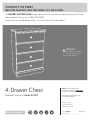
4-Drawer Chest
Parklane Collection | Model 423107
NOTE: THIS INSTRUCTION
BOOKLET CONTAINS IMPORTANT
SAFETY INFORMATION.
PLEASE READ AND KEEP FOR
FUTURE REFERENCE.
English pg 1-18
Français pg 19-21
Español pg 22-24
Lot # 529357 05/14/19
Purchased: __________________
sauder.com
CONTACT US FIRST
BEFORE MAKING ANY RETURNS TO THE STORE.
Share your journey!
sauder.com
CONTACT US FIRST
BEFORE MAKING ANY RETURNS TO THE STORE.
Visit sauder.com/service to order replacement parts, view video assembly tips, or chat with a live rep.
Prefer the phone? Give us a ring at
1-800-523-3987.
Customer Service is available Monday-Friday - 9 a.m. to 5:30 p.m. EST (except holidays)
WARNING
CHOKING HAZARD - Small Parts
Not for children under 3 years.
Adult assembly required.

Part Identifi cation
Hardware Identifi cation
Assembly Steps
Français
Español
Safety
Warranty
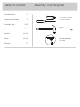
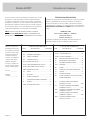
No. 2 Phillips Screwdriver
Tip Shown Actual Size
Table of Contents Assembly Tools Required
Skip the power trip.
This time.
3
4
5-18
19-21
22-24
25-26
27
423107 www.sauder.com/servicesPage 2
Hammer
Not actual size

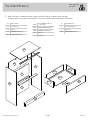
å While not all parts are labeled, some of the parts will have a label or an inked letter on the edge
to help distinguish similar parts from each other. Use this part identifi cation to help identify similar parts.
Part Identifi cation
Now you know
our ABCs.
A2 RIGHT END (1)
B2 LEFT END (1)
C3 TOP (1)
D2 DRAWER FRONT (4)
D175 DRAWER BACK (4)
D257
LEFT DRAWER SIDE (4)
- 1 with label
D262 RIGHT DRAWER SIDE (4)
D981 DRAWER BOTTOM (4)
E2 BASE (1)
F BRACE (1)
H UPPER BACK (1)
J TOP MOLDING (1)
K BACK (2)
M64 DRAWER BRACE (4)
A2
B2
C3
D2
E2
F
K
K
H
J
M64
D175
D257
D262
D981
423107www.sauder.com/services
Page 3

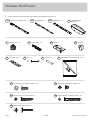
å Screws are shown actual size. You may receive extra hardware with your unit.
Hardware Identifi cation
423107 www.sauder.com/servicesPage 4
35AA
UNIVERSAL CABINET RAIL - 8
35AC
DRAWER RIGHT - 4
35AD
DRAWER LEFT - 4
FELT DISC CARD - 1
1M
GOLD 1" MACHINE SCREW - 4
50S
BLACK 9/16" LARGE HEAD SCREW - 29
1S
SILVER 1-1/8" FLAT HEAD SCREW - 3
10S
HINGE - 2
16H
3S
GOLD 5/16" FLAT HEAD SCREW - 32
METAL PIN - 2
1R
KNOB - 4
5K
NAIL - 17
1N
HIDDEN CAM - 18
1F
CAM DOWEL - 18
2F
30S
BLACK 1-9/16" FLAT HEAD SCREW - 20
DRAWER FRONT
BRACKET - 4
9G
FURNITURE TIPPING RESTRAINT KIT - 1
97

Step 1
Look for this icon. It means a
video assembly tip is available at
www.sauder.com/services/tips
å
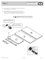
Assemble your unit on a carpeted fl oor or on the empty carton to
avoid scratching your unit or the fl oor.
å
Push eighteen HIDDEN CAMS (1F) into the ENDS (A2 and B2),
BRACE (F), BACKS (K), and DRAWER BRACES (M64). Then, insert
the metal end of a CAM DOWEL (2F) into each HIDDEN CAM.
423107www.sauder.com/services
Page 5
A2
B2
F
M64 x 4
K x 2
Do not tighten the HIDDEN CAMS in this step.
Arrow
1F
2F
(18 used)
Metal end
Insert the metal end of the CAM
DOWEL into the HIDDEN CAM.
The arrow in the HIDDEN
CAM must point toward the
hole in the edge of the board.
Hole

Step 2
423107 www.sauder.com/servicesPage 6
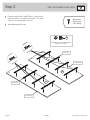
å
Fasten the UNIVERSAL CABINET RAILS* (35AA) to the
ENDS (A2 and B2). Use sixteen GOLD 5/16" FLAT HEAD
SCREWS (3S) through holes #1 and #3.
å
*patent pending glide system
GOLD 5/16" FLAT HEAD SCREW
(16 used in this step)
3S
Glide end
3
2
1
1
2
3
1
2
3
1
2
3
1
2
3
Glide end
VIEW THE DRAWER GLIDE VIDEO
Finished edge
Finished edge
3
3
3
2
2
2
1
1
1
Remember:
Righty tighty.
Lefty loosey.
A2
B2

Step 3
423107www.sauder.com/services
Page 7
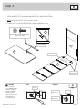
å
Open the FURNITURE TIPPING RESTRAINT KIT (97) and fasten the SAFETY
STRAP to the TOP (C3). Use the provided BLACK 9/16" LARGE HEAD SCREW.
å
NOTE: Position the SAFETY STRAP exactly as shown.
å
Fasten the TOP (C3) to the LEFT END (B2). Tighten two HIDDEN CAMS.
C3
B2
Start Tighten
Arrow
Minimum
190 degrees
Caution
Risk of damage or
injury. HIDDEN CAMS
must be completely
tightened. HIDDEN
CAMS that are not
completely tightened
may loosen, and parts
may separate. To
completely tighten:
Arrow
Maximum
210 degrees
Finished edge
Surface with holes
Surface with
HIDDEN CAMS
C3
Safety strap
97
BLACK 9/16" LARGE HEAD SCREW
(1 used in this step)
These edges
must be even.

Step 4
423107 www.sauder.com/servicesPage 8
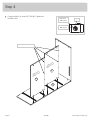
å
Fasten the BACKS (K) to the LEFT END (B2). Tighten four
HIDDEN CAMS.
Arrow
Minimum
190 degrees
Maximum
210 degrees
Surface with
HIDDEN CAMS
Surface with
HIDDEN CAMS
These holes must be here.
B2
K
K

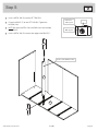
Step 5
423107www.sauder.com/services
Page 9
å
Insert a METAL PIN (1R) into the LEFT END (B2).
å
Fasten the BRACE (F) to the LEFT END (B2). Tighten the
HIDDEN CAM.
å
NOTE: Be sure the METAL PIN in the END inserts into the hole
in the BRACE.
å
Insert a METAL PIN (1R) into the short edge of the BRACE (F).
F
1R
1R
B2
Surface with HIDDEN CAMS
Arrow
Minimum
190 degrees
Maximum
210 degrees

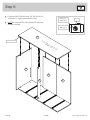
å
Fasten the RIGHT END (A2) to the TOP (C3), BACKS (K),
and BRACE (F). Tighten seven HIDDEN CAMS.
å
NOTE: Be sure the METAL PIN in the BRACE inserts into
the hole in the END.
Step 6
423107 www.sauder.com/servicesPage 10
Arrow
Minimum
190 degrees
Maximum
210 degrees
A2
K
k
C3
Surface without HIDDEN CAMS
Finished edge
F

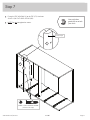
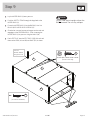
Step 7
423107www.sauder.com/services
Page 11
å
Fasten the TOP MOLDING (J) to the TOP (C3). Use three
SILVER 1-1/8" FLAT HEAD SCEWS (10S).
å
NOTE: Do not overtighten the screws.
SILVER 1-1/8" FLAT HEAD SCREW
(3 used in this step)
10S
J
J
Curved edge
C3
Now might be a
good time to refresh
your drink.

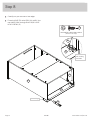
å
Carefully turn your unit onto its front edges.
å
Fasten the BASE (E2) to the ENDS (A2 and B2). Use
two HINGES (16H) and eight BLACK 9/16" LARGE
HEAD SCREWS (1S).
Step 8
423107 www.sauder.com/servicesPage 12
16H
E2
16H
A2
B2
B2
E2
Curved edge
The BASE
will overhang
the ENDS.
BLACK 9/16" LARGE HEAD SCREW
(8 used in this step)
1S

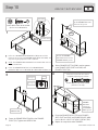
Step 9
423107www.sauder.com/services
Page 13
å
Lay the UPPER BACK (H) over your unit.
å
Push the SAFETY STRAP through the large hole in the
UPPER BACK (H).
å
Fasten the UPPER BACK (H) to the BACK (K). Use fi ve
BLACK 9/16" LARGE HEAD SCREWS (1S).
å
Check to be sure you have equal margins on the side and
top edges of the UPPER BACK (H). Finish fastening the
UPPER BACK (H) to your unit using the NAILS (1N).
å
Peel a FELT DISC from the FELT DISC CARD (1M) and stick
them on the ENDS (A2 and B2) and BASE (E2) as shown.
Do not stand the unit upright without the
BACK fastened. The unit may collapse.
Caution
NAIL
(17 used for the BACK)
1N
Push the
SAFETY STRAP
through the hole.
BLACK 9/16" LARGE HEAD SCREW
(5 used in this step)
1S
H
K
A2
B2
E2
1M

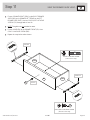
Step 10
423107 www.sauder.com/servicesPage 14
VIEW THE T-SLOT BOX VIDEO
1
3
2
4
å
Pull a set of DRAWER FRONT BRACKETS (9G) apart and slide
them into the grooves in the DRAWER SIDES (D257 and D262). You
may need to gently tap them in with a hammer.
å
NOTE: The DRAWER FRONT BRACKETS are marked "RH" and "LH"
for easy identifi cation.
å
Fasten the DRAWER FRONT (D2) to the DRAWER FRONT
BRACKETS (9G). Use four BLACK 9/16" LARGE HEAD SCREWS (1S).
å
Slide a DRAWER BOTTOM (D981) into the grooves
in the DRAWER SIDES (D257 and D262) and
DRAWER FRONT (D2).
å
Fasten the DRAWER BRACE (M64) to the DRAWER
FRONT (D2). Tighten one HIDDEN CAM.
å
Fasten the DRAWER BACK (D175) to the DRAWER
SIDES (D257 and D262) and DRAWER BRACE (M64).
Use fi ve BLACK 1-9/16" FLAT HEAD SCREWS (30S).
å
Repeat this step for the other DRAWERS.
BLACK 9/16" LARGE HEAD SCREW
(16 used for the BRACKETS)
1S
D262
D981
D257
D262
D175
D257
D262
D257
D2
D2
M64
M64
D2
Be sure the DRAWER
BOTTOM inserts into the
DRAWER FRONT groove.
Be sure the
DRAWER
BOTTOM
inserts into
the DRAWER
BACK groove.
With the palm of your hand,
tap the DRAWER BOTTOM
down into the groove.
30S
Start each screw a few turns before
completely tightening any of them.
BLACK 1-9/16" FLAT HEAD SCREW
(20 used in this step)
Unfi nished surface
Surface with
HIDDEN CAM
Arrow
Minimum
190 degrees
Maximum
210 degrees
9G
Push down
(4 sets used)

Step 11
423107www.sauder.com/services
Page 15
å
Fasten a DRAWER RIGHT (35AC) to the RIGHT DRAWER
SIDE (D262) and a DRAWER LEFT (35AD) to the LEFT
DRAWER SIDE (D257). Use four GOLD 5/16" FLAT HEAD
SCREWS (3S) through holes #1 and #2.
å
NOTE: The glides are not intended to rotate.
å
Fasten a KNOB (5K) to the DRAWER FRONT (D2). Use a
GOLD 1" MACHINE SCREW (50S).
å
Repeat this step for the other drawers.
1
2
1
2
GOLD 5/16" FLAT HEAD SCREW
(16 used in this step)
3S
VIEW THE DRAWER GLIDE VIDEO
Glide end
Glide end
5K
GOLD 1" MACHINE SCREW
(4 used in this step)
50S
(4 used)
D262
D257
D2

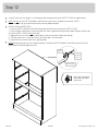
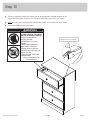
Step 12
423107 www.sauder.com/servicesPage 16
å
Carefully stand your unit upright in its fi nal location. We recommend using the SAFETY STRAP for added stability.
å
NOTE: Do not turn the SAFETY DRYWALL ANCHOR into a wall stud. If you prefer to fasten the SAFETY
STRAP to a wall stud, go to your local hardware store for proper hardware.
å
INSTALLATION INSTRUCTIONS:
1. Insert the SAFETY DRYWALL ANCHOR through the WASHER and the end of the SAFETY STRAP.
2. Using a Phillips screwdriver or a hand drill, press the screw slightly onto the drywall just below the top surface of your
unit so the SAFETY STRAP will not be visible.
3. Apply pressure; turn the screw until a pilot hole is made and the nylon sheath slips through.
4. Turn the screw until it is fl ush against the wall and you feel a fi rm resistance.
5. Continue to turn until the screw starts spinning freely.
å
NOTE: Before moving your unit to a di erent location, unscrew the SAFETY DRYWALL ANCHOR from your wall. The
nylon sheath will remain behind your wall.
Pro Tip: Lift with your
legs. And, you know,
your arms.
Safety
drywall
anchor
Safety strap
Washer

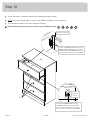
Step 13
423107www.sauder.com/services
Page 17
å
To insert the drawers into your unit, tip the front of the drawer down and drop the glides on the
drawer behind the glides on the unit. Lift the front of the drawer up and slide it into the unit.
å
NOTE: Be sure to insert the drawer with the WARNING LABEL into the top of the unit as shown.
å
See the next step for drawer adjustments.
WA
R
N
IN
G
AV
E
RT
IS
S
E
M
E
N
T
ADV
E
RT
E
N
C
IA
o
ccur from
fur
ni
ture tip
-
over.
T
o he
lp
p
reven
t tip-
o
ve
r:
• Insta
ll tip
-
over restrain
t p
r
ovid
e
d.
• P
lace h
e
aviest ite
m
s
in th
e l
owe
r
drawers.
•
D
o
n
o
t
s
e
t
T
V
’s
o
r
o
t
h
e
r
h
e
a
v
y
o
b
je
c
t
s
o
n
t
o
p
o
f
t
h
is
p
r
o
d
u
c
t
, u
n
le
s
s
t
h
e
p
r
o
d
u
c
t
is
d
ra
wers, d
oors
, or sh
elve
s.
• N
eve
r o
pen
m
ore tha
n o
ne
d
ra
wer at
a
time.
U
se
o
f tip-
o
v
er res
train
ts m
ay on
ly
r
educ
e, b
ut no
t e
lim
ina
t
e, the risk o
f
tip-ove
r.
Th
is is a
perm
a
ne
nt la
be
l. Do not re
m
o
ve
!
é
cra
se
m
e
nt p
euve
nt su
rvenir si le
m
ob
ilier
b
ascule. Pour p
révenir le b
a
scule
m
e
nt :
• Installe
r le dis
pos
itif a
nti-ba
scu
le
m
en
t fo
urni.
• P
lace
r les
a
rticles plus
lourds
dan
s les
tiro
irs
infé
rie
ur
s
.
• N
e pa
s m
e
ttre d
e télév
iseur o
u
d’autre o
bjets
lou
rd
s s
ur le
dess
u
s d
e ce m
eu
bl
e,
s
au
f s
i le
• N
e
jam
a
is o
uvrir p
lus
d’un tiro
ir à
la
fo
i
s.
L’utilis
atio
n de
dispos
itifs anti-basc
ulem
ent
p
eut réd
uire le
ris
que de bascu
lem
e
n
t
,
ma
is
p
as l’é
lim
ine
r.
C
ette étiq
u
ette
e
st p
erm
an
en
t
e
. N
e pas
l’enle
ver!
pue
den ocurrir p
or el v
olcar de
lo
s
mu
eble
s
.
Para ayuda
r a pre
ven
ir q
ue
se
volq
ué
:
• Ins
talar la co
nten
ción
b
rinda
da
p
a
ra ev
itar
que s
e vo
lq
u
é.
• C
o
lo
que los
a
r
tículos m
ás pe
sa
do
s en
los
cajo
nes inferio
re
s.
• N
o co
lo
que
t
elevisores
u o
tros
ob
jetos
pes
ad
os en la p
a
rte superior d
e este prod
u
ct
o
,
diseñ
a
do
para
aco
m
o
darlo
s.
• N
un
ca perm
ita que
los
niño
s se
su
b
an
o
se
• Nun
ca a
bra
m
ás
d
e un cajón
a la
v
ez.
El u
so
de
la
c
ontenc
ión p
ued
e
solam
ent
e
E
sta
es una etiq
ueta perm
anent
e. ¡N
o remover!
Place the glide on the SLIDE
behind the glide on the RAIL.
WARNING
Children have died from
furniture tipover. To reduce
the risk of furniture tipover:
• ALWAYS install tipover
restraint provided.
• NEVER put a TV on this
product.
• NEVER allow children to
stand, climb, or hang on
drawers, doors, or shelves.
• NEVER open more than one
drawer at a time.
• Place heaviest items in the
lowest drawers.
This is a permanent label.
Do not remove!
1/19 526119

Step 14
423107 www.sauder.com/servicesPage 18
WA
R
N
IN
G
AV
E
RT
IS
S
E
M
E
N
T
ADV
E
R
T
E
N
C
I
A
oc
cu
r fr
om
furn
iture tip-
over. T
o help
pre
ve
nt
tip
-
o
ve
r:
• Install tip
-
over restrain
t pr
ovided.
• P
lace he
aviest item
s
in the
l
o
wer
drawe
rs.
•
D
o
n
o
t
s
e
t
T
V
’s o
r
o
t
h
e
r
h
e
a
v
y
o
b
je
c
t
s
o
n
t
o
p
o
f
t
h
i
s
p
r
o
d
u
c
t
,
u
n
le
s
s
th
e
p
r
o
d
u
c
t
i
s
drawers, doors, or shelve
s.
•
N
ever
open m
o
re th
an o
ne dra
wer at
a time.
Us
e of tip-
ove
r r
estraints m
ay only
reduce, but not elim
ina
t
e, the risk
o
f
tip-ove
r
.
T
his is
a perm
a
nent lab
el. D
o
not
rem
o
ve!
écr
as
em
ent
peuvent su
rvenir
si le m
ob
ilie
r
bas
cu
l
e. Pour p
révenir le b
asculem
ent :
• In
sta
ller le dispo
sitif an
ti-bas
culem
ent
fo
urni.
• P
lacer les a
rticles plus lo
urds da
n
s les tiroirs
inférie
ur
s
.
• Ne pas
m
e
ttre
de télé
viseur o
u
d
’autre objet
s
lou
rds
sur le dessu
s de ce
m
eub
l
e
,
sau
f si le
•
Ne jam
ais
o
uv
rir plus
d’un
tiroir à la
foi
s.
L’utilisat
ion de
d
isp
os
itifs an
ti-bascule
me
nt
p
eut réd
uire le
risq
ue de bascule
me
nt
,
m
ais
p
as l
’élim
in
e
r.
Cett
e étiqu
ette est p
erm
ane
nt
e. Ne
pas
l’enle
ver!
pued
e
n ocurr
ir po
r e
l volcar de lo
s m
ue
ble
s
.
P
a
ra a
yudar a
p
r
eve
n
ir que se
volqué
:
• Instalar la co
ntención
brind
a
da p
ara
evitar
que s
e volqu
é.
• Coloque
los a
r
tíc
u
los m
ás
p
esa
dos e
n
los
cajon
e
s inferiore
s.
• No co
loque tele
viso
res
u otros ob
jet
os
pe
sad
os
en la
pa
rt
e su
p
erior d
e este p
rod
uct
o
,
d
iseñad
o pa
ra
aco
m
o
darlo
s.
• Nunc
a p
erm
ita qu
e lo
s niño
s se s
uban
o se
• Nunca a
bra
m
ás
de u
n cajón a
la
vez
.
E
l us
o d
e la
conte
nción
p
ue
de sola
m
ente
Es
ta
es una e
tiqueta perm
an
ent
e. ¡No
rem
ov
er!
å
Drawer adjustments, if needed, can be made by following the diagrams below.
å
NOTE: Please read the back pages of the instruction booklet for important safety information.
å
This completes assembly. Clean with a damp cloth. Wipe dry.
35 lbs.
35 lbs.
40 lbs.
Adjust the
drawer up
or down.
Drawer Slide
To adjust the DRAWER FRONTS using
the DRAWER SLIDE, loosen the SCREW
in the slotted hole, adjust the drawer up or
down as needed, then tighten the SCREW.
To adjust the DRAWER FRONTS using the
DRAWER FRONT BRACKETS, loosen these
SCREWS, adjust the DRAWER FRONT up or
down as needed, then tighten the SCREWS.
Drawer Side
Drawer Front
Drawer front bracket
And to celebrate, why not share your success story at Walmart.com or

A l’usage exclusif du
Canada Noter la date
d’achat de cet élément
et conserver le livret
pour future référence.
Pour contacter Sauder
en ce qui concerne cet
élément, faire référence
au numéro de lot et
numéro de modèle en
appelant notre numéro
sans frais.
Lot nº : ____________
Date de
l’achat: ____________
LISTE DE PIÈCES
REFERENCE DESCRIPTION QUANTITÉ
LISTE DE PIÈCES
REFERENCE DESCRIPTION QUANTITÉ
NOUS SOMMES LA POUR VOUS AIDER!
Nous faisons de notre mieux pour nous assurer que votre meuble
arrive dans d’excellentes conditions. Nos représentants du service
Clientèle sont aimables et prêts à vous aider au cas où une pièce
aurait été endommagée ou manquerait (ou si vous aviez besoin
d’aide pour l’assemblage). NE RAMENEZ PAS LE MEUBLE AU
MAGASIN. Au Canada, composez ce numéro d’appel gratuit:
1-800-523-3987
Du lundi au vendredi, de 9 heures du matin à
5:30 heures du soir (horaire Côte Est)
(sauf jours fériés)
Si une pièce a besoin d’être remplacée, la pièce de remplacement
sera envoyée dans les 48 heures. (Sauf week-ends et jours fériés)
Utilisez les instructions d’assemblage en français avec les
schémas étape par étape du manuel d’instruction en anglais.
Chaque étape en français correspond à la même étape
en anglais. La pièce devant être attachée à l’élément est
représentée en gris sur les schémas de chaque étape pour plus
de précision. Comparer la “Liste de pièces” ci-dessous avec
la “PART IDENTIFICATION” du manuel en anglais pour vous
familiariser avec les pièces avant l’assemblage.
REMARQUE : CE MANUEL D’INSTRUCTIONS CONTIENT
D’IMPORTANTES INFORMATIONS RELATIVES À LA SÉCURITÉ.
À LIRE ET CONSERVER POUR TOUTE RÉFÉRENCE FUTURE.
35AA
GLISSIÈRE D'ÉLÉMENT UNIVERSELLE
....8
35AC TIROIR DROIT ...........................................................4
35AD TIROIR GAUCHE .....................................................4
9G CONSOLE DE DEVANT DE TIROIR .........4
1F EXCENTRIQUE ESCAMOTABLE .............18
2F CHEVILLE D'EXCENTRIQUE ......................18
16H CHARNIÈRE ................................................................2
5K BOUTON .......................................................................4
1M FICHE DE TAMPONS EN FEUTRE.............1
1N CLOU .............................................................................17
1R GOUPILLE EN MÉTAL ........................................2
97 KIT DE RETENUE ANTI-BASCULEMENT
POUR MOBILIER......................................................1
1S VIS TÊTE LARGE 14 mm NOIRE ............29
3S VIS TÊTE PLATE 8 mm DORÉE ............. 32
10S VIS TÊTE PLATE 28 mm ARGENTÉE ....3
30S VIS TÊTE PLATE 40 mm NOIRE ...........20
50S VIS À MÉTAUX 25 mm DORÉE ..................4
A2 EXTRÉMITÉ DROITE .................................................1
B2 EXTRÉMITÉ GAUCHE ..............................................1
C3 DESSUS ..............................................................................1
D2 DEVANT DE TIROIR .................................................4
D175 ARRIÈRE DE TIROIR .................................................4
D257 CÔTÉ GAUCHE DE TIROIR................................4
D262 CÔTÉ DROIT DE TIROIR ......................................4
D981 FOND DE TIROIR .......................................................4
E2 BASE .....................................................................................1
F ENTRETOISE ..................................................................1
H ARRIÈRE SUPÉRIEUR ..............................................1
J MOULURE DE DESSUS .........................................1
K ARRIÈRE ............................................................................2
M64 ENTRETOISE DE TIROIR ......................................4
Commode 4 TiroirsModèle 423107
423107www.sauder.com/services
Page 19

ÉTAPE 7
Fixer la MOULURE DE DESSUS (J) au DESSUS (C3). Utiliser trois
VIS TÊTE PLATE 28 mm ARGENTÉES (10S).
REMARQUE : Ne pas trop serrer les vis.
ÉTAPE 8
Avec précaution, retourner l'élément sur ses chants avant.
Fixer la BASE (E2) aux EXTRÉMITÉS (A2 et B2). Utiliser deux
CHARNIÈRES (16H) et huit VIS TÊTE LARGE 14 mm NOIRES (1S).
ÉTAPE 6
Fixer l'EXTRÉMITÉ DROITE (A2) au DESSUS (C3), aux ARRIÈRES (K)
et à l'ENTRETOISE (F). Serrer sept EXCENTRIQUES ESCAMOTABLES.
REMARQUE : S'assurer de bien insérer la GOUPILLE EN MÉTAL
située sur l’ENTRETOISE dans le trou dans l’EXTRÉMITÉ.
ÉTAPE 5
Insérer une GOUPILLE EN MÉTAL (1R) dans l'EXTRÉMITÉ GAUCHE (B2).
Fixer l'ENTRETOISE (F) à l'EXTRÉMITÉ GAUCHE (B2). Serrer
l’EXCENTRIQUE ESCAMOTABLE.
REMARQUE : S'assurer de bien insérer la GOUPILLE EN MÉTAL
située sur l’EXTRÉMITÉ dans le trou dans l’ENTRETOISE.
Insérer une GOUPILLE EN MÉTAL (1R) dans le chant court
de l'ENTRETOISE (F).
ÉTAPE 3
Ouvrir le KIT DE RETENUE ANTI-BASCULEMENT POUR
MOBILIER (97) et fi xer la SANGLE DE SÉCURITÉ au DESSUS (C3).
Utiliser la VIS TÊTE LARGE 14 mm NOIRE fourni.
REMARQUE : Placer la SANGLE DE SÉCURITÉ exactement
comme l'indique le schéma.
Fixer le DESSUS (C3) à l'EXTRÉMITÉ GAUCHE (B2). Serrer deux
EXCENTRIQUES ESCAMOTABLES.
ÉTAPE 2
Fixer les GLISSIÈRES D'ÉLÉMENT UNIVERSELLES* (35AA) aux
EXTRÉMITÉS (A2 et B2). Utiliser seize VIS TÊTE PLATE 8 mm
DORÉES (3S) à travers les trous nº 1 et nº 3.
*système de coulisse en instance de brevet
ÉTAPE 1
Ne pas serrer les EXCENTRIQUES ESCAMOTABLES dans cette étape.
Assembler l'élément sur un sol à moquette ou sur le carton vide
pour éviter d'endommager l'élément ou le sol.
Enfoncer dix-huit EXCENTRIQUES ESCAMOTABLES (1F) dans les
EXTRÉMITÉS (A2 et B2), l'ENTRETOISE (F), les ARRIÈRES (K) et
les ENTRETOISES DE TIROIR (M64).
Ensuite, insérer l'extrémité en métal de la CHEVILLE
D'EXCENTRIQUE (2F) dans chaque EXCENTRIQUE ESCAMOTABLE.
423107 www.sauder.com/servicesPage 20
ÉTAPE 9
Attention: Ne pas relever l'élément dans sa position verticale
avant d'avoir fi xé l’ARRIÈRE. L'élément risque de s'e ondrer.
Placer l’ARRIÈRE SUPÉRIEURE (H) sur l'élément.
Enfoncer la SANGLE DE SÉCURITÉ dans le gros trou dans
l'ARRIÈRE SUPÉRIEUR (H).
Fixer l’ARRIÈRE SUPÉRIEUR (H) à l'ARRIÈRE (K). Utiliser cinq VIS
TÊTE LARGE 14 mm NOIRES (1S).
Vérifi er pour s’assurer des marges égales sur les côtés latéraux et
supérieur de l'ARRIÈRE SUPÉRIEUR (H). Finir de fi xer l'ARRIÈRE
SUPÉRIEUR (H) à l'élément à l'aide des CLOUS (1N).
Séparer un TAMPON EN FEUTRE de la FICHE AVEC TAMPONS
EN FEUTRE (1M) et les coller sur les EXTRÉMITÉS (A2 et B2) et la
BASE (E2) comme l'indique le schéma.
ÉTAPE 4
Fixer les ARRIÈRES (K) à l'EXTRÉMITÉ GAUCHE (B2). Serrer
quatre EXCENTRIQUES ESCAMOTABLES.
La page est en cours de chargement...
La page est en cours de chargement...
La page est en cours de chargement...
La page est en cours de chargement...
La page est en cours de chargement...
La page est en cours de chargement...
La page est en cours de chargement...
La page est en cours de chargement...
-
 1
1
-
 2
2
-
 3
3
-
 4
4
-
 5
5
-
 6
6
-
 7
7
-
 8
8
-
 9
9
-
 10
10
-
 11
11
-
 12
12
-
 13
13
-
 14
14
-
 15
15
-
 16
16
-
 17
17
-
 18
18
-
 19
19
-
 20
20
-
 21
21
-
 22
22
-
 23
23
-
 24
24
-
 25
25
-
 26
26
-
 27
27
-
 28
28


Sauder Parklane 423107 Assemly Instructions
- Taper
- Assemly Instructions
dans d''autres langues
- English: Sauder Parklane 423107
- español: Sauder Parklane 423107
Documents connexes
-
Sauder 412301 Mode d'emploi
-
-
-
-
-
-
-
-
-