
AGA Marvel
1260 E. VanDeinse St.
Greenville MI 48838
Toll free phone: 800-223-3900
Fax: 616-754-9690
www.agamarvel.com
THANK YOU for purchasing this high-quality product. If you should experience a problem not covered
in TROUBLESHOOTING, please visit our website at www.agamarvel.com for additional information. If
you still need assistance, call us at 1-800-223-3900.
You will need your model and serial number, located on the inside wall of the refrigerator compart-
ment.
AMPROFD23C Refrigerator User Instructions

2
NOTE
NOTE
!
CAUTION
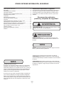
Important Safety Instructions
Warnings and safety instructions appearing in this guide
are not meant to cover all possible conditions and situa-
tions that may occur. Common sense, caution, and care
must be exercised when installing, maintaining, or operat-
ing this appliance.
Recognize Safety Symbols,
Words, and Labels.
!
WARNING
WARNING-You can be killed or seriously injured if
you do not follow these instructions.
CAUTION-Hazards or unsafe practices which could re-
sult in personal injury or property / product damage.
NOTE-Important information to help assure a problem
free installation and operation.
State of California Proposition 65 Warnings:
WARNING: This product contains one or more chemicals
known to the State of California to cause cancer.
WARNING: This product contains one or more chemicals
known to the State of California to cause birth defects or
other reproductive harm..
Table of Contents
Table of contents ................................................................2
Safety .................................................................................2
Unpacking your appliance ..................................................3
Electrical information ..........................................................4
Feature overview ................................................................5
Product dimensions ............................................................6
Installation ..........................................................................7
Removing the doors ..........................................................11
Connecting the water supply .............................................13
Controls ............................................................................14
Ice maker ..........................................................................16
Storage features ...............................................................17
Storing food and saving energy .......................................21
Normal operating sounds .................................................22
Changing water and air lters............................................23
Care and cleaning ............................................................25
Replacing LED lights ........................................................27
Solutions to common problems ........................................28
Warranty ...........................................................................31
FINDING INFORMATION AND SAFETY
CFC/HCFC DISPOSAL
Your old refrigerator may have a cooling system that used
CFCs or HCFCs (chlorouorocarbons or hydrochlorouo-
rocarbons). CFCs and HCFCs are believed to harm strato-
spheric ozone if released to the atmosphere. Other refriger-
ants may also cause harm to the environment if released to
the atmosphere.
If you are throwing away your old refrigerator, make sure
the refrigerant is removed for proper disposal by a qualied
technician. If you intentionally release refrigerant, you may
be subject to nes and imprisonment under provisions of
environmental legislation.
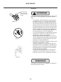
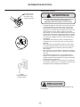
!
CAUTION
• Do not store or use gasoline or other ammable liquids
near this or any other appliance. Read product labels
for warnings regarding ammability and other hazards.
• Do not operate the refrigerator in the presence of ex-
plosive fumes.
• Avoid contact with any moving parts of the automatic
ice maker.

3
!
CAUTION
Help Prevent Tragedies
Child entrapment and suffocation are not problems of the
past. Junked or abandoned refrigerators are still dangerous
- even if they sit out for "just a few hours".
If you are getting rid of your old refrigerator, please follow
the instructions below to help prevent accidents.
Before you throw away your old refrigerator or freezer:
• Take off the doors or remove the drawers.
• Leave the shelves in place so children may not easily
climb inside.
NOTE
!
CAUTION
!
CAUTION
!
WARNING
EXCESSIVE WEIGHT HAZARD
Use two or more people to move product.
Failure to do so can result in personal injury.
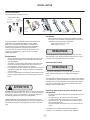
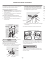
Remove Interior Packaging
Your appliance has been packed for shipment with all parts
that could be damaged by movement securely fastened.
Remove internal packing materials and any tape holding in-
ternal components in place. The owners manual is shipped
inside the product in a plastic bag along with the warranty
registration card, and other accessory items.
Important
Keep your carton and packaging until your appliance has
been thoroughly inspected and found to be in good condi-
tion. If there is damage, the packaging will be needed as
proof of damage in transit. Afterwards please dispose of all
items responsibly.
Dispose of the plastic bags which can be a suffocation
hazard.
Note to Customer
This merchandise was carefully packed and thoroughly
inspected before leaving our plant. Responsibility for its
safe delivery was assumed by the retailer upon acceptance
of the shipment. Claims for loss or damage sustained in
transit must be made to the retailer.
DO NOT RETURN DAMAGED MERCHANDISE TO THE
MANUFACTURER - FILE THE CLAIM WITH THE
RETAILER.
If the appliance was shipped, handled, or stored in other
than an upright position for any period of time, allow the ap-
pliance to sit upright for a period of at least 24 hours before
plugging in. This will assure oil returns to the compressor.
Plugging the appliance in immediately may cause damage
to internal parts.
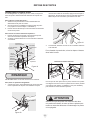
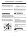
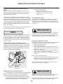
Warranty Registration
It is important you send in your warranty registration card
immediately after taking delivery of your appliance or you
can register online at www.agamarvel.com.
The following information will
be required when registering
your appliance.
Model Number
Serial Number
Date of Purchase
Dealer’s name and address
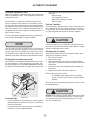
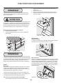
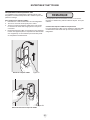
The service number and serial number can be found on the
serial plate which is located inside the right side refrigerator
cabinet on the right side of the cabinet liner. (See gure 1).
Figure 1
Online registration
available at
www.agamarvel.com
UNPACKING YOUR APPLIANCE
x.xx x.xx

4
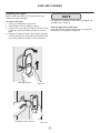
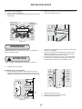
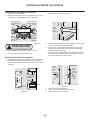
Electrical information
• The refrigerator must be plugged into its own dedicat-
ed 115 Volt, 60 Hz, AC-only non-GFCI electric outlet.
The power cord of the appliance is equipped with a
three-prong grounding plug for your protection against
electrical shock hazards. It must be plugged directly
into a properly grounded three-prong receptacle. The
receptacle must be installed in accordance with local
codes and ordinances. Consult a qualied electrician.
Do not use an extension cord or adapter plug.
• If the power cord is damaged, it should be replaced
by the manufacturer, service technician, or a qualied
person.
• Never unplug the refrigerator by pulling on the power
cord. Always grip the plug rmly and pull straight out
from the receptacle to prevent damaging the power
cord.
• To avoid electrical shock, unplug the refrigerator before
cleaning and before replacing a light bulb or LED light.
• Performance may be affected if the voltage varies by
10% or more. Operating the refrigerator with insufcient
power can damage the compressor. Such damage is
not covered under your warranty.
• Do not plug the unit into an outlet controlled by a wall
switch or pull cord to prevent the refrigerator from being
turned off accidentally.
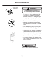
Figure 2
Figure 3
Do not remove
ground prong
!
WARNING
You must follow these guidelines to ensure
that your refrigerator’s safety mechanisms are
operating correctly.
Figure 4
Grounding type
wall receptacle
!
CAUTION
To turn off power to your refrigerator, unplug the
power cord from the wall outlet.
ELECTRICAL INFORMATION

5
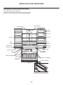
Flipper Guide
LED lights
Covered
door bin
Flipper
mullion
Air lter
ShelvesShelves
Crisper
drawer
Crisper
drawer
Tilt-out
bin
LED lightLED light
Freezer baskets
Water
lter
Ice
maker
Ice
bucket
Toe grille
Wire tilt-out shelf
(inside freezer drawer)
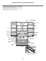
FEATURE OVERVIEW
Understanding features and terms
Your refrigerator is designed for optimal convenience and
storage exibility. The illustration below is provided to assist
you with familiarizing yourself with product features and
terminology.
Model is shown
without freezer
door cover
Select
temperature
drawer
Door
hinges
Figure 5
Specialty items rack,
inside drawer

6
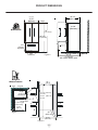
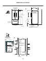
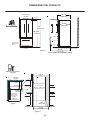
PRODUCT DIMENSIONS
Figure 6
Figure 7
Figure 8
Rough In
Measurements
Electrical
Water
1” (2.5 cm)
air gap
24” (61 cm)
cabinet depth
41-1/4”
(105 cm)
w/ door open 90
4” (10.2 cm)
gap
for door swing
25” (63.5 cm)
counter depth
36-1/2”
(92.7 cm)
4/1-07
(
)mc 4.871
no cowl
76-1/4”
”
(
193.7 cm)
6” cowl
Dimensions
Body Width
35 5/8”
(90.5 cm)
Hinge
3/8”
front leg
adjusters
front
stabilizers
with freezer drawer open
25”
(63.5 cm)
26 7/8”
(68.3 cm)
23 5/8”
(60.0 cm)
44 1/2”
(113.0 cm)
68 3/16”
(173.2 cm)
70”
(177.8 cm)

7
INSTALLATION
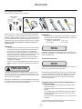
Required tools
You will need the following tools:
Components
provided:
Top hinge
cover
rear screw
Top hinge cover
front screw
Lower
hinge
screw
Top
hinge
screw
Tools necessary:
Phillips™ Head
or #2 square
drive head
(or)
(or)
(or) (or)
And
Socket wrench set
Adjustable
wrench
3/8" Fixed
wrench
1/4" Nut
driver
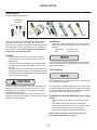
This Use & Care Guide provides general installation and
operating instructions for your model. We recommend
using a service or kitchen contracting professional to install
your refrigerator. Use the refrigerator only as instructed in
this Use & Care Guide. Before starting the refrigerator,
follow these important rst steps.
Location
• Choose a place that is near a grounded, non-GFCI,
electrical outlet. Do Not use an extension cord or an
adapter plug.
• If possible, place the refrigerator out of direct sunlight
and away from the range, dishwasher, or other heat
sources.
• The refrigerator must be installed on a oor that is level
and strong enough to support a fully loaded refrigerator.
• Consider water supply availability for models equipped
with an automatic ice maker.
!
CAUTION
DO NOT install the refrigerator where the temperature will
drop below 55°F (13°C) or rise above 110°F (43°C). The
compressor will not be able to maintain proper tempera-
tures inside the refrigerator.
DO NOT block the toe grille on the lower front of your re-
frigerator. Sufcient air circulation is essential for the proper
operation of your refrigerator.
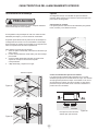
Installation
• Allow the following clearances for ease of installation,
proper air circulation, and plumbing and electrical con-
nections:
Sides & Top ⅜ inch (9.5 mm)
Back 1 inch (25.4 mm)
NOTE
NOTE
If your refrigerator is placed with the door hinge against a
wall, you may have to allow additional space so the door
can be opened wider.
Door opening
The refrigerator doors are designed to shut by themselves
within a 20 degree opening.
Your refrigerator should be positioned to allow easy access
to a counter when removing food. For best use of refrigera-
tor drawers and freezer baskets, the refrigerator should be
in a position where both can be fully opened.
Guidelines for nal positioning of your refrig-
erator
• All four corners of the cabinet must rest rmly on the
oor.
• The cabinet should be level at the front and rear.
• The sides should tilt ¼ inch (6 mm) from front to back
(to ensure that doors close and seal properly).
• Doors should align with each other and be level.
Most of these conditions can be met by raising or
lowering the adjustable front rollers.
Figure 9
Rough In
Measurements
Electrical
Water
1” (2.5 cm)
air gap
24” (61 cm)
cabinet depth
41-1/4”
(105 cm)
w/ door open 90
4” (10.2 cm)
gap
for door swing
25” (63.5 cm)
counter depth
36-1/2”
(92.7 cm)
4/1-07
(
)mc 4.871
no cowl
76-1/4”
”
(
193.7 cm)
6” cowl
Dimensions
Body Width
35 5/8”
(90.5 cm)
Hinge
3/8”
front leg
adjusters
front
stabilizers
with freezer drawer open
25”
(63.5 cm)
26 7/8”
(68.3 cm)
23 5/8”
(60.0 cm)
44 1/2”
(113.0 cm)
68 3/16”
(173.2 cm)
70”
(177.8 cm)

8
INSTALLATION
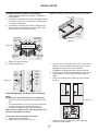
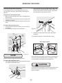
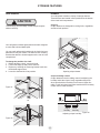
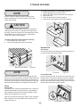
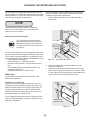
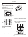
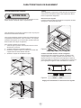
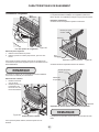
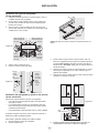
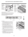
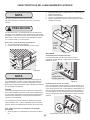
Leveling Freezer Drawer (if necessary)
1. Check gasket seal around top, bottom, and sides of
freezer drawer.
2. If gasket is not sealed, open drawer and slightly loosen
four drawer screws (two on each side) to allow drawer
to rotate (see illustration).
3. Close drawer and recheck the seal on the gasket (A).
Open the drawer grabbing by the sides in the center
(B). Be careful not to rotate the drawer.
Remove hex
head drawer
screw
Remove hex
head drawer
screw
Remove hex
head drawer
screw
Remove hex
head drawer
screw
Do not remove
other screws
4. Tighten four drawer screws.
5. Recheck gasket seal.
Push
against
freezer
drawer
Grab
drawer
at center
from both
sides
then
pull
drawer
out
A
B
Level Refrigerator & Adjust Doors (if neces-
sary)
Guidelines for nal positioning of your refrigerator:
• All four corners of the cabinet must rest rmly on the
oor.
• The sides should tilt ¼ inch (6 mm) from front to back
(to ensure that doors close and seal properly).
• Doors should align with each other and be level.
Most of these conditions can be met by raising or low-
ering the adjustable front rollers.
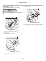
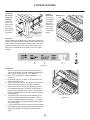
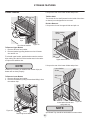
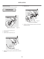
To level the cabinet using the front rollers:
1. Slightly open freezer drawer.
2. Remove the toe grille. See Figure 13.
Figure 13: Remove screws and then gently pull forward.
Remove
mounting
screws
3. You can raise or lower each door. Use a ⅜ inch socket
wrench to turn the adjustment screws (one per side).
To raise: turn adjustment screw clockwise.
To lower: turn adjustment screw counterclockwise.
4. Ensure both doors are bind-free with their seals touch-
ing the cabinet on all four sides and that cabinet is
stable.
5. After unit is leveled, lower anti-tip leg until it contacts
the oor.
6. Install the toe grille by tting into place (replacing
screws on some models).
Door Door
Anti-tip
leg
Raise
Lower
Figure 10
Figure 11
Figure 12
Figure 13

9
INSTALLATION
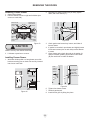
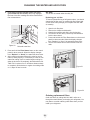
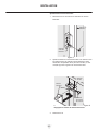
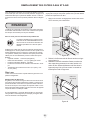
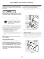
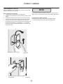
To adjust the door stop:
Door stop is adjustable between 85 to 145 degrees.
NOTE
View shown is looking up at the bottom of the refrigerator
door.
1. Open door to provide access to screw.
2. Loosen screw.
3. Adjust door to desired location.
4. Rotate door stop until it makes contact with the lower
hinge.
5. Re-tighten screw.
6. Ensure door stops in desired location before resuming
normal use.
Lower
hinge
Door
stop
Screw
Adjustable door stop
Adjusting door
Rotate door
to desired
location
Rotate
door
stop
Re-tighten
screw
Re-tighten screw
Figure 14
Figure 15
Figure 16

10
INSTALLATION
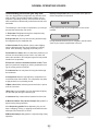
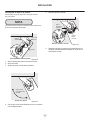
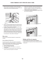
Adjusting ipper mullion screw
Adjusting ipper mullion height
Thickness
of a coin
Flipper
mullion
Flipper
mullion
Mullion
guide
Screw
Flipper
mullion
hinge
To adjust the ipper mullion:
1. Loosen the screw located on the ipper mullion hinge.
2. Adjust ipper mullion height. For proper connection with
the ipper mullion guide, there should be a separation
about the thickness of a coin (0.060 inches, or 1.5 mm)
between the guide and ipper mullion.
3. Re-tighten screw.
Figure 17
Figure 18

11
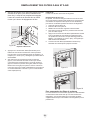
REMOVING THE DOORS
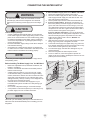
Getting through narrow spaces
If your refrigerator will not t through an entrance area,
you can remove the doors. Check rst by measuring the
entrance.
To prepare for removing the doors:
1. Make sure the electrical power cord is unplugged from
the wall outlet.
2. Open the freezer drawer and remove the toe grille (see
“Installation” section).
3. Remove any food from the door shelves and close the
doors.
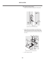
To remove the top hinge covers:
1. Remove the two screws from each cover over the top
door hinges.
2. Lift inside edge of hinge cover and tilt back.
NOTE
DO NOT remove the ground screw from hinge.
To remove the refrigerator doors:
1. Trace lightly around the door’s top hinges with a pencil.
This makes reinstallation easier.
2. Disconnect the harness by grasping both sides of the
connector rmly, depress the latch, and pull apart. Re-
move the two screws from the top hinge. Lift the door
off of the bottom hinge and set it aside.
3. Unscrew the three lower hinge screws and hinge if
necessary.
To reinstall the right door, reverse the above steps.
lower hinge removal
Once both doors are in place, ensure they are aligned with
each other and level (please see the “Installation” section
for more details), and replace the top hinge cover.
!
CAUTION
Be sure doors are set aside in a secure position where they
cannot fall and cause personal injury, or damage to the
doors or handles.
Front
cover screw
Top hinge
cover
Hinge
screws
Rear
cover
screw
Ground
screw
Top
hinge
Multi-wire
cables
Leave
hinge
with
door
Figure 19
Figure 20
Figure 21
Figure 22

12
REMOVING THE DOORS
!
CAUTION
Drawer is heavy. Use caution when lifting.
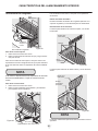
Removing Freezer Drawer
1. Open freezer drawer.
2. Remove drawer screws on right and left sides (two
screws on each side).
3. Lift drawer up and out to remove.
Installing Freezer Drawer
1. With lower slides pulled out, hang drawer onto slide
brackets ensuring pins on each side are fully inserted
into slots on each side.
2. Reinstall four drawer screws (two per side), tighten
down, and close drawer (C).
3. Check gasket seal around top, bottom, and sides of
freezer drawer.
4. If gasket is not sealed, open drawer and slightly loosen
four drawer screws (two on each side) to allow drawer
to rotate.
5. Close drawer and recheck the seal on the gasket (A).
Open the drawer grabbing by the sides in the center
(B). Be careful not to rotate the drawer.
6. Tighten four drawer screws.
7. Recheck gasket seal.
8. Install the toe grille by tting into place.
A
B
Assembly
Pin
Fully extend
drawer slides
Cabinet
Slot
Install
screws
(2) each
side
Push
against
freezer
drawer
Grab drawer
at center
from both
sides, then
pull drawer out
Do not remove
other screws
Remove hex
head drawer
screw
Remove
hex
head drawer
screw
Remove
hex
head drawer
screw
Remove hex
head drawer
screw
Figure 25
Figure 26
Figure 24
Figure 23

13
CONNECTING THE WATER SUPPLY
!
CAUTION
NOTE
NOTE
Check with your local building authority for recommendations on
water lines and associated materials prior to installing your new
refrigerator.
Ensure that your water supply line connections comply with all
local plumbing codes.
To Avoid Property Damage:
• Copper or Stainless Steel braided tubing is recommended
for the water supply line. Water supply tubing made of ¼ inch
plastic is not recommended to be used. Plastic tubing greatly
increases the potential for water leaks, and the manufactur-
er will not be responsible for any damage if plastic tubing is
used for the supply line.
• DO NOT install water supply tubing in areas where tempera-
tures fall below freezing.
• Chemicals from a malfunctioning softener can damage the
ice maker. If the ice maker is connected to soft water, ensure
that the softener is maintained and working properly.
!
WARNING
To avoid electric shock, which can cause death or severe
personal injury, disconnect the refrigerator from electrical
power before connecting a water supply line to the refriger-
ator.
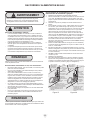
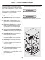
To Connect Water Supply Line To Ice Maker Inlet Valve
1. Disconnect refrigerator from electric power source.
2. Place end of water supply line into sink or bucket. Turn ON
water supply and ush supply line until water is clear. Turn
OFF water supply at shutoff valve.
3. Remove plastic cap from water valve inlet and discard cap.
4. If you use copper tubing - Slide brass compression nut,
then ferrule (sleeve) onto water supply line. Push water sup-
ply line into water valve inlet as far as it will go (¼ inch / 6.4
mm). Slide ferrule (sleeve) into valve inlet and nger tighten
compression nut onto valve. Tighten another half turn with a
wrench; DO NOT over tighten. See Figure 27.
If you use stainless steel tubing - The nut and ferrule are
already assembled on the tubing. Slide compression nut onto
valve inlet and nger tighten compression nut onto valve.
Tighten another half turn with a wrench; DO NOT over
tighten. See Figure 28.
5. With steel clamp and screw, secure water supply line (copper
tubing only) to rear panel of refrigerator as shown.
6. Coil excess water supply line (copper tubing only), about 2½
turns, behind refrigerator as shown and arrange coils so they
do not vibrate or wear against any other surface.
7. Turn ON water supply at shutoff valve and tighten any con-
nections that leak.
8. Reconnect refrigerator to electrical power source.
9. To turn ice maker on, lower wire signal arm (freezer ice
maker) or set the ice maker’s On/Off power switch to the “On”
position (fresh food ice maker).
Before Installing The Water Supply Line, You Will Need:
• Basic Tools: adjustable wrench, at-blade screwdriver, and
Phillips™ screwdriver
• Access to a household cold water line with water pressure
between 30 and 100 psi.
• A water supply line made of ¼ inch (6.4 mm) OD, copper
or stainless steel tubing. To determine the length of tubing
needed, measure the distance from the ice maker inlet valve
at the back of the refrigerator to your cold water pipe. Then
add approximately 7 feet (2.1 meters), so the refrigerator can
be moved out for cleaning (as shown).
• A shutoff valve to connect the water supply line to your
household water system. DO NOT use a self-piercing type
shutoff valve.
• Do not reuse compression tting or use thread seal tape.
• A compression nut and ferrule (sleeve) for connecting a cop-
per water supply line to the ice maker inlet valve.
Plastic water tubing
to ice maker
ll tube
Plastic water tubing
to ice maker
ll tube
Steel
clamp
Steel
clamp
Brass
compression
nut
Ferrule
(sleeve)
Copper
water
line
Water valve
bracket
Water valve
bracket
Valve inlet
Valve inlet
Water valve
Water valve
Copper water line
from household
water supply
Stainless
steel
water line
6 ft. stainless steel water
line from household water
supply
Figure 27 Figure 28

14
NOTE
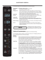
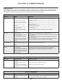
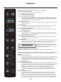
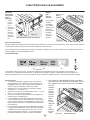
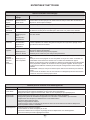
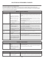
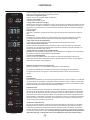
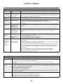
ELECTRONIC CONTROL
A red indicator light will be illuminated above most active features.
Touch the icon to activate the options below.
fast freeze Activates a faster rate for freezing food.
fast ice Increases the production of ice
energy saver Keep this switch set on energy saver (light on) for lowest energy us
age. If moisture appears on the cabinet between the doors, pressing
this button will turn the light off and enable an electric heater used to
reduce moisture on the cabinet between the doors.
water lter Press and hold for three seconds to reset after lter change.
air lter Filter condition status is always displayed when door is open. Press
and hold for three seconds to reset after lter change.
temp mode Touch to toggle display from Fahrenheit to Celsius.
mute sounds Tones emitted by each key press can be turned off based on user
preference. The sounds are muted when the red indicator is lit. Warn-
ing signals will stay active.
default settings Resets all refrigerator settings such as temp, temp display and tones
to their factory default settings.
on off Press and hold for three seconds to turn off the cooling system to
clean the refrigerator. It also turns off the ice maker. The temperature
displays will read OFF.
Pressing the system on/off icon does not
turn off power to your refrigerator. You must
unplug the power cord from the wall outlet.
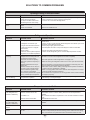
Setting cooling temperatures
Press the + or – indicator to adjust the temperature to the desired setting.
The temperature display will begin to blink with the rst touch. The display will time out
after 10 seconds and return to the basic display.
Alarms
Door Ajar If the door has been left open for an extended period of time, an alarm
will sound and the door ajar indicator will display on the bottom display
of the control panel. The alarm is turned off by closing the door. The
mute sounds key will blink to prompt the reset of any active alarms.
Press this key to reset any system alarms.
High Temp In the event of a high temperature condition, the temperature display
will blink and display “HI”. After 20 minutes, the alarm will sound and
the high temp indicator will be red on the bottom of the control panel.
The mute sounds icon will illuminate until pressed, acknowledging the
alarm, at which time the highest temperature reached will be displayed
and the refrigerator will resume normal operation. In case the high temp
alarm is not acknowledged at the rst alarm sound time out, when the
door is rst opened, the alarm sound will be repeated.
Power fail In the event of a power failure, the power fail alert will be displayed and
the temperature display will blink until the mute sounds icon is pressed,
acknowledging the alarm. Other modes may be turned off until the alarm
is acknowledged. The power fail alert is turned off and the refrigerator
will resume normal operation. The high temp alarm may also be illumi
nated until a safe operating range temperature has been reached.
LED COLORS / Assembly
Figure 29

15
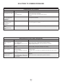
ELECTRONIC CONTROL
Sabbath mode
The Sabbath Mode is a feature that disables portions
of the refrigerator and its controls for, in accordance with
observance of the weekly Sabbath and religious holidays
within the Orthodox Jewish community.
Sabbath Mode is turned ON and OFF by pressing and
holding the freezer temp “-” and the refrigerator temp “+”
indicators for ve seconds. The display shows “Sb” while in
Sabbath mode.
In the Sabbath Mode, the High Temp alarm is active for
health reasons. If a high temperature alarm is activated
during this time, for example due to a door left ajar, the
alarm will sound intermittently for about two minutes. The
alarm will then silence on its own and a red high tempera-
ture icon will display. The high temp icon will continue to
display, even if the door is closed, until the Sabbath mode
is exited and the icon reset. The refrigerator will function
normally once the door is closed, without any violation of
the Sabbath/Holidays.
NOTE
NOTE
NOTE
While in Sabbath Mode, neither the lights nor the control
panel will work until Sabbath Mode is deactivated. Refrig-
erator stays in Sabbath Mode after power failure recovery.
It must be deactivated with the buttons on the control panel.
During Sabbath Mode, the ice maker is turned off by main
control board.
Sabbath Mode and the Select Temp
Drawer
The Select Temp Drawer should be turned off for the
Sabbath/Holidays. Before putting the refrigerator into the
Sabbath mode, turn the Select Temp Drawer off by press-
ing the drawer on/off button. The display will show “OFF”
and the drawer will turn off. Then enter the Sabbath mode
function on the main refrigerator display. See the electronic
control “Sabbath Mode” section. When in Sabbath mode,
the display will not illuminate and the drawer will remain
off. The drawer can still be used as a non-temp controlled
drawer in this mode. When the refrigerator is taken out of
Sabbath mode, the Select Temp Drawer will have to be
turned back on.
If the Select Temp Drawer is not turned off prior to putting
the unit into Sabbath Mode, it will continue to adjust itself to
maintain the set point even if the display does not illuminate
to show that it is still on.

16
AUTOMATIC ICE MAKER
On
Off
Ice maker operation & care
After the refrigerator is installed properly, the ice maker can
produce ice within 24 hours. It can completely ll an ice bin
in about three days.
When using the ice maker for the rst time and in order
for the ice maker to work properly, it is necessary to clear
air from water lter tubing. Once ice maker begins making
ice, allow the bucket to ll completely, then discard the rst
TWO FULL buckets of ice. It will take at least two days to
completely ll the bucket on regular ice making mode or 1½
days on fast ice mode.
The ice maker produces approximately four pounds of ice
every 24 hours depending on usage conditions.
NOTE
Your ice maker is turned on at the factory so it can work as
soon as you install your refrigerator. If you cannot connect
a water supply, lift the ice maker’s wire signal arm to turn it
off. Otherwise, the ice maker’s ll valve may make a loud
chattering noise when it attempts to operate without water.
Turning the ice maker on and off
Ice production is controlled by lifting/lowering the ice mak-
er’s wire signal arm. To gain access to the ice maker, pull
the freezer drawer out. Lift the wire signal arm to turn the
ice maker OFF and lower the wire signal arm to turn it ON.
Wire
signal arm
Ice maker tips
• If your refrigerator is not connected to a water supply or
the water supply is turned off, turn off the ice maker by
lifting wire signal arm.
• Ice cubes stored too long may develop an odd avor.
Empty the ice bin as explained below.
• The following sounds are normal when the ice maker is
operating:
- Motor running
- Ice dropping into ice bin
- Water valve opening or closing
- Running water
Fast Ice Function
Your refrigerator is equipped with a Fast Ice Function, that
will, if activated at your user interface, allow an increase in
ice production. You do not need to deactivate it, if not need-
ed, your refrigerator will operate on normal conditions.
!
CAUTION
If the water supply to your refrigerator is softened, be sure
the softener is properly maintained. Chemicals from a water
softener can damage the ice maker.
Cleaning the ice maker
Clean the ice maker and ice bin at regular intervals, espe-
cially prior to vacation or moving.
1. Turn off the ice maker.
2. Remove the ice bin.
3. Empty and carefully clean the ice bin with mild deter-
gent. Do not use harsh or abrasive cleaners. Rinse with
clean water.
4. Allow the ice bin to dry completely before replacing in
the freezer.
5. Replace the ice bin. Turn the ice maker on.
Remove and empty the ice bin if:
• An extended power failure (one hour or longe)
causes ice cubes in the ice bin to melt and freeze
together.
Remove the ice bin and shake to loosen the cubes or clean
as explained above.
!
CAUTION
NEVER use an ice pick or similar sharp instrument to break
up the ice. This could damage the ice bin. To loosen stuck
ice, use warm water. Before replacing the ice bin, make
sure it is completely dry.
Figure 30

17
!
CAUTION
To avoid injury from breakage, handle tempered glass
shelves carefully.
Your refrigerator includes glass shelves that are designed
to catch and hold accidental spills.
You can easily adjust shelf positions in the fresh food com-
partments to suit your needs. The shelves have mounting
brackets that attach to slotted supports at the rear of each
compartment.
To change the position of a shelf:
1. Before adjusting a shelf, remove all food.
2. Lift the front edge up and pull the shelf out.
3. Replace by inserting the mounting bracket hooks into
the desired support slots.
4. Lower the shelf and lock into position.
Shelf features Drawers
Your refrigerator includes a variety of storage drawers.
These drawers are located in xed positions at the bottom
of the fresh food compartment.
Crispers
Crisper drawers are designed for storing fruits, vegetables,
and other fresh produce.
Crisper humidity control
Crisper drawers include a sliding control for adjusting the
humidity inside the crisper. Leafy vegetables keep best
when stored with the Humidity Control set on Higher Hu-
midity. Fresh fruits keep best when stored with the Humidity
Control set on Lower Humidity.
STORAGE FEATURES
or
Opening crisper drawer
Humidity control
Higher
humidity
Lower
humidity
Adjusting crisper humidity
Figure 31
Figure 33
Figure 34
Figure 32

18
STORAGE FEATURES
Opening the drawer
To operate:
1. To turn on and off, press the drawer’s On/Off button.
The numeric display will show a temperature between
“28°F and 42°F” when on and “OFF” when off.
2. Press F/C if you prefer to display Fahrenheit “F,” or
Celsius “C”.
3. Press either the up or down scroll buttons to illu-
minate the desired item.
4. Once an option is selected, the drawer will adjust and
maintain the temperature for the setting selected.
5. When turned off, the Select Temp Drawer functions
as a standard meat pan. The Select Temp Drawer is
best used for packaged food products. Leafy vegeta-
bles and unpackaged fruits are best kept in one of the
crisper drawers.
6. The three favorite selections provide exibility to set
and store personal temperature selections. The tem-
perature is adjusted up by pressing the + or – buttons.
The drawer will store the selected temperature setting
until it is changed.
7. 7 The control buttons can be locked to prevent acciden-
tal changes by pressing the control lock button for three
seconds. Deactivate by pressing for three seconds
again.
<
<
To remove
the crisper
drawer for
cleaning:
1. Pull the
drawer out
until it stops.
2. Lift the
front slightly
and remove
the drawer.
Special
items rack
The innova-
tive design of
the special
items rack
allows you to
store 4 bot-
tles of wine
or soft drink
bottles.
Cool zone
Some models are equipped with a meat keeper drawer for
short-term storage of bulk meat items. This drawer includes
sliding controls for adjusting the humidity inside. Any meat
to be kept longer than two days should be frozen. If you
store fruits or vegetables in this drawer, set it to a higher
humidity.
Removing crisper
drawer
Special items
rack
Figure 35
Figure 36
Figure 37
Figure 38

19
Adjustable Door Bin
NOTE
!
CAUTION
NOTE
STORAGE FEATURES
DO NOT clean the display area of the Select Temp
Drawer with abrasive or caustic cleaners. Wipe clean
with a moist sponge.
The Select Temp Drawer and cover can be removed for
cleaning but the control unit, attached to the right side of
the fridge, cannot be removed. Do not immerse the Select
Temp Drawer cover in water or put it in a dishwasher.
Clean with a damp cloth or sponge.
To remove the Select Temp Drawer for cleaning:
1. Pull the drawer out until it stops.
2. Lift the front slightly and remove the drawer.
Removing the drawer
When the refrigerator is turned off by pressing the main
electronic control on/off button, the Select Temp Drawer will
also be turned off. When the refrigerator is turned back on,
the Select Temp Drawer will resume operations at the temp
setting that was set before the refrigerator was turned off.
Doors
Storage bins
The doors to your fresh food compartment use a system of
modular storage bins. All of these bins are removable for
easy cleaning. Some of them have xed positions, while
others can be adjusted to your needs.
Door bins are ideal for storing jars, bottles, cans, and large
drink containers. They also enable quick selection of fre-
quently used items.
Covered door bin
Lock
Tilt can bin
Covered Door Bin
Use the covered door bin, at the top of the fresh food com-
partment door, for short-term storage of cheese, spreads,
or butter. The covered door bin is designed to be warmer
than the open area and includes a lift-up cover that may be
locked and a dairy divider (select models).
Accesorries
Tilt can bins
The can bins allow you to efciently and securely store up
to eight 12-ounce canned beverages.
To change the position of an adjustable door bin:
1. Before adjusting a bin, remove all food.
2. Grip the bin rmly with both hands and lift it upward.
3. Remove the bin.
4. Place the bin just above desired position.
5. Lower the bin onto supports until locked in place.
Figure 39
Figure 40
Figure 41
Figure 42

20
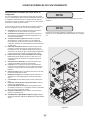
STORAGE FEATURES
Freezer Features
Stabilizer bar
Basket
retainer
clips
To Remove Upper Basket
1. Remove all items from basket.
2. Remove basket by pulling basket out to its full exten-
sion and lift out.
To reinstall upper basket, position basket onto the retainer
clips making sure the front of the basket rests in the retain-
er clips on the stabilizer bar.
Two freezer baskets
NOTE
NOTE
If basket is not resting on stabilizer bar retainer clips, the
drawer will not close properly.
Removing lower basket
Basket
retainer
To Remove Lower Basket
1. Remove all items from basket.
2. Remove the basket by tilting it forward and lifting it from
the retainer clips.
Spill Guard Tray should be hand washed in warm water.
Lower basket divider and
spill guard tray
Lower basket
divider
Spill guard
tray
Lift up on the rear of the lower divider and pull out.
Upper basket divider
Middle basket
divider
Retainers
Stabilizer
bar
Lift up on the rear of the lower divider and pull out.
Tilt Wire Shelf
The freezer tilt wire shelf (located on the inside of the freez-
er drawer) is not designed to be removed.
Dividers Removal
Lift up on the front of the upper divider and pull out.
Figure 43
Figure 44
Figure 46
Figure 45
La page est en cours de chargement...
La page est en cours de chargement...
La page est en cours de chargement...
La page est en cours de chargement...
La page est en cours de chargement...
La page est en cours de chargement...
La page est en cours de chargement...
La page est en cours de chargement...
La page est en cours de chargement...
La page est en cours de chargement...
La page est en cours de chargement...
La page est en cours de chargement...
La page est en cours de chargement...
La page est en cours de chargement...
La page est en cours de chargement...
La page est en cours de chargement...
La page est en cours de chargement...
La page est en cours de chargement...
La page est en cours de chargement...
La page est en cours de chargement...
La page est en cours de chargement...
La page est en cours de chargement...
La page est en cours de chargement...
La page est en cours de chargement...
La page est en cours de chargement...
La page est en cours de chargement...
La page est en cours de chargement...
La page est en cours de chargement...
La page est en cours de chargement...
La page est en cours de chargement...
La page est en cours de chargement...
La page est en cours de chargement...
La page est en cours de chargement...
La page est en cours de chargement...
La page est en cours de chargement...
La page est en cours de chargement...
La page est en cours de chargement...
La page est en cours de chargement...
La page est en cours de chargement...
La page est en cours de chargement...
La page est en cours de chargement...
La page est en cours de chargement...
La page est en cours de chargement...
La page est en cours de chargement...
La page est en cours de chargement...
La page est en cours de chargement...
La page est en cours de chargement...
La page est en cours de chargement...
La page est en cours de chargement...
La page est en cours de chargement...
La page est en cours de chargement...
La page est en cours de chargement...
La page est en cours de chargement...
La page est en cours de chargement...
La page est en cours de chargement...
La page est en cours de chargement...
La page est en cours de chargement...
La page est en cours de chargement...
La page est en cours de chargement...
La page est en cours de chargement...
La page est en cours de chargement...
La page est en cours de chargement...
La page est en cours de chargement...
La page est en cours de chargement...
La page est en cours de chargement...
La page est en cours de chargement...
La page est en cours de chargement...
La page est en cours de chargement...
La page est en cours de chargement...
La page est en cours de chargement...
La page est en cours de chargement...
La page est en cours de chargement...
La page est en cours de chargement...
La page est en cours de chargement...
La page est en cours de chargement...
La page est en cours de chargement...
-
 1
1
-
 2
2
-
 3
3
-
 4
4
-
 5
5
-
 6
6
-
 7
7
-
 8
8
-
 9
9
-
 10
10
-
 11
11
-
 12
12
-
 13
13
-
 14
14
-
 15
15
-
 16
16
-
 17
17
-
 18
18
-
 19
19
-
 20
20
-
 21
21
-
 22
22
-
 23
23
-
 24
24
-
 25
25
-
 26
26
-
 27
27
-
 28
28
-
 29
29
-
 30
30
-
 31
31
-
 32
32
-
 33
33
-
 34
34
-
 35
35
-
 36
36
-
 37
37
-
 38
38
-
 39
39
-
 40
40
-
 41
41
-
 42
42
-
 43
43
-
 44
44
-
 45
45
-
 46
46
-
 47
47
-
 48
48
-
 49
49
-
 50
50
-
 51
51
-
 52
52
-
 53
53
-
 54
54
-
 55
55
-
 56
56
-
 57
57
-
 58
58
-
 59
59
-
 60
60
-
 61
61
-
 62
62
-
 63
63
-
 64
64
-
 65
65
-
 66
66
-
 67
67
-
 68
68
-
 69
69
-
 70
70
-
 71
71
-
 72
72
-
 73
73
-
 74
74
-
 75
75
-
 76
76
-
 77
77
-
 78
78
-
 79
79
-
 80
80
-
 81
81
-
 82
82
-
 83
83
-
 84
84
-
 85
85
-
 86
86
-
 87
87
-
 88
88
-
 89
89
-
 90
90
-
 91
91
-
 92
92
-
 93
93
-
 94
94
-
 95
95
-
 96
96


dans d''autres langues
- English: AGA AMPROFD23SS User guide
- español: AGA AMPROFD23SS Guía del usuario
Documents connexes
Autres documents
-
Heartland HCFDR23BLK HCFDR23 owners guide
-
Marvel AMPROFD23-SS Mode d'emploi
-
Viking RVRF3361 Use/Install Manual
-
Viking RVRF3361SS Mode d'emploi
-
Frigidaire Professional FPSC2277RF Guide d'installation
-
Crosley GRSC2352AF Guide d'installation
-
-
-
Electrolux 242090103 Mode d'emploi
-
Equator-Ascoli IM116000 Le manuel du propriétaire