Cooper GHG 635 Operating Instructions Manual
- Taper
- Operating Instructions Manual

Betriebsanleitung
Explosionsgeschützte Motorschutzschalter bis
25A, GHG 635
Operating instructions
Explosion-protected manual motor starters up
to 25A, GHG 635
Mode d’emploi
Disjoncteurs moteur jusqu'à 25A, GHG 635,
pour atmosphères explosibles
GHG 630 7011 P0003 D/E/F (E)

Cooper Crouse-Hinds GmbH
22
22
2
Explosionsgeschützter
Motorschutzschalter bis 25A,
GHG 635
Inhalt:
Inhalt ........................................ 2
Maßbild.................................... 3
1 Technische Angaben .............. 3
1.1 Motorschutzschalter ............... 3
1.2 Hilfskontakt .............................. 3
1.3 Unterspannungsauslöser ....... 3
1.4 Größter Bemessungsstrom
der Kurzschlussvorsicherung
bei max. 50 kA ........................ 4
1.5 Größter Bemessungsstrom
der Kurzschlussvorsicherung
bei max. 100 kA ...................... 4
1.6 Temperaturklasse und
Verdrahtungsquerschnitt ........ 4
1.7 Auslösestrom und
Auslösezeit .............................. 5
2 Sicherheitshinweise ................ 5
3 Normenkonformität ................. 5
4 Verwendungsbereich .............. 5
5 Verwendung/
Eigenschaften .......................... 5
6 Installation ................................ 6
6.1 Montage .................................. 6
6.2 Öffnen des Gerätes/
Elektrischer Anschluss ........... 6
6.3 Kabel- und Leitungs-
einführung; Verschluss-
stopfen..................................... 6-7
6.4 Flansche und Metallplatten .... 7
6.5 Schließen des Gerätes ........... 7
6.6 Inbetriebnahme ....................... 7
7 Instandhaltung/Wartung ......... 7
8 Reparatur / Instandsetzung
Änderungen ............................. 7
9 Entsorgung / Wieder-
verwertung .............................. 7
10 Konformitätserklärung ............. 18
Contents:
Contents .................................. 2
Dimensional drawings ............. 8
1 Technical data ......................... 8
1.1 Manual motor starters ............ 8
1.2 Auxiliary contact ...................... 8
1.3 Undervoltage trip .................... 8
1.4 Max. rating current of
short-circuit back-up fuse
for max. 50 kA ......................... 9
1.5 Max. rating current of
short-circuit back-up fuse
for max. 100 kA ....................... 9
1.6 Temperature class and
conductor cross section......... 9
1.7 Tripping current and time........ 10
2 Safety instructions .................. 10
3 Conformity with standards ..... 10
4 Field of application .................. 10
5 Application/Properties ............ 10
6 Installation ................................ 11
6.1 Mounting .................................. 11
6.2 Opening apparatus /
Electrical connection ............... 11
6.3 Cable entry (KLE);
blanking plug ........................... 11-12
6.4 Flanges and metal plates ........ 12
6.5 Closing apparatus .................. 12
6.6 Putting into operation .............. 12
7 Maintenance/Servicing ........... 12
8 Repairs/Modifications ............ 12
9 Disposal/Recycling ................. 12
10 Declaration of conformity ........ 18
Contenu:
Contenu ................................... 2
Plans cotés .............................. 13
1 Caractéristiques
techniques ............................... 13
1.1 Disjoncteurs moteur ................ 13
1.2 Contact auxiliaire ..................... 13
1.3 Déclencheur sur baisse
de tension ................................ 13
1.4 Courant max. de court-circuit
du fusible pour max. 50 kA .... 14
1.5 Courant max. de court-circuit
du fusible pour max. 100 kA .. 14
1.6 Classe de température et
diamètre des conducteurs ..... 14
1.7 Courant et temps de
déclenchement........................ 15
2 Consignes de sécurité ............ 15
3 Conformité avec les
normes..................................... 15
4 Domaine d’utilisation ............... 15
5 Utilisation/Propriétés ............... 15
6 Installation ................................ 16
6.1 Montage .................................. 16
6.2 Ouverture de l’appareil/
Raccordement électrique ....... 16
6.3 Entrées de câble (KLE)
bouchons de fermeture .......... 16-17
6.4 Plaques à brides..................... 17
6.5 Fermeture de l’appareil/
Fermeture du couvercle ......... 17
6.6 Mise en service ....................... 17
7 Maintien/Entretien ................... 17
8 Réparation/Remise
en état/Modifications .............. 17
9 Évacuation des déchets/
Recyclage ............................... 17
10 Déclaration de conformité ....... 18
Explosion-protected manual
motor starters up to 25 A,
GHG 635
Disjoncteurs moteur jusqu'à
25A, GHG 635 pour
atmosphères explosibles

Cooper Crouse-Hinds GmbH
33
33
3
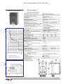
1 Technische Angaben
1.1 Motorschutzschalter GHG 635
Gerätekennzeichnung nach 94/9/EG: II 2 G Ex e d II C T6 / T5*
II 2 D Ex tD A21 IP66 80° C
* Temperaturklasse siehe Punkt 1.6, Seite 4
EG-Baumusterprüfbescheinigung: PTB 99 ATEX 1162
Nennspannung: 690 V, 50/60 Hz / 440V DC
Nennstrom: bis 25A
Kurzschlussvorsicherung: siehe Punkt 1.4 und 1.5, Seite 4
Schaltvermögen AC 3: 690 V / 25 A
Thermische Auslösecharakteristik: T II
Auslösezeit: Siehe Diagramm 1, S.3, sowie Punkt 1.7 S.5
Zulässige Umgebungstemperatur: -20° C bis +40° C (Listenausführung)
Abweichende Temperaturen sind bei Sonderversionen möglich
Zul. Lagertemperatur in Originalverpackung: -40° C bis +80° C
Schutzart nach EN/IEC 60529 : IP 66 (Listenausführung)
Schutzklasse nach EN/IEC 61140: I - wird von den Geräten erfüllt
II - mit Metallflansch
Leitungseinführung: (Listenausführung)
0,1A - 6,3A 2 x M25 für Leitungen von Ø 8 - 17mm
6,3A - 25,0A 2 x M32 für Leitungen von Ø 12 - 21mm
mit Hilfskontakt / Unterspannungsauslöser zusätzlich 1 x M25
Anschlussklemme: 2 x 0,75 - 4, 0mm² oder 1 x 10mm²
Prüfdrehmomente:
Druckschraube der KLE M20 M25 M32 M40
für min. Kabel Ø in Nm 3,50 5,00 8,00 11,0
für max. Kabel Ø in Nm 2,50 3,50 5,00 5,00
Deckelschrauben 2,5 Nm
Anschlussklemmen (Hauptkontakte) 3,5 Nm
Anschlussklemmen (Hilfskontakte)) 2,5 Nm
Anschlussklemmen (Unterspannungsauslöser) 2,5 Nm
Gewicht:
Standardausführung ca. 2,45 kg
mit Hilfskontakt / Unterspannungsauslöser ca. 2,55 kg
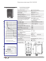
Motorschutzschalter bis 25A, GHG 635
Maßangaben in mm
X = Befestigungsmaße
1.2 Hilfskontakt
Nennspannung: bis 400V AC
Nennstrom: bis 2A
Schaltvermögen AC 15: 230V / 2 A 400V / 0,5 A
Schaltvermögen DC 13: 60V / 2 A 230V / 0,25 A
Zulässige Kurzschlussvorsicherung: max. 10 A gL
Anschlussklemmen: 2 x 0,75 - 2,5 mm²
1.3 Unterspannungsauslöser
Nennspannungen: 110 V, 230 V, 400 V, 500 V 50/60 Hz
Abfallwert: 35....75 % von U
c
Anzugswert: >85 % von U
c
Kurzschlussvorsicherung: nicht erforderlich
Anschlussklemmen: 2 x 0,75 - 2,5 mm²
Motorschutzschalter GHG 635
Diagramm 1
Auslösezeit
Vielfaches des Einstellstromes
Anschlussbild
1 = thermische Auslösung
2 = elektromagnetische Auslösung

Cooper Crouse-Hinds GmbH
44
44
4
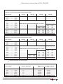
Motorschutzschalter bis 25A, GHG 635
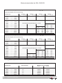
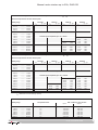
1.4 Größter Bemessungsstrom der Kurzschlussvorsicherung bei max. 50 kA, wenn I
cc
> I
cs
*
Kurzschlussfestigkeit und max. Vorsicherung
Einstellbereich 240 V AC 400V AC 500V AC 690V AC
I
cs
gL, aM I
cs
gL, aM I
cs
gL, aM I
cs
gL, aM
0,10 A ......... 0,16 A
0,16 A ......... 0,25 A
0,25 A ......... 0,40 A
0,40 A ......... 0,63 A Kurzschlussfest
0,63 A ......... 1,00 A
1,00 A ......... 1,60 A keine Vorsicherung notwendig bis I
cc
= 50 kA
1,60 A ......... 2,50 A 40 kA 25A
2,50 A ......... 4,00 A 10 kA 40A
4,00 A ......... 6,30 A 40 kA 50A 7 kA 40A
6,30 A ......... 9,00 A 30 kA 80A 5 kA 50A
9,00 A ......... 12,50 A 27 kA 80A 4,5 kA 50A
12,50 A ......... 16,00 A 25 kA 100A 4 kA 50A
16,00 A ......... 20,00 A 22 kA 100A 3,5 kA 50A
20,00 A ......... 25,00 A 20 kA 125A 3 kA 50A
1.5 Größter Bemessungsstrom der Kurzschlussvorsicherung bei max. 100 kA, wenn I
cc
> I
cs
*
Kurzschlussfestigkeit und max. Vorsicherung
Einstellbereich 240 V AC 400V AC 500V AC 690V AC
I
cs
gL, aM I
cs
gL, aM I
cs
gL, aM I
cs
gL, aM
0,10 A ......... 0,16 A
0,16 A ......... 0,25 A
0,25 A ......... 0,40 A
0,40 A ......... 0,63 A Kurzschlussfest
0,63 A ......... 1,00 A
1,00 A ......... 1,60 A keine Vorsicherung notwendig bis I
cc
= 100 kA
1,60 A ......... 2,50 A 40 kA 25A
2,50 A ......... 4,00 A 60 kA 35 / 40A 10 kA 40A
4,00 A ......... 6,30 A 40 kA 50A 7 kA 40A
6,30 A ......... 9,00 A 30 kA 80A 5 kA 50A
9,00 A ......... 12,50 A 75 kA 80A 27 kA 80A 4,5 kA 50A
12,50 A ......... 16,00 A 60 kA 100A 25 kA 100A 4 kA 50A
16,00 A ......... 20,00 A 55 kA 100A 22 kA 100A 3,5 kA 50A
20,00 A ......... 25,00 A 50 kA 125A 20 kA 125A 3 kA 50A
1.6 Temperaturklasse und Verdrahtungsquerschnitt
Einstellbereich Temperaturklasse Mindestanschlussquerschnitt
Zugang Abgang
0,10 A ......... 1,60 A T 6 0,75 mm² 0,75 mm²
1,60 A ......... 2,50 A T 6 1,00 mm² 1,00 mm²
2,50 A ......... 4,00 A T 6 1,00 mm² 1,50 mm²
4,00 A ......... 9,00 A T 6 1,50 mm² 1,50 mm²
9,00 A ......... 12,50 A T 6 2,50 mm² 2,50 mm²
12,50 A ......... 20,00 A T 5 2,50 mm² 2,50 mm²
20,00 A ......... 25,00 A T 5 4,00 mm² 4,00 mm²
* I
cc
= prospectiver Kurzschlussstrom am Einbauort
I
cs
= Bemessungsbetriebskurzschlussausschaltvermögen

Cooper Crouse-Hinds GmbH
55
55
5
2 Sicherheitshinweise
Die Motorschutzschalter sind
nicht für Zone 0 und 20
geeignet. Die auf den Geräten
angegebene Temperaturklasse
und Zündschutzart ist zu beachten.
Die Anforderungen der EN 61241-0 und -1
u.a. in Bezug auf übermäßige Staubab-
lagerungen und Temperatur, sind vom
Anwender zu beachten.
Umbauten oder Veränderungen an den
Motorschutzschaltern sind nicht gestattet.
Sie sind bestimmungsgemäß in unbeschä-
digtem und einwandfreiem Zustand zu be-
treiben.
Als Ersatz und zur Reparatur dürfen nur
Originalteile von COOPER Crouse-Hinds ver-
wendet werden.
Reparaturen, die den Explosionsschutz
betreffen, dürfen nur von COOPER Crouse-
Hinds oder einer qualifizierten Elektro-
fachkraft in Übereinstimmung mit national
geltenden Regeln durchgeführt werden.
Vor Inbetriebnahme müssen die Motor-
schutzschalter entsprechend der im Ab-
schnitt 6 genannten Anweisung geprüft
werden.
4 Verwendungsbereich
Die Motorschutzschalter sind zum Einsatz in
explosionsgefährdeten Bereichen der Zonen 1
und 2 sowie der Zonen 21 und 22 gemäß
IEC 60079-10 geeignet!
Motorschutzschalter bis 25A, GHG 635
5 Verwendung/Eigenschaften
Die Motorschutzschalter dienen zum Schutz
von explosionsgeschützten Motoren in jeder
Zündschutzart vor Überlast und Phasenaus-
fall. Temperaturklasse, Explosionsgruppe,
Auslösecharakteristik, und zulässige
Umgebungstemperatur sowie das Auslöse-
diagramm sind aus den technischen Daten zu
entnehmen.
Durch das AC 3 Motorschaltvermögen der
Motorschutzschalter ist eine sichere Trennung
(Schalten) auch während des Betriebes
möglich.
Die Verwendung eines Unterspannungs-
auslösers verhindert das selbstständige
Anlaufen des Motores. Darüber hinaus kann
der Unterspannungsauslöser zur Abschaltung
im Not-Aus-Stromkreis verwendet werden.
Der Hilfskontakt (optional) dient hauptsächlich
zur Signalgebung des Motorschutzschalter-
betriebszustandes.
Der Motorschutzschalter kann in AUS-Stellung
mit 3 Vorhängeschlösser gegen unbefugtes
Schalten gesichert werden (Bügeldurchmesser
der Vorhängeschlösser von 4-6mm, siehe Bild 1).
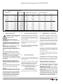
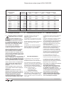
1.7 Auslösestrom und Auslösezeit
Einstellbereich Auslösestrom Auslösezeit in Sekunden bei .. - fachen des Einstellstromes
3-fach 4-fach 5-fach 6-fach 8-fach
0,10 A ......... 0,16 A 1,92 A 15,0 s 9,0 s 6,5 s 4,8 s 3,2 s
0,16 A ......... 0,25 A 3,00 A 16,0 s 10,0 s 6,8 s 5,2 s 3,6 s
0,25 A ......... 0,40 A 4,80 A 16,0 s 9,7 s 6,5 s 5,0 s 3,3 s
0,40 A ......... 0,63 A 7,56 A 17,0 s 10,2 s 7,3 s 5,7 s 3,9 s
0,63 A ......... 1,00 A 14,00 A 17,5 s 10,2 s 7,2 s 5,5 s 3,8 s
1,00 A ......... 1,60 A 22,40 A 17,0 s 10,0 s 7,1 s 5,6 s 4,0 s
1,60 A ......... 2,50 A 35,00 A 18,0 s 10,3 s 7,5 s 5,9 s 4,2 s
2,50 A ......... 4,00 A 60,00 A 18,4 s 11,5 s 8,1 s 6,4 s 4,6 s
4,00 A ......... 6,30 A 94,50 A 19,0 s 12,0 s 8,5 s 6,7 s 4,9 s
6,30 A ......... 9,00 A 135,00 A 18,2 s 11,5 s 7,9 s 6,0 s 3,8 s
9,00 A ......... 12,50 A 187,50 A 19,0 s 11,5 s 8,0 s 6,0 s 4,0 s
12,50 A ......... 16,00 A 240,00 A 19,5 s 11,5 s 7,5 s 5,4 s 3,3 s
16,00 A ......... 20,00 A 300,00 A 20,0 11,5 s 7,8 s 5,7 s 3,5 s
20,00 A ......... 25,00 A 375,00 A 20,0 s 10,4 s 7,0 s 5,0 s 3,2 s
3 Normenkonformität
Das Betriebsmittel ist gemäß DIN EN ISO 9001
entwickelt, gefertigt und geprüft worden.
Es entspricht den in der Konformitätser-
klärung aufgeführten Normen.
94/9 EG: Geräte und Schutzsysteme zur
bestimmungsgemäßen Verwendung in
explosionsgefährdeten Bereichen.
Weitere Anforderungen wie die EG Richtlinie
Elektromagnetische Verträglichkeit
(2004/108/EG) werden von den Steuergerä-
ten erfüllt.
Die eingesetzten Gehäusematerialien ein-
schließlich der außenliegenden Metallteile
bestehen aus hochwertigen Werkstoffen, die
einen anwendungsgerechten Korrosionsschutz
und Chemikalienresistenz in "normaler
Industrieatmosphäre" gewährleisten:
- schlagfestes Polyamid
- glasfaserverstärktes Polyester
- Edelstahl AISI 316 L.
Bei einem Einsatz in extrem aggressiver
Atmosphäre, können Sie zusätzliche Informa-
tionen über die Chemikalienbeständigkeit der
eingesetzten Kunststoffe, bei Ihrer zuständi-
gen Cooper Crouse-Hinds Niederlassung
erfragen.
Alle Fremdkörper müssen vor der ersten
Inbetriebnahme aus den Geräten entfernt
werden.
Achtung:
Anschlussquerschnitte des Motorschutz-
schalters in Tabelle 1.6, Seite 4 beachten.
Beachten Sie die nationalen Sicherheits-
und Unfallverhütungsvorschriften und die
nachfolgenden Sicherheitshinweise in
dieser Betriebsanleitung, die wie dieser
Text in Kursivschrift gefasst sind!
Bild 1

Cooper Crouse-Hinds GmbH
66
66
6
6.2 Öffnen des Gerätes /
Elektrischer Anschluss
Vor Öffnen der Geräte ist die Spannungs-
freiheit sicherzustellen bzw. sind geignete
Schutzmaßnahmen zu ergreifen.
Motorschutzschalter bis 25A, GHG 635
6.1 Montage
Die Montage der Motorschutzschalter kann
ohne Öffnen des Gehäuses erfolgen.
Die Schalter dürfen bei der Direktmontage an
der Wand nur an den vorgesehenen
Befestigungspunkten eben aufliegen.
Die gewählte Schraube muss der Befestigungs-
öffnung angepasst sein (siehe Maßbild) und
sie darf die Öffnung nicht beschädigen (z.B.
Verwendung einer Unterlegscheibe).
Das Gerät ist mit mindestens 2 Schrauben
diagonal zu befestigen.
Bei übermäßigem Anziehen der
Befestigungsschrauben, kann das Gerät
beschädigt werden.
Die Motorschutzschalter sind zur Steck-
befestigung auf dem COOPER Crouse-Hinds
- Gerätehalter Grösse 3 durch Einschieben in
die Führungsnut von oben des Gerätehalters
geeignet.
Die betreffende Montageanleitung ist zu
beachten.
6 Installation
Für das Errichten / Betreiben sind die
relevanten nationalen Vorschriften (z.B.
Betri.Si.V., Gerätesicherheitsgesetz in
Deutschland) sowie die allgemein anerkann-
ten Regeln der Technik maßgebend.
Unsachgemäße Installation und Betrieb der
Motorschutzschalter kann zum Verlust der
Garantie führen.
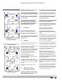
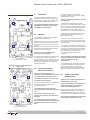
Gerätehalter für Wand- und Gitterrinnen-
befestigung Größe 3
A = Steckbefestigungspunkte
für Motorschutzschalter
A A
A A
A A
A A
Gerätehalter für Rohrbefestigung Größe 3
A = Steckbefestigungspunkte
für Motorschutzschalter
Der elektrische Anschluss des Betriebsmit-
tels darf nur durch Fachpersonal erfolgen.
Die ordnungsgemäß abisolierten Anschluss-
leitungen der Kabel sind unter Berücksichti-
gung einschlägiger Vorschriften anzuschließen.
Zur Aufrechterhaltung der Zündschutzart
ist der Leiteranschluss mit besonderer
Sorgfalt durchzuführen.
Die Isolation der Anschlussleitungen muss
bis an die Klemme heranreichen. Der Leiter
selbst darf nicht beschädigt sein.
Die minimal und maximal anschließbaren
Leiterquerschnitte sind zu beachten (siehe
Punkt 1.6, technische Daten).
Alle Schrauben und/oder Muttern der
Anschlussklemmen, auch die der nicht
benutzten, sind fest anzuziehen.
Bei übermäßigem Anziehen kann der
Anschluss beeinträchtigt oder beschädigt
werden.
Die Anschlussklemmen sind für den Anschluss
von Kupferleitern ausgelegt. Bei der Verwen-
dung von mehr- oder feindrähtigen Anschluss-
kabel /-leitungen sind die Aderenden entspre-
chend den geltenden nationalen und interna-
tionalen Vorschriften zu behandeln (z.B.
Verwendung von Aderendhülsen).
Die Lage der Anschlussklemmen entnehmen
Sie dem Anschlussbild des Schalteinsatzes
und der Darstellung Seite 3 technische Daten.
Um ein korrektes Schließen des Motorschutz-
schalters zu gewährleisten, ist ein Schalten an
der Schaltachse des Schalteinsatzes bei
geöffnetem Gerät nicht zulässig.
Wird der Schalteinsatz, zum leichteren
Einführen der Anschlussleitungen in das
Gehäuse, an den Schnappriegeln (oben oder
unten am Einsatz) aus der Profilschiene am
Gehäuseboden ausgeschnappt, muss vor
dem elektrischen Anschluss der Schalteinsatz
wieder ordnungsgemäß in das Gehäuseunter-
teil eingeschnappt werden.
Der Endhalter auf der Profilschiene dient
zur Fixierung des Schalteinsatzes auf der
Schiene und darf auf keinen Fall demontiert
werden.
Der Anschluss des Unterspannungsauslösers
ist generell auf separate Klemmen geführt
(siehe Anschlussplan Seite 3, technische
Daten). Die dafür vom Einsatzfall abhängige
Verdrahtung des Unterspannungsauslösers ist
vom Anwender durchzuführen.
Angaben aus Punkt 3 und 4 sind bei der
Verwendung zu berücksichtigen.
Andere als die beschriebenen Anwendun-
gen sind ohne schriftliche Erklärung der
Fa. COOPER Crouse-Hinds nicht zulässig.
Beim Betrieb sind die in der Betriebsanlei-
tung unter Punkt 7 genannten Anweisun-
gen zu beachten.
Die Verantwortung hinsichtlich bestim-
mungsgemäßer Verwendung dieser
Motorschutzschalter unter Bezugnahme
der in dieser Anleitung vorhandenen
Rahmenbedingungen (siehe technische
Daten) liegt allein beim Betreiber.

Cooper Crouse-Hinds GmbH
77
77
7
9 Entsorgung / Wiederver-
wertung
Bei der Entsorgung des Betriebsmittels sind die
jeweils geltenden nationalen Abfallbeseitigungs-
vorschriften zu beachten.
Zur Erleichterung der Wiederverwertbarkeit von
Einzelteilen sind Kunststoffteile mit dem Kennzei-
chen des verwendeten Kunststoffes versehen.
Programmänderungen und -ergänzungen sind
vorbehalten.
8 Reparatur / Instand-
setzung / Änderungen
Instandsetzungsarbeiten / Reparaturen dürfen
nur mit COOPER Crouse-Hinds Originaler-
satzteilen vorgenommen werden.
Bei Schäden an der druckfesten Kapselung
ist nur ein Austausch zulässig. Im Zweifels-
falle ist das betroffene Betriebsmittel an
COOPER Crouse-Hinds zur Reparatur
zurückzugeben.
Reparaturen, die den Explosionsschutz
betreffen, dürfen nur von COOPER
Crouse-Hinds oder einer qualifizierten
Elektrofachkraft in Übereinstimmung mit
national geltenden Regeln durchgeführt
werden (EN 60079-17, EN 60079-19).
Umbauten oder Änderungen am Betriebsmittel
sind nicht gestattet; ausgenommen ist das
Anbringen von zusätzlichen KLE's im Rahmen
der Zulassung des Betriebsmittels.
7 Instandhaltung / Wartung
Die für die Wartung / Instandhaltung von
elektrischen Betriebsmitteln in explosions-
gefährdeten Bereichen geltenden nationa-
len Bestimmungen sind einzuhalten
(EN 600079-17).
Vor Öffnen des Gehäuses Spannungs-
freiheit sicherstellen oder geeignete
Schutzmaßnahmen ergreifen.
Die erforderlichen Wartungsintervalle sind
anwendungsspezifisch und daher in Abhängigkeit
von den Einsatzbedingungen vom Betreiber
festzulegen.
Im Rahmen der Wartung sind vor allem die Teile,
von denen die Zündschutzart abhängt, zu prüfen
(z.B. Unversehrtheit der druckfesten Komponen-
ten, des Gehäuses, der Dichtungen und der
Kabel- und Leitungseinführung) sowie die
Rückstellfunktion des Schaltgriffes.
Sollte bei einer Wartung festgestellt werden, dass
Instandsetzungsarbeiten erforderlich sind, ist
Abschnitt 8 dieser Betriebsanleitung zu beachten.
6.6 Inbetriebnahme
Vor Inbetriebnahme des Betriebsmittels sind die in
den einzelnen nationalen Bestimmungen
genannten Prüfungen durchzuführen.
Ausserdem ist vor der Inbetriebnahme die
korrekte Funktion und Installation des Betriebsmit-
tels in Übereinstimmung mit dieser Betriebsanlei-
tung und anderen anwendbaren Bestimmungen
zu überprüfen.
Unsachgemäßer Betrieb der Motorschutz-
schalter kann zum Verlust der Garantie
führen.
6.5 Schließen des Gerätes
Alle Fremdkörper sind aus dem Gerät zu
entfernen.
Die Einstellschraube zur Nennstromeinstellung
am Schalteinsatz ist auf den Motornennstrom
einzustellen.
Der Schaltgriff am Deckel des Motorschutz-
schalters, muss in der gleichen Stellung stehen,
die er beim Öffnen des Gerätes innehatte.
Beim Aufsetzen des Gehäusedeckels ist
darauf zu achten, dass die Schaltachse des
Schalteinsatzes korrekt in die Mitnehmer-
öffnung des Schaltgriffes eingeführt wird.
Zur Sicherstellung der erforderlichen Mindest-
schutzart sind die Deckelschrauben fest
anzuziehen.
Bei übermäßigem Anziehen kann die
Schutzart beeinträchtigt werden.
Um die Mindestschutzart herzustellen, sind
nicht benutzte Einführungsöffnungen mit
einem bescheinigten Verschluss-Stopfen zu
verschließen.
Es ist darauf zu achten, dass bei der Installati-
on der KLE die für den Leitungsdurchmesser
geeigneten Dichtungseinsätze verwendet werden.
Bei ausschneidbaren Dichtungseinsätzen ist
sicherzustellen, dass der Einsatz ordnungsge-
mäß dem Leitungsdurchmesser angepasst
wird.
Zur Sicherstellung der erforderlichen Mindest-
schutzart sind die KLE fest anzuziehen.
Bei übermäßigem Anziehen kann die
Schutzart beeinträchtigt werden.
Achtung: Beim Anziehen der Hutmutter der
Metall-KLE (z.B. Typ ADL/ADE) ist die
Verschraubung mit einem geeigneten
Werkzeug gegen Verdrehen zu sichern.
Alle nicht benutzten metrischen COOPER
Crouse-Hinds KLE sind mit dem bescheinig-
ten Verschluss für metrische KLE zu ver-
schließen.
Motorschutzschalter bis 25A, GHG 635
6.3 Kabel-und Leitungseinfüh-
rungen (KLE);
Verschluss-Stopfen
Es dürfen generell nur bescheinigte KLE
und Verschluss-Stopfen verwendet werden.
Für bewegliche Leitungen sind Trompeten-
verschraubungen oder andere geeignete
Einführungen mit zusätzlicher Zug-
entlastung zu verwenden.
Beim Einsatz von KLE mit einer niedrigeren als
der für das Gerät zutreffenden IP-Schutzart,
(siehe Seite 3+4, technische Daten) wird die
IP-Schutzart des gesamten Gerätes reduziert.
Die für die eingesetzten KLE maßgebenden
Montagerichtlinien sind zu beachten.
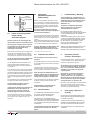
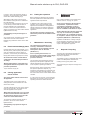
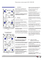
Bild 10 Außenerdung
Gehäuse-
innenwand
Erdungsplatte
Innenerdungs-
anschluss
Von außen herangeführte PE-Leitungen
sind auf die dafür vorgesehene PE-Klemme
am Flansch anzuschließen.
Ist eine seperate Außenerdung am Kunststoff-
gehäuse angebracht, darf dieser Anschluss mit
einer Leitung von max. 25mm² angeschlossen
werden.
Dieser Außenerdungsanschluss ist innen im Ge-
häuse für einen Kabelschuhanschluss mit einem
Loch für M6 ausgelegt (siehe auch Bild 10).
Achtung: Metallflansche, Metallplatten und
Metallverschraubungen müssen in den
Potentialausgleich miteinbezogen werden.
* z.Zt. nicht bescheinigt für Kategorie II D
6.4 Kunststoff-*,
Metallflanschplatten und
Außenerdung*
Müssen Flanschplatten demontiert werden
(z.B. zum Bohren von Einführungsöffnungen),
ist bei der Montage zur Aufrechterhaltung der
Mindestschutzart auf den korrekten Sitz der
Flanschplatte und den Sitz des Befestigungs-
bügels zu achten.

Cooper Crouse-Hinds GmbH
88
88
8
1 Technical data
1.1 Manual motor starters GHG 635
Marking acc. to 94/9/EC: II 2 G Ex e d II C T6 / T5*
II 2 D Ex tD A21 IP66 80° C
* Temperature class, see 1.6, page 9
EC type examination certificate: PTB 99 ATEX 1162
Rated voltage: 690 V, 50/60 Hz / 440 V DC
Rated current: up to 25 A
Short circuit back-up fuse: see point 1.4 and 1.5, page 4
AC 3 switching capacity: 690 V / 25 A
Thermal tripping characteristic: T II
Tripping time: see diagram 1, page 3, also point 1.7, page 5
Perm.storage temperature in original packing: -20° C up to +40° C (standard version)
Other temperatures possible for special versions.
Perm.storage temperature in original packing: -50° C to +80° C
Degree of protection acc. to EN/IEC 60529: IP 66 (standard version)
Insulation class acc. to EN/IEC 61140: I - device fulfil this requirement
II - with metal flange
Cable entries: (standard version)
0.1A - 6.3A 2 x M25 for cable Ø 8 - 17 mm
6.3A - 25.0A 2 x M32 for cable Ø 12 - 21 mm
with auxiliary contact / undervoltage release 1 x M25 in addition
Supply terminals: 2 x 0.75 - 4.0 mm² or 1 x 10 mm²
Test torques:
Cap nut of the cable entry M 25 3.5 Nm
Cap nut of the cable entry M 32 5.0 Nm
Cover screws 2.5 Nm
Terminals (main contacts) 3.5 Nm
Terminals (auxiliary contacts) 2.5 Nm
Terminals (under voltage contacts) 2.5 Nm
Weight:
Standard design approx. 2.45 kg
with auxiliary contact / undervoltage release approx. 2.55 kg
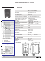
Manual motor starters up to 25A, GHG 635
Dimensions in mm
X = fixing dimensions
1.2 Auxiliary contact
Rated voltage: up to 400V AC
Rated current: up to 2 A
AC 15 switching capacity: 230 V / 2 A 400 V / 0.50 A
DC 13 switching capacity: 60 V / 2 A 230 V / 0.25 A
Perm. short circuit back-up fuse: max. 10 A gL
Terminals: 2 x 0.75 - 2.5 mm²
1.3 Undervoltage release
Rated voltage: 110 V, 230 V, 400 V, 500 V 50/60 Hz
Drop value: 35....75 % E
c
Starting value: >85 % E
c
Short circuit back-up fuse: not necessary
Terminals: 2 x 0.75 - 2.5 mm²
Manual motor starter GHG 635
Diagram 1
Tripping time
Multiple of setting current
Wiring diagram
1 = thermal tripping
2 = electromagnetic tripping

Cooper Crouse-Hinds GmbH
99
99
9
Manual motor starters up to 25A, GHG 635
1.4 Maximum rating current for short-circuit back-up fuse for max. 50 kA, if I
cc
> I
cs
*
Short circuit protection and max. back-up fuse
Setting range 240 V AC 400V AC 500V AC 690V AC
I
cs
gL, gG I
cs
gL, gG I
cs
gL, gG I
cs
gL, gG
0.10 A ......... 0.16 A
0.16 A ......... 0.25 A
0.25 A ......... 0.40 A
0.40 A ......... 0.63 A Short circuit proof
0.63 A ......... 1.00 A
1.00 A ......... 1.60 A no back-up fuse required, up to I
cc
= 50 kA
1.60 A ......... 2.50 A 40 kA 25A
2.50 A ......... 4.00 A 10 kA 40A
4.00 A ......... 6.30 A 40 kA 50A 7 kA 40A
6.30 A ......... 9.00 A 30 kA 80A 5 kA 50A
9.00 A ......... 12.50 A 27 kA 80A 4.5 kA 50A
12.50 A ......... 16.00 A 25 kA 100A 4 kA 50A
16.00 A ......... 20.00 A 22 kA 100A 3.5 kA 50A
20.00 A ......... 25.00 A 20 kA 125A 3 kA 50A
1.5 Maximum rating current for short-circuit back-up fuse for max. 100 kA, if I
cc
> I
cs
*
Short circuit protection and max. back-up fuse
Setting range 240 V AC 400V AC 500V AC 690V AC
I
cs
gL, gG I
cs
gL, gG I
cs
gL, gG I
cs
gL, gG
0.10 A ......... 0.16 A
0.16 A ......... 0.25 A
0.25 A ......... 0.40 A
0.40 A ......... 0.63 A Short circuit proof
0.63 A ......... 1.00 A
1.00 A ......... 1.60 A no back-up fuse required, up to I
cc
= 100 kA
1.60 A ......... 2.50 A 40 kA 25A
2.50 A ......... 4.00 A 60 kA 35 / 40A 10 kA 40A
4.00 A ......... 6.30 A 40 kA 50A 7 kA 40A
6.30 A ......... 9.00 A 30 kA 80A 5 kA 50A
9.00 A ......... 12.50 A 75 kA 80A 27 kA 80A 4.5 kA 50A
12.50 A ......... 16.00 A 60 kA 100A 25 kA 100A 4 kA 50A
16.00 A ......... 20.00 A 55 kA 100A 22 kA 100A 3.5 kA 50A
20.00 A ......... 25.00 A 50 kA 125A 20 kA 125A 3 kA 50A
1.6 Temperature class and conductor cross-section
Setting range Temperature class Min. conductor cross-section
Input Output
0.10 A ......... 1.60 A T 6 0.75 mm² 0.75 mm²
1.60 A ......... 2.50 A T 6 1.00 mm² 1.00 mm²
2.50 A ......... 4.00 A T 6 1.00 mm² 1.50 mm²
4.00 A ......... 9.00 A T 6 1.50 mm² 1.50 mm²
9.00 A ......... 12.50 A T 6 2.50 mm² 2.50 mm²
12.50 A ......... 20.00 A T 5 2.50 mm² 2.50 mm²
20.00 A ......... 25.00 A T 5 4.00 mm² 4.00 mm²
* I
cc
= prospective short-circuit current at installation location
I
cs
= Rated short-circuit breaking capacity

Cooper Crouse-Hinds GmbH
1010
1010
10
2 Safety instructions
The manual motor starters are not
suitable for zone 0 and Zone 20
hazardous areas.
The temperature class and type of
protection stated on the apparatus shall
be observed.
The requirements of the EN 61241-0 and -1
regarding excessive dust deposits and
temperature to be considered from the
user.
Modifications or changes to the manual
motor starters are not permitted.
They shall be used for their intended
purpose and shall be in a perfect and clean
state.
Only original COOPER Crouse-Hinds
parts may be used as replacements and
for repairs.
Repairs that affect the explosion protection
may only be carried out by COOPER
Crouse-Hinds or by a qualified electrician
in compliance with the respective national
regulations.
Prior to being put into operation, the
manual motor starters shall be checked in
accordance with the instructions as per
section 6.
Before initial operation, any foreign matter
shall be removed from the apparatus.
Warning:
Observe the terminal cross sections of the
manual motor starters in table 1.6, page 9.
The national safety rules and regulations
for the prevention of accidents, as well as
the safety instructions included in these
operating instructions, that, like this text,
are set in italics, shall be observed!
4 Field of application
The manual motor starters are suitable for use
in zone 1, 2 and 21, 22 hazardous areas acc.
to IEC 60079-10.
The enclosure materials employed, including
the exterior metal parts, are made of high-
quality materials which ensure a corrosion
protection and resistance to chemical
substances corresponding to the requirements
in a “normal industrial atmosphere”:
- glass-fibre reinforced polyester
- impact resistant polyamide
- special steel AISI 316 L
In case of use in an extremely aggresive
atmosphere, please refer to manufacturer.
Manual motor starters up to 25A, GHG 635
5 Application / Properties
The manual motor starters are used for the
protection of explosion-protected motors,
regardless of the explosion category, against
overload and phase failure.
The temperature class, explosion group,
tripping characteristic and permissible ambient
temperature can be found in the technical data.
Due to the AC 3 motor switching capacity of
the manual motor starter, a safe and reliable
isolation (switching) is also possible during
operation.
The use of an undervoltage trip prevents the
self-starting of the motor. In addition, the
undervoltage trip can be used for disconnecting
emergency circuits.
The auxiliary contact (optional) is mainly used
for signalling the operating state of the manual
motor starter.
To safeguard the manual motor starter against
unauthorized use, it can be locked in the OFF
position by means of 3 padlocking facilities
(shackle diameter of padlocks up to 5 mm).
The data according to sections 3 and 4
shall be taken into account during use.
Applications other than those described are
not permissible without a written
declaration of consent from Messrs.
COOPER Crouse-Hinds.
During operation the instructions stated in
section 7 of the operating instructions shall
be observed.
The sole responsibility with respect to the
suitability and proper use of the manual
motor starters with regard to the basic
requirements of these instructions (see
technical data) lies with the operator.
1.7 Tripping current and tripping time
Setting range Tripping current Tripping time in seconds for . . .-fold setting current
3-fold 4-fold 5-fold 6-fold 8-fold
0.10 A ......... 0.16 A 1.92 A 15.0 s 9.0 s 6.5 s 4.8 s 3.2 s
0.16 A ......... 0.25 A 3.00 A 16.0 s 10.0 s 6.8 s 5.2 s 3.6 s
0.25 A ......... 0.40 A 4.80 A 16.0 s 9.7 s 6.5 s 5.0 s 3.3 s
0.40 A ......... 0.63 A 7.56 A 17.0 s 10.2 s 7.3 s 5.7 s 3.9 s
0.63 A ......... 1.00 A 14.00 A 17.5 s 10.2 s 7.2 s 5.5 s 3.8 s
1.00 A ......... 1.60 A 22.40 A 17.0 s 10.0 s 7.1 s 5.6 s 4.0 s
1.60 A ......... 2.50 A 35.00 A 18.0 s 10.3 s 7.5 s 5.9 s 4.2 s
2.50 A ......... 4.00 A 60.00 A 18.4 s 11.5 s 8.1 s 6.4 s 4.6 s
4.00 A ......... 6.30 A 94.50 A 19.0 s 12.0 s 8.5 s 6.7 s 4.9 s
6.30 A ......... 9.00 A 135.00 A 18.2 s 11.5 s 7.9 s 6.0 s 3.8 s
9.00 A ......... 12.50 A 187.50 A 19.0 s 11.5 s 8.0 s 6.0 s 4.0 s
12.50 A ......... 16.00 A 240.00 A 19.5 s 11.5 s 7.5 s 5.4 s 3.3 s
16.00 A ......... 20.00 A 300.00 A 20.0 s 11.5 s 7.8 s 5.7 s 3.5 s
20.00 A ......... 25.00 A 375.00 A 20.0 s 10.4 s 7.0 s 5.0 s 3.2 s
3 Conformity with standards
The apparat is conform to the standards
specified in the EC-Declaration of conformity.
It has been designed, manufactured and
tested according to the state of the art and to
DIN EN ISO 9001.
94/9 EC: Equipment and protective systems
intended for use in potentially explosive
atmospheres.
The control units fulfil further requirements,
such as the EC directive on electromagnetic
compatibility (2004/108/EC)

Cooper Crouse-Hinds GmbH
1111
1111
11
6.2 Opening apparatus /
Electrical connection
Before opening the apparatus, it is
necessary to ensure that there is no voltage
or to take suitable protective measures.
The electrical connection of the may only
be carried out by specialists.
The properly bared conductors of cables shall
be connected with due regard to the
respective regulations.
To maintain the explosion protection,
conductors shall be connected with special
care.
The insulation shall reach up to the
terminal. The conductor itself shall not be
damaged.
The minimum and maximum conductor
cross sections that can be connected shall
be observed (see section 1.6, technical
data).
Manual motor starters up to 25A, GHG 635
6.1 Montage
The manual motor starter can be mounted
without opening the enclosure.
When the manual motor starters are mounted
directly onto the wall, they shall rest evenly
only on the fastening points provided for this
purpose.
The screw chosen shall fit the fixing hole (see
dimensional drawing) and shall not damage
the hole (e.g. use of a washer).
If the screws are overtightened, the
apparatus may be damaged.
The manual motor starters are suited for plug-
in mounting on COOPER Crouse-Hinds
apparatus holders, size 3, whereby they are
pushed into the guide groove from the top of
the apparatus holder. See the respective
mounting instructions.
6 Installation
The relevant national regulations(e.g. Elex V,
the equipment safety law for Germany) and
the generally recognized rules of engineering
apply for the installation and operation.
The improper installation and operation of
manual motor starters may result in the
invalidation of the guarantee.
Apparatus holder for wall- and channel
fixing, size 3
A = fixing points
for manual motor starter
A A
A A
A A
A A
Apparatus holder for pipe fixing, size 3
A = fixing point
for manual motor starter
All screws and/or nuts of connection
terminals, including those not in use, shall be
tightened down securely.
Excessive tightening may affect or damage
the connection.
The terminals are designed for the direct
connection of conductors with copper wires. If
multi- or fine-wire connecting cables are used,
the wire ends shall be handled according to
the applicable national and international
regulations (e.g. use of multicore cable ends).
The position of the terminals can be found in
the wiring diagram of the switch insert on
page 8, technical data.
To ensure a correct closing of the manual
motor starter, switching at the switch shaft of
the switch insert when the apparatus is open
is not permitted.
If, to facilitate the feeding of conductors into
the enclosure, the switch insert is snapped out
of the rail on the enclosure base by releasing
the catches (top or bottom on insert), it shall
be snapped back into position in the
enclosure base before the electrical
connection.
The end clamps on the DIN rail are used for
fixing the switch insert on the rail and shall
not be dismounted under any
circumstances.
The undervoltage trip is generally connected
to separate terminals(see wiring diagram on
page 8, technical data). Wiring of the
undervoltage trip according to the individual
application shall be carried out by the user.
6.3 Cable entries (KLE);
blanking plugs
Generally, only certified cable entries and
blanking plugs may be used.
Flexible cables shall be used with trumpet-
shaped cable glands or other suitable
entries with additional pull-relief.
When using cable entries with a degree of
protection that is lower than the IP protection
of the apparatus (see page 8), the degree of
IP protection for the complete unit is reduced.
The relevant mounting directives for cables
entries being used shall be observed

Cooper Crouse-Hinds GmbH
1212
1212
12
9 Disposal / Recycling
The respective valid national regulations for
waste disposal shall be observed when
disposing of apparatus.
To facilitate recycling of individual parts, parts
made of moulded plastic shall bear the
marking for the type of plastic used.
The product range is subject to changes and
additions.
8 Repairs / Overhaul /
ModificationModification
ModificationModification
Modification
Only original COOPER Crouse-Hinds parts
shall be used for carrying out repairs.
In the event of damage to the flameproof
encapsulation, replacement of these
components is mandatory. In case of
doubt, the respective apparatus shall be
sent to COOPER Crouse-Hinds for repair.
Repairs that affect the explosion protection
may only be carried out by COOPER
Crouse-Hinds or by a qualified electrician
in compliance with the respective national
regulations (EN 60079-17, EN 60079-19).
Apparatus modifications or design changes
are not permitted; excepted from this is the
fitting of additional cable entries within the
scope of the apparatus approvals.
7 Maintenance / Servicing
The valid national regulations for the
servicing / maintenance of electrical
apparatus for use in potentially explosive
atmospheres shall be observed
(EN 60079-17).
Prior to opening the enclosure, it is
necessary to ensure that the voltage supply
has been isolated or to take suitable
protective measures.
The necessary intervals between servicing
depend upon the specific application and
shall be stipulated by the operator according
to the respective operating conditions.
During servicing, above all, the parts on which
the explosion protection depend, (e.g.
intactness of the flameproof components, the
enclosure, the seals and cable entries), and
the reset function of the switch handle shall be
checked.
If, in the course of servicing, it is ascertained,
that repairs are necessary, section 8 of these
operating instructions shall be observed.
6.6 Putting into operation
Before putting the apparatus into operation,
the tests specified in the individual national
regulations shall be performed.
In addition to this, before being put into
operation, the correct functioning of the
apparatus and installation of the apparatus
shall be checked in accordance with these
operating instructions and other applicable
regulations.
The improper operation of manual motor
starters may result in the invalidation of the
guarantee.
6.5 Closing apparatus /
Cover closure
Any foreign matter shall be removed from
the apparatus.
The setting screw on the switch insert for
setting the rated current shall be set to the
rated motor current.
The switch handle on the cover of the manual
motor starter shall be in the position it had
when the apparatus was opened.
When fitting the apparatus cover, care shall
be taken to ensure that the switch shaft of
the switch insert engages correctly in the
carrier hole of the switch handle.
To ensure the required minimum degree of
protection, the cover screws shall be
tightened down.
Overtightening may impair the degree of
protection.
In order to ensure the minimum degree of
protection, any unused entry holes shall be
sealed with certified blanking plugs.
When fitting cable entries, care has to be
taken that the sealing inserts are suitable for
the cable diameter.
In the case of sealing inserts that are cut out,
it is necessary to ensure that the insert is
properly adapted to the cable diameter.
In order to ensure the required minimum
degree of protection, the cable entries shall be
tightened down securely.
Overtightening can impair the degree of
protection.
Any unused metric COOPER Crouse-Hinds
cable entries shall be sealed with the
blanking plug certified for these metric cable
entries.
Manual motor starters up to 25A, GHG 635
6.4 Plastic*and metalflange plates
If flange plates have to be dismantled, (e.g. to
drill entry holes), when replacing the plates, in
order to maintain the minimum degree of
protection, it is necessary to ensure that the
flange plate and the fixing clamp fit correctly.
PE conductors fed from outside shall be
connected to the PE terminal provided on
the flange.
Warning: Metal flanges, metal plates and
metal glands shall be incorporated in the
potential equalization.
*not yet certified for category IID

Cooper Crouse-Hinds GmbH
1313
1313
13
1 Caractéristiques techniques
1.1 Disjoncteurs moteur GHG 635
Marquage selon 94/9/CE: II 2 G Ex e d II C T6 / T5*
II 2 D Ex tD A21 IP66 80° C
* Classe de température voir point 1.6, page 4
Attestation d’examen CE de type: PTB 99 ATEX 1162
Tension nominale: 690 V, 50/60 Hz / 440V DC
Courant nominal: jusqu'à 25 A
Fusible de court-circuit: voir point 1.4 et 1.5, page 4
Puissance de coupure AC 3: jusqu'à 690 V / 25 A
Caractéristique du déclenchement thermique: T II
Temp s de déclenchement: voir diagramme 1, p..3, et point 1.7 p.5
Température ambiante admissible: -20°C à +40°C (modèles standard)
D’autres températures sont possibles avec des modèles spéciaux.
Temp. de stockage dans l’emballage original: -50° C à +80° C
Indice de protection selon EN/CEI 60529: IP 66 (modèles standard)
Classe d’isolation selon EN/CEI 61140: I - le dispositif remplis cette condition
II - avec plaque métalique
Entrées de câble (modèles standard)
0,1A jusqu'à 6,3A 2 x M25 pour câbles de Ø 8 - 17 mm
6,3A jusqu'à 25,0A 2 x M32 pour câbles de Ø 12 - 21 mm
avec contact auxiliaire /
déclencheur sur baisse de tension: 1 x M25 en supplément
Bornes de connexion: 2 x 0,75 - 4, 0 mm² ou 1 x 10 mm²
Couples de serrage testés:
Ecrou borgne bas de l’entrée de câble M 25 3,5 Nm
Ecrou borgne bas de l’entrée de câble M 32 5,0 Nm
Vis du couvercle 2,5 Nm
Bornes de connexion principaux contact 3,5 Nm
Bornes de connexion auxiliaires contact 2,5 Nm
Bornes de connexion déclencheur à min.de tension 2,5 Nm
Poids à vide:
modèle de standard env. 2,45 kg
avec contacts aux. /déclencheur sur baisse de tension env. 2,55 kg
Disjoncteurs moteur jusqu'à 25A, GHG 635
Dimensions en mm
X = dimensions de fixation
1.2 Contacts auxiliaires
Tension nominale: jusqu'à 400 V AC
Courant nominal: jusqu'à 2 A
Puissance de coupure AC 15: 230V / 2 A 400 V / 0,5 A
Puissance de coupure DC 13: 60 V / 2 A 230V / 0,25 A
Fusible de court-circuit adm. placé en amont: 10 A gL maxi
Bornes de connexion: 2 x 0,75 - 2,5 mm²
1.3 Déclencheur à minimum de tension
Tension nominale: 110 V, 230 V, 400 V, 500 V 50/60 Hz
Valeur de chute: 35....75 % von U
c
Valeur d'actionnement: >85 % von U
c
Fusible de court-circuit adm. placé en amont: non nécessaire
Bornes de connexion: 2 x 0,75 - 2,5 mm²
Disjoncteurs moteur GHG 635
Diagramme 1
Multiple de l'intensité reglée
Schéma des connexions
1 = déclenchement thermique
2 = déclenchement électromagnétique
Temps de déclenchement

Cooper Crouse-Hinds GmbH
1414
1414
14
1.4 Courant max. de court-circuit du fusible pour max. 50 kA, pour Icc > Ics *
Résistance aux court-circuits et fusible maximum placé en amont
Plage de réglage 240 V AC 400V AC 500V AC 690V AC
I
cs
gL, aM I
cs
gL, aM I
cs
gL, aM I
cs
gL, aM
0,10 A ......... 0,16 A
0,16 A ......... 0,25 A
0,25 A ......... 0,40 A
0,40 A ......... 0,63 A Résistant aux courts-circuits
0,63 A ......... 1,00 A
1,00 A ......... 1,60 A fusible placé en amont non nécessaire jusqu'à I
cc
= 50 kA
1,60 A ......... 2,50 A 40 kA 25A
2,50 A ......... 4,00 A 10 kA 40A
4,00 A ......... 6,30 A 40 kA 50A 7 kA 40A
6,30 A ......... 9,00 A 30 kA 80A 5 kA 50A
9,00 A ......... 12,50 A 27 kA 80A 4,5 kA 50A
12,50 A ......... 16,00 A 25 kA 100A 4 kA 50A
16,00 A ......... 20,00 A 22 kA 100A 3,5 kA 50A
20,00 A ......... 25,00 A 20 kA 125A 3 kA 50A
1.5 Courant max. de court-circuit du fusible pour max. 100 kA, pour Icc > Ics *
Résistance aux court-circuits et fusible maximum placé en amont
Plage de réglage 240 V AC 400V AC 500V AC 690V AC
I
cs
gL, aM I
cs
gL, aM I
cs
gL, aM I
cs
gL, aM
0,10 A ......... 0,16 A
0,16 A ......... 0,25 A
0,25 A ......... 0,40 A
0,40 A ......... 0,63 A Résistant aux courts-circuits
0,63 A ......... 1,00 A
1,00 A ......... 1,60 A fusible placé en amont non nécessaire jusqu'à I
cc
= 100 kA
1,60 A ......... 2,50 A 40 kA 25A
2,50 A ......... 4,00 A 60 kA 35 / 40A 10 kA 40A
4,00 A ......... 6,30 A 40 kA 50A 7 kA 40A
6,30 A ......... 9,00 A 30 kA 80A 5 kA 50A
9,00 A ......... 12,50 A 75 kA 80A 27 kA 80A 4,5 kA 50A
12,50 A ......... 16,00 A 60 kA 100A 25 kA 100A 4 kA 50A
16,00 A ......... 20,00 A 55 kA 100A 22 kA 100A 3,5 kA 50A
20,00 A ......... 25,00 A 50 kA 125A 20 kA 125A 3 kA 50A
1.6 Classe de température et section de transversale du conducteur
Plage de réglage Classe de température Section transversale min. du conducteur
Entrée Sortie
0,10 A ......... 1,60 A T 6 0,75 mm² 0,75 mm²
1,60 A ......... 2,50 A T 6 1,00 mm² 1,00 mm²
2,50 A ......... 4,00 A T 6 1,00 mm² 1,50 mm²
4,00 A ......... 9,00 A T 6 1,50 mm² 1,50 mm²
9,00 A ......... 12,50 A T 6 2,50 mm² 2,50 mm²
12,50 A ......... 20,00 A T 5 2,50 mm² 2,50 mm²
20,00 A ......... 25,00 A T 5 4,00 mm² 4,00 mm²
* I
cc
= courant de court-circuit prévu sur le lieu d’installation
I
cs
= puissance de coupure du court-circuit mesuré
Disjoncteurs moteurs jusqu'à 25A, GHG 635

Cooper Crouse-Hinds GmbH
1515
1515
15
2 Consignes de sécurité
L e disjoncteur moteur ne convient pas à
l’emploi dans la zone 0 et zone 20.
Le groupe d’explosion et la
classe de température marqués
sur les appareils devront être respectés.
Les exigences des EN 61241-0 et -1 en ce
qui concerne des dépôts de poussière
démesurés et une température doivent
être considérées par I’utilisateur.
Il n’est pas permis de transformer ou de
modifier les disjoncteurs moteurs.
Seuls des appareils intacts et en parfait
état de marche devront être employés
pour la fonction qui leur est dévolue.
Seules des pièces de rechange homolo-
guées d’origine COOPER Crouse-Hinds
devront être utilisées comme remplacement
et pour des réparations.
Des réparations portant sur la protection
contre l’explosion, ne devront être
exécutées que par COOPER Crouse-Hinds
ou par un électricien qualifié en conformité
avec la règlementation nationale en vigueur.
Avant la mise en service, les disjoncteurs
moteurs doivent être vérifiés selon les
instructions exposées donnée dans la
section 6.
Avant la première mise en service, tout
corps étranger doit être ôté de l'appareil.
Attention:
Respecter les sections de raccord du
disjoncteur moteur selon le point 1.6, page 15.
Respectez les prescriptions nationales de
sécurité et de prévoyance contre les
accidents ainsi que les consignes de
sécurité qui suivent dans ce mode d’emploi
et qui sont mises en italique comme ce texte.
Disjoncteurs moteur jusqu'à 25A, GHG 635
4 Domaine d’utilisation
Les disjoncteurs moteur conviennent à
l’emploi en zones 1, 2 et 21, 22 d’une
atmosphère explosive selon CEI 60079-10.
Pour l’enveloppe et les pièces métalliques
extérieures, des matières de qualité supérieure
qui assurent une protection appropriée contre
la corrosion et une résistance contre des
agents chimiques en “atmosphère industrielle
normale”ont été employées:
- polyester chargé verre
- polyamide anti-choc
- acier spécial AISI 316 L
En cas d‘utilisation en atmosphère
extrèmement corrosive, vous pouvez obtenir
des informations complémentaires sur la
résistance chimique des plastiques utilisés
chez la succursale Cooper Crouse-Hinds de
votre région.
5 Utilisation / Propriétés
Les disjoncteurs moteur servent à protéger les
moteurs Ex pour tout type de protection
contre
l’explosion d’éventuelles surcharges et pertes
de phase. Les informations relatives à la
classe de température, au groupe d’explosion,
aux caractéristiques de déclenchement, à la
température ambiante admise ainsi que le
diagramme de déclenchement figurent dans
les données techniques.
Avec la puissance de coupure AC 3 du
disjoncteur moteur, une disjonction peut être
effectuée en toute sécurité pendant le
fonctionnement de l’installation électrique.
L’utilisation d’un déclencheur sur baisse de
tension empêche un demarrage indépendant
du moteur. En outre, le déclencheur sur baisse
de tension peut être employé pour mettre
hors-circuit sur le mode arrêt d’urgence.
Le contact auxiliaire (en option) sert
principalement à donner un signal relatif à
l’état de fonctionnent du disjoncteur moteur.
Le disjoncteur moteur peut, en position OFF,
être doté de trois cadenas, prévenant ainsi
tout risque de mise hors-tension non autorisée
(diamètre de l’étrier : jusqu’à 5mm).
Pour l’emploi, les consignes des sections 3
et 4 devront être respectées.
Des emplois autres que ceux décrits ne
sont admis qu’avec l’approbation écrite
de COOPER Crouse-Hinds. Lors de
l’utilisation, les instructions selon point 7 de
ce mode d’emploi doivent être respectées.
Seul l’utilisateur est responsable de
l’emploi comme prévu de disjoncteur
moteur, en tenant compte des conditions
générales existant dans l’établissement
(voir Caractéristiques techniques).
1.7 Courant et temps de déclenchement
Plage de réglage Courant de Temps de déclenchement en sec. selon la multiplicité du réglage du
courant déclenchement 3 fois 4 fois 5 fois 6 fois 8 fois
0,10 A ......... 0,16 A 1,92 A 15,0 s 9,0 s 6,5 s 4,8 s 3,2 s
0,16 A ......... 0,25 A 3,00 A 16,0 s 10,0 s 6,8 s 5,2 s 3,6 s
0,25 A ......... 0,40 A 4,80 A 16,0 s 9,7 s 6,5 s 5,0 s 3,3 s
0,40 A ......... 0,63 A 7,56 A 17,0 s 10,2 s 7,3 s 5,7 s 3,9 s
0,63 A ......... 1,00 A 14,00 A 17,5 s 10,2 s 7,2 s 5,5 s 3,8 s
1,00 A ......... 1,60 A 22,40 A 17,0 s 10,0 s 7,1 s 5,6 s 4,0 s
1,60 A ......... 2,50 A 35,00 A 18,0 s 10,3 s 7,5 s 5,9 s 4,2 s
2,50 A ......... 4,00 A 60,00 A 18,4 s 11,5 s 8,1 s 6,4 s 4,6 s
4,00 A ......... 6,30 A 94,50 A 19,0 s 12,0 s 8,5 s 6,7 s 4,9 s
6,30 A ......... 9,00 A 135,00 A 18,2 s 11,5 s 7,9 s 6,0 s 3,8 s
9,00 A ......... 12,50 A 187,50 A 19,0 s 11,5 s 8,0 s 6,0 s 4,0 s
12,50 A ......... 16,00 A 240,00 A 19,5 s 11,5 s 7,5 s 5,4 s 3,3 s
16,00 A ......... 20,00 A 300,00 A 20,0 11,5 s 7,8 s 5,7 s 3,5 s
20,00 A ......... 25,00 A 375,00 A 20,0 s 10,4 s 7,0 s 5,0 s 3,2 s
3 Conformité avec les normes
Les boîtes à bornes ont été conçues,
fabriquées et contrôlées suivant
DIN EN ISO 9001.
Les Appareils sont conformes aux normes
reprises dans la déclaration de conformité.
94/9 CE: Appareils et systèmes de protection
destinés à être utilisés en atmosphère
explosible.
De Appareils de commande répondent à
d’autres exigences comme par exemple,
celles de la directive CE “Compatibilité
électromagnétique” (2004/108/CEE).

Cooper Crouse-Hinds GmbH
1616
1616
16
6.26.2
6.26.2
6.2
OuverturOuvertur
OuverturOuvertur
Ouvertur
e de l’appare de l’appar
e de l’appare de l’appar
e de l’appar
eil /eil /
eil /eil /
eil /
RaccorRaccor
RaccorRaccor
Raccor
dement électriquedement électrique
dement électriquedement électrique
dement électrique
Avant ouverture de l’enveloppe, mettre
l’appareil hors-tension et prendre les
mesures préventives appropriées.
Le raccordement électrique de l’appareil ne
doit se faire que par un personnel qualifié.
Le raccordement des câbles dénudés se fera
selon les règlements correspondants
Afin de maintenir le mode de protection, la
connexion des conducteurs doit se faire
très soigneusement.
L’isolation doit couvrir le conducteur
jusqu’à la borne. Le conducteur lui-même
ne doit pas être endommagé.
Les sections minimales et maximales
admissibles des conducteurs doivent être
respectées (voir caractéristiques
techniques, point 1.6).
Disjoncteurs moteur jusqu'à 25A, GHG 635
6.1 Montage
Le montage des disjoncteurs moteurs peut se
faire sans ouvrir l’enveloppe.
Dans le cas d'un montage directement au
mur, les disjoncteurs moteurs ne doivent
reposer au niveau du mur que sur les points
de fixation prévus.
La vis choisie doit être en rapport avec le trou
de fixation (voir plan coté) et ne doit pas
avarier le trou (par ex. emploi d’une rondelle).
L'appareil doit être fixé en diagonale avec au
moins 2 vis
Un serrage excessif des vis de fixation peut
endommager l’appareil.
Le montage des disjoncteurs moteur se fait
sur les plaques de fixation COOPER Crouse-
Hinds, taille 3 par insertion (par le haut) dans
les encoches prévues à cet effet. Reportez
vous à la notice de montage correspondante
6 Installation
Pour l’installation et l’exploitation de ces
appareils, la règlementation nationale en
vigueur (en Allemagne par ex. ElexV, loi de
sécurité des appareils) ainsi que les règles de
la technique généralement reconnues devront
être respectées.
L’installation ou l’utilisation incorrecte de
ces disjoncteurs moteurs à bornes peut
entraîner la perte de la garantie.
Plaque de fixation au mur/
sur grillage, taille 3
A = points de fixation pour disjoncteurs
moteur
A A
A A
A A
A A
Plaque de fixation sur tube, taille 3
A = points de fixation pour disjoncteurs
moteur
Toutes les vis et/ou écrous des bornes de
connexion, ainsi que celles des bornes non
utilisées, doivent être serrées à fond.
Un serrage excessif des vis peut
endommager l’appareil.
Les bornes sont prévues pour le
raccordement de conducteurs en cuivre. En
cas d’utilisation de câbles de connexion
multifilaires ou à fils de petit diamètre, les
extrémités de fil doivent être traité selon la
règlementation nationale et internationale
applicable (par ex. emploi des embouts).
La disposition des bornes de connexion est
représentée par la figure des connexions du
socle et par celle de la page 13 (Caractéristiques
techniques).
Afin de s’assurer une fermeture correcte du
disjoncteur moteur, une commutation de l’axe
du socle n’est pas permise.
Si, du fait de l’introduction des conducteurs
dans l’enveloppe, le socle venait à être
légèrement délogé (vers le haut ou le bas) de
son rail de fixation, celui-ci devrait être remis
en place correctement sur ce rail avant toute
connexion électrique.
Le support du rail sert à la fixation du socle
de l’interrupteur sur ce dernier et ne doit en
aucun cas être démonté.
Le raccordement du déclencheur sur basse
tension se fait, de manière générale, sur des
bornes à part (voir plan de raccordement,
page 3 - Caractéristiques techniques). Le
câblage du déclencheur sur basse tension,
variable selon l’utilisation, sera effectué par
l’utilisateur lui même.
6.3 Entrées de câble /
Bouchons de fermeture
Généralement, seuls des bouchons de
fermeture et des entrées de câble certifiés
doivent être utilisés.
Pour des câbles flexibles il faudra utiliser
des presse-étoupes en forme de trompette
ou d’autres entrées appropriées avec
décharge de traction supplémentaire.
Lorsque des entrées de câble avec un indice
de protection IP inférieur à celui de les
disjoncteurs moteurs sont employées (voir
page 3), l’indice de protection IP de
l’ensemble sera réduit.
Les directives pour le montage qui
s’appliquent aux entrées de câble utilisées,
doivent être respectées.

Cooper Crouse-Hinds GmbH
1717
1717
17
9 Évacuation des déchets/
Recyclage
Lors de l’évacuation de ce matériel électrique,
la règlementation nationale respective en
vigueur devra être respectée.
Pour faciliter la réutilisation des composants
individuels, les pièces en plastique ont été
repérées de la marque distinctive de la
matière plastique employée.
Sous réserve de modification ou
d’informations supplémentaires.
8 Réparations / Remise en état
Des réparations ne doivent être exécutées
qu’à l’aide des pièces de rechange d’origine
COOPER Crouse-Hinds.
En cas de défauts sur l’enveloppe
antidéflagrante, seul un remplacement est
admissible. Dans le doute, l’appareil
défectueux devra être renvoyé à COOPER
Crouse-Hinds pour être réparé.
Des réparations qui portent sur la
protection contre l’explosion, ne devront
être exécutées que par COOPER Crouse-
Hinds ou par un électricien qualifié en
conformité avec la règlementation
nationale en vigueur.
(EN 60079-17, EN 60079-19).
Il n’est pas permis de transformer ou de
modifier ces appareils, sauf pour le montage
des entrées de câble supplémentaires en
conformité avec leur homologation.
7 Maintien/Entretien
La règlementation nationale en vigueur
pour le maintien et l’entretien du matériel
électrique pour atmosphère explosive doit
être respectée (EN 60079-17).
Avant ouverture de l’enveloppe, mettre
l’appareil hors-tension et prendre les
mesures préventives appropriées.
La fréquence des travaux d’entretien requis
dépendent de l’emploi spécifique et devront
donc être fixés par l’utilisateur en tenant
compte des conditions d’utilisation.
Lors de l’entretien des disjoncteurs, surtout
les composants qui sont essentiels à leur
mode de protection contre l’explosion, doivent
être vérifiés (par ex. intégrité de composant
antidéflagrants et du boitier, efficacité des
joints de couvercle et resserrement des
entrées de câble). La fonction de remise du
garrot de commutation doit également être
vérifiée
Si, lors d’un entretien, on constate que des
travaux de remise en état sont nécessaires, il
faudra suivre le point 8 de ce mode d’emploi.
6.6 Mise en service
Avant la mise en service de l’appareil, les
vérifications spécifiées dans les règlements
nationaux individuels devront être exécutées.
De plus, il faudra vérifier son fonctionnement
et installation corrects en conformité avec ce
mode d’emploi et avec d’autres règlements
applicables.
L’utilisation incorrecte de ces
commutateurs peut annuler la garantie.
6.5 Fermeture du dispositif
Tout corps étranger doit être ôte du
dispositif.
La vis de réglage du courant nominal du socle
s’ajuste en fonction du courant nominal du
moteur.
Le commutateur du couvercle du disjoncteur
moteur doit être dans la même position que
lors de l’ouverture de l’enveloppe.
Lors de la fermeture du couvercle, on
s’assurera que l’axe est introduit
correctement dans l’ouverture prévue.
Afin de garantir l’indice de protection
minimum requis, on s’assurera que les vis du
couvercle sont bien serrées.
Un serrage excessif des vis peut
endommager l’appareil.
Les entrées non utilisées doivent être fermées
avec un bouchon de fermeture certifié pour établir
l’indice de protection minimum.
Lors du montage des entrées de câble il
faudra veiller à ce que des garnitures
d’étanchéité correspondant au diamètre du
câble soient utilisées.
Si les garnitures doivent être coupées sur
mesure, il faudra veiller à ce que celles-ci
s’adaptent parfaitement au diamètre du câble.
Les entrées de câble doivent être serrées à
fond pour maintenir l’indice de protection
minimum.
Au cas où elles seraient forcées, cela
pourrait être nuisible à l’indice de
protection.
Toutes les entrées de câble métriques
COOPER Crouse-Hinds non utilisées doivent
être fermées avec un bouchon de fermeture
certifié pour des entrées de câble métriques.
Disjoncteurs moteur jusqu'à 25A, GHG 635
6.4 Plaques à brides
Si les plaques à brides doivent être
démontées (pour percage d’entrées de câble,
par exemple) il faudra veiller lors du montage
au maintien de l’indice de protection en
replacant correctement la plaque ainsi que les
brides de serrage.
Des conducteurs PE amenés de l’extérieur
doivent être connectés à la borne PE
prévue à cet effet sur la bride.
Attention: les brides métalliques, les
plaques de fond métalliques et les presse-
étoupe métalliques doivent être reliés au
même potentiel.
* pour le moment, pas encore certifié Catégorie IID

Cooper Crouse-Hinds GmbH
1818
1818
18

Cooper Crouse-Hinds GmbH
1919
1919
19

COOPER Crouse-Hinds GmbH
Neuer Weg-Nord 49
D 69412 Eberbach / Germany
Fone 0049 (0) 6271 / 806 - 500
Fax 0049 (0) 6271 / 806 - 476
Internet: www.ceag.de
E-Mail: [email protected]
GHG 630 7011 P0003 D/E/F (E) / Auflage /40.08/ Zi
&=7HQWRQiYRGNSRXåLWtVLPåHWHY\åiGDW
YHVYpPPDWHĜVNpPMD]\FHXSĜtVOXãQpKR
]DVWRXSHQtVSROHþQRVWL&RRSHU&URXVH
+LQGV&($*YHYDãt]HPL
'.0RQWDJHYHMOHGQLQJHQNDQRYHUVWWHVWLO
DQGUH(8VSURJRJUHNYLUHUHVKRV'HUHV
&RRSHU&URXVH+LQGV&($*OHYHUDQG¡U
((QFDVRQHFHVDULRSRGUiVROLFLWDUGHVX
UHSUHVHQWDQWH&RRSHU&URXVH+LQGV&($*
HVWDVLQVWUXFFLRQHVGHVHUYLFLRHQRWURLGLRPD
GHOD8QLRQ(XURSHD
(676HGDNDVXWXVMXKHQGLWRPDULLJLNHHOHV
Y}LWHNVLGDRPDULLJLVDVXYDVWDVMDRPDVHVW
&RRSHU&URXVH+LQGVL&($*HVLQGXVHVW
),17DUYLWWDHVVDWlPlQNl\WW|RKMHHQNllQQ|V
RQVDDWDYLVVDWRLVHOOD(8QNLHOHOOl7HLGlQ
&RRSHU&URXVH+LQGV&($*HGXVWDMDOWDQQH
*5ǼĮȞȤȡİȚĮıșİȚİIJĮȡĮıȘIJȦȞȠįȘȖȚȦȞȤȡȘıİ
ȦȢıİĮȜȜȘȖȜȦııĮIJȘȢǼǼʌȠȡİȚȞĮȗȘIJȘșİȚĮʌȠ
IJȠȞǹȞIJȚʌȡȠıȦʌȠIJȘȢ&RRSHU&URXVH
+LQGV&($*³
+$NH]HOpVL~WPXWDWyWD]DGRWWRUV]iJ
Q\HOYpQD&RRSHU&URXVH+LQGV&($*FpJ
KHO\LNpSYLVHOHWpQLJpQ\HOKHWLPHJ
,6HGHVLGHUDWHODWUDGX]LRQHGHOPDQXDOH
RSHUDWLYRLQXQDOWUDOLQJXDGHOOD&RPXQLWj
(XURSHDSRWHWHULFKLHGHUODDOYRVWUR
UDSSUHVHQWDQWH&RRSHU&URXVH+LQGV&($*
/7âLRVQDXGRMLPRLQVWUXNFLMRVLãYHUVWRVƳ-njVǐ
JLPWąMąNDOEąJDOLWHSDUHLNDODXWLDWVDNLQJRMH
&RRSHU&URXVH+LQGV&($*DWVWRY\EHMHVDYR
ãDO\MH
/9âRHNVSOXDWƗFLMDVLQVWUXNFLMXYDOVWVYDORGƗ
YDUDWSLHSUDVƯWMXVXYDOVWVDWELOGƯJDMƗ&RRSHU
&URXVH+LQGV&($*SƗUVWƗYQLHFƯE
Ɨ
0-LVWJƫXMLWROEXGDQLOPDQZDOILOOLQJZD
QD]]MRQDOLWDJƫKRPPLQJƫDQGLUUDSSUHĪHQWDQW
WD&RRSHU&URXVH+LQGV&($*ISDMMLĪKRP
1/,QGLHQQRRG]DNHOLMNNDQGHYHUWDOLQJYDQ
GH]HJHEUXLNVLQVWUXFWLHLQHHQDQGHUH(8WDDO
ZRUGHQRSJHYUDDJGELM8Z&RRSHU&URXVH
+LQGV&($*YHUWHJHQZRRUGLJLQJ
36HIRUQHFHVViULDDWUDGXomRGHVWDV
LQVWUXo}HVGHRSHUDomRSDUDRXWURLGLRPDGD
8QLmR(XURSHLDSRGHVROLFLWDODMXQWRGRVHX
UHSUHVHQWDQWH&RRSHU&URXVH+LQGV&($*
3/1LQLHMV]ąLQVWUXNFMrREVáXJLZRGSRZLHGQLHM
ZHUVMLMĊ]\NRZHMPRĪQD]DPyZLüZ
SU]HGVWDZLFLHOVWZLHILUP\&RRSHU&URXVH
+LQGV&($*QDGDQ\NUDM
6(Q|YHUVlWWQLQJDYGHQQDPRQWDJHRFK
VN|WVHOLQVWUXNWLRQWLOODQQDW(8VSUnNNDQYLG
EHKRYEHVWlOODVIUnQ(U&RRSHU&URXVH
+LQGV&($*UHSUHVHQWDQW
6.7HQWRQiYRGQDREVOXKX9iPYR9DãRP
URGQRPMD]\NXSRVN\WQH]DVW~SHQLHVSRORþQRVWL
&RRSHU&URXVH+LQGV&($*YR9DãHMNUDMLQH
6/21DYRGLOD]DXSRUDERY9DãHPMH]LNX
ODKNR]DKWHYDWHSULSULVWRMQHP]DVWRSQLãWYX
SRGMHWMD&RRSHU&URXVH+LQGV&($*Y9DãL
GUåDYL
-
 1
1
-
 2
2
-
 3
3
-
 4
4
-
 5
5
-
 6
6
-
 7
7
-
 8
8
-
 9
9
-
 10
10
-
 11
11
-
 12
12
-
 13
13
-
 14
14
-
 15
15
-
 16
16
-
 17
17
-
 18
18
-
 19
19
-
 20
20


Cooper GHG 635 Operating Instructions Manual
- Taper
- Operating Instructions Manual
dans d''autres langues
- English: Cooper GHG 635
- Deutsch: Cooper GHG 635
Autres documents
-
Eaton Crouse-Hinds GHG 61 R Series Operating Instructions Manual
-
Eaton GHG29 Control Switches Mode d'emploi
-
-
-
-
-
-
Eaton GHG 511 Mode d'emploi
-
-