
Part No. 303321-A Rev. 00
July 1998
Voice Gateway 4000
Upgrade Guide

ii
303321-A Rev. 00
4401 Great America Parkway 8 Federal Street
Santa Clara, CA 95054 Billerica, MA 01821
Copyright © 1998 Bay Networks, Inc.
All rights reserved. Printed in the USA. July 1998.
The information in this document is subject to change without notice. The statements, configurations, technical data,
and recommendations in this document are believed to be accurate and reliable, but are presented without express or
implied warranty. Users must take full responsibility for their applications of any products specified in this document.
The information in this document is proprietary to Bay Networks, Inc.
Trademarks
Bay Networks is a registered trademark and the Bay Networks logo is a trademark of Bay Networks, Inc.
All other trademarks and registered trademarks are the property of their respective owners.
Restricted Rights Legend
Use, duplication, or disclosure by the United States Government is subject to restrictions as set forth in subparagraph
(c)(1)(ii) of the Rights in Technical Data and Computer Software clause at DFARS 252.227-7013.
Notwithstanding any other license agreement that may pertain to, or accompany the delivery of, this computer
software, the rights of the United States Government regarding its use, reproduction, and disclosure are as set forth in
the Commercial Computer Software-Restricted Rights clause at FAR 52.227-19.
Statement of Conditions
In the interest of improving internal design, operational function, and/or reliability, Bay Networks, Inc. reserves the
right to make changes to the products described in this document without notice.
Bay Networks, Inc. does not assume any liability that may occur due to the use or application of the product(s) or
circuit layout(s) described herein.

303321-A Rev. 00 iii
USA Requirements Only
Federal Communications Commission (FCC) Compliance Notice: Radio Frequency Notice
Note: This equipment has been tested and found to comply with the limits for a Class A digital device, pursuant to
Part 15 of the FCC rules. These limits are designed to provide reasonable protection against harmful interference
when the equipment is operated in a commercial environment. This equipment generates, uses, and can radiate radio
frequency energy. If it is not installed and used in accordance with the instruction manual, it may cause harmful
interference to radio communications. Operation of this equipment in a residential area is likely to cause harmful
interference, in which case users will be required to take whatever measures may be necessary to correct the
interference at their own expense.
European Requirements Only
EN 55 022 Statement
This is to certify that the Bay Networks Voice Gateway 4000 is shielded against the generation of radio interference in
accordance with the application of Council Directive 89/336/EEC, Article 4a. Conformity is declared by the
application of EN 55 022 Class A (CISPR 22).
Warning: This is a Class A product. In a domestic environment, this product may cause radio interference, in which
case, the user may be required to take appropriate measures.
EC Declaration of Conformity
This product conforms (or these products conform) to the provisions of Council Directive 89/336/EEC and
73/23/EEC. The Declaration of Conformity is available on the Bay Networks World Wide Web site at
www.baynetworks.com.
Japan/Nippon Requirements Only
Voluntary Control Council for Interference (VCCI) Statement
Voluntary Control Council for Interference (VCCI) Statement
This is a Class A product based on the standard of the Voluntary Control Council for Interference by Information
Technology Equipment (VCCI). If this equipment is used in a domestic environment, radio disturbance may arise.
When such trouble occurs, the user may be required to take corrective actions.

iv 303321-A Rev. 00
Canada Requirements Only
Canadian Department of Communications Radio Interference Regulations
This digital apparatus (Voice Gateway 4000) does not exceed the Class A limits for radio-noise emissions from digital
apparatus as set out in the Radio Interference Regulations of the Canadian Department of Communications.
Règlement sur le brouillage radioélectrique du ministère des Communications
Cet appareil numérique (Voice Gateway 4000) respecte les limites de bruits radioélectriques visant les appareils
numériques de classe A prescrites dans le Règlement sur le brouillage radioélectrique du ministère des
Communications du Canada.
Canada CS-03 Rules and Regulations
Notice: The Industry Canada label identifies certified equipment. This certification means that the equipment meets
telecommunications network protective, operational and safety requirements as prescribed in the appropriate Terminal
Equipment Technical Requirements document(s). The Department does not guarantee the equipment will operate to
the user’s satisfaction.
Before installing this equipment, users should ensure that it is permissible to be connected to the facilities of the local
telecommunications company. The equipment must also be installed using an acceptable method of connection. The
customer should be aware that compliance with the above conditions may not prevent the degradation of service in
some situations.
Repairs to certified equipment should be coordinated by a representative designated by the supplier. Any repairs or
alterations made by the user to this equipment, or equipment malfunctions, may give the telecommunications
company cause to request the user to disconnect the equipment.
Users should ensure for their own protection that the electrical ground connections of the power utility, telephone lines
and internal metallic water pipe system, if present, are connected together. This precaution may be particularly
important in rural areas.
Caution: Users should not attempt to make such connections themselves, but should contact the appropriate electric
inspection authority, or electrician, as appropriate.
Notice: For equipment using loopstart lines, please note that the Ringer Equivalence Number (REN) assigned to each
terminal device provides an indication of the maximum number of terminals allowed to be connected to a telephone
interface. The termination on an interface may consist of any combination of devices subject only to the requirement
that the sum of the Ringer Equivalence Numbers of all the devices does not exceed 5. The REN is located on the “FCC
Rules Part 68” label located on the bracket of the module, or on the back of the unit.
Canada CS-03 -- Règles et règlements
Av is : L'étiquette d'Industrie Canada identifie le matériel homologué. Cette étiquette certifie que le matériel est
conforme aux normes de protection, d'exploitation et de sécurité des réseaux de télécommunications, comme le
prescrivent les documents concernant les exigences techniques relatives au matériel terminal. Le Ministère n'assure
toutefois pas que le matériel fonctionnera à la satisfaction de l'utilisateur.
Avant d'installer ce matériel, l'utilisateur doit s'assurer qu'il est permis de le raccorder aux installations de l'entreprise
locale de télécommunication. Le matériel doit également être installé en suivant une méthode acceptée de
raccordement. L'abonné ne doit pas oublier qu'il est possible que la conformité aux conditions énoncées ci-dessus
n'empêche pas la dégradation du service dans certaines situations.
Les réparations de matériel homologué doivent être coordonnées par un représentant désigné par le fournisseur.
L'entreprise de télécommunications peut demander à l'utilisateur de débrancher un appareil à la suite de réparations ou
de modifications effectuées par l'utilisateur ou à cause de mauvais fonctionnement.
Pour sa propre protection, l'utilisateur doit s'assurer que tous les fils de mise à la terre de la source d'énergie électrique,
des lignes téléphoniques et des canalisations d'eau métalliques, s'il y en a, sont raccordés ensemble. Cette précaution
est particulièrement importante dans les régions rurales.

303321-A Rev. 00 v
Avertissement: L'utilisateur ne doit pas tenter de faire ces raccordements lui-même; il doit avoir recours à un service
d'inspection des installations électriques, ou à un électricien, selon le cas.
Av is: Veuillez prendre note que pour tout appareillage supportant des lignes de type “loopstart,” l'indice d'équivalence
de la sonnerie (IES) assigné à chaque dispositif terminal indique le nombre maximal de terminaux qui peuvent être
raccordés à une interface. La terminaison d'une interface téléphonique peut consister en une combinaison de quelques
dispositifs, à la seule condition que la somme d'indices d'équivalence de la sonnerie de tous les dispositifs n'excède pas
5. Le REN figure sur l’étiquette “FCC Rules Part 68” située sur le support du module ou à l’arrière de l’unité.
FCC Part 68 Compliance Statement
This equipment complies with Part 68 of FCC Rules. All direct connections to telephone network lines must be made
using standard plugs and jacks compliant with FCC Part 68. Please note the following:
1. You are required to request service from the telephone company before you connect the unit to a network. When
you request service, you must provide the telephone company with the following data:
• When you request T1 Service, you must provide the telephone company with
-- The Facility Interface Code
Provide the telephone company with all the codes below:
- 04DU9-BN (1.544 MB, D4 framing format)
- 04DU9-DN (1.544 MB, D4 framing format with B8ZF coding)
- 04DU9-1KN (1.544 MB, ESF framing format)
- 04DU9-1SN (1.544 MB, ESF framing format with B8ZF coding)
- 04DU9-1ZN (1.544 MB, ANSI ESF and ZBTSI without line power)
The telephone company will select the code it has available.
-- The Service Order Code(s) (SOC): 6.0F
-- The required Universal Service Order Code (USOC) jack: RJ48C
• When you request 56K/64K Service, you must provide the telephone company with
-- The Facility Interface Code: 04DU5-56/64
-- The Service Order Code(s) (SOC): 6.0F
-- The required Universal Service Order Code (USOC) jack: RJ48S
• When you request V.34 Service, you must provide the telephone company with
-- The required Universal Service Order Code (USOC) jack: RJ11C
-- The make, model number, Ringer Equivalence Number (REN), and FCC Registration number of the
unit
The REN helps you determine the number of devices you can connect to your telephone line and still have
all of those devices ring when your number is called. In most, but not all, areas, the sum of the RENs of all
devices should not exceed 5.0. To be certain of the number of devices you can connect to your line, you
should call your local telephone company to determine the maximum REN for your calling area.
2. Your telephone company may make changes to its facilities, equipment, operations, or procedures that could
affect the proper functioning of your equipment. The telephone company will notify you in advance of such
changes to give you an opportunity to maintain uninterrupted telephone service.
3. If the unit causes harm to the telephone network, the telephone company may temporarily discontinue your
service. If possible, they will notify you in advance, but if advance notice is not practical, you will be notified as
soon as possible and will be informed of your right to file a complaint with the FCC.
4. If you experience trouble with the unit, please contact the Bay Networks Technical Solutions Center in your area
for service or repairs. Repairs should be performed only by service personnel authorized by Bay Networks, Inc.

vi 303321-A Rev. 00
United States 1-800-2LANWAN
Valbonne, France 33-4-92-96-69-68
Sydney, Australia 61-2-9927-8800
Tokyo, Japan 81-3-5402-0180
5. You are required to notify the telephone company when you disconnect the unit from the network.

303321-A Rev. 00
vii
Contents
About This Guide
Before You Begin .............................................................................................................. xi
Conventions ......................................................................................................................xii
Bay Networks Technical Publications ..............................................................................xiii
Bay Networks Customer Service .....................................................................................xiii
How to Get Help ..............................................................................................................xiv
Bay Networks Educational Services ................................................................................xiv
Chapter 1
Chassis, Card Types, and Upgrade Overview
Chassis Overview ...........................................................................................................1-1
Card Type Descriptions ..................................................................................................1-2
1-Span Voice Gateway Description ..........................................................................1-3
2-Span Voice Gateway Description ..........................................................................1-4
3-Span Voice Gateway Description ..........................................................................1-5
4-Span Voice Gateway Description ..........................................................................1-6
Upgrade Overview ..........................................................................................................1-7
Chapter 2
Installing the Cards
Steps to Installing the Cards ...........................................................................................2-1
Chapter 3
Configuring the Software
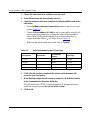
Steps to Configuring Operating System Settings ...........................................................3-1
Run CPCFG .............................................................................................................3-1
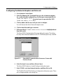
Configuring the Network Adapters and Protocols ....................................................3-3
Appendix A
Switch and Jumper Settings
Switch and Jumper Settings .......................................................................................... A-1

viii
303321-A Rev. 00
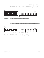
TX-2000 Card .......................................................................................................... A-1
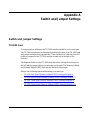
TX-2000 First Span (Memory Address D0000, Interrupt Request 5) ............... A-2
TX-2000 Second Span (Memory Address D2000, Interrupt Request 7) .......... A-2
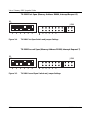
TX-2000 Third Span (Memory Address D4000, Interrupt Request 9) .............. A-3
TX-2000 Fourth Span (Memory Address D6000, Interrupt Request 11) .......... A-3
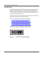
AG-T1/E1 Card ....................................................................................................... A-4
AG-T1/E1 First Span (Base Memory Address 02C0) ....................................... A-4
AG-T1/E1 Second Span (Base Memory Address 22C0) .................................. A-5
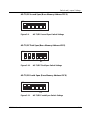
AG-T1/E1 Third Span (Base Memory Address 42C0) ......................................A-5
AG-T1/E1 Fourth Span (Base Memory Address 62C0) ................................... A-5

303321-A Rev. 00
ix
Figures
Figure 1-1. Top View of Inside of Voice Gateway with Cover Removed .....................1-1
Figure 1-2. AG-T1/E1 Card and TX-2000 Card ..........................................................1-2
Figure 1-3. 1-Span Voice Gateway Configuration ......................................................1-3
Figure 1-4. 2-Span Voice Gateway Configuration ......................................................1-4
Figure 1-5. 3-Span Voice Gateway Configuration ......................................................1-5
Figure 1-6. 4-Span Voice Gateway Configuration ......................................................1-6
Figure 2-1. MVIP Bus Cable .......................................................................................2-3
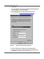
Figure 3-1. Select NMS Communications Processor Screen .....................................3-1
Figure 3-2. Select NMS Communications Processor Screen with Previous Board ....3-3
Figure 3-3. Microsoft TCP/IP Properties Dialog Box ..................................................3-4
Figure 3-4. TX-2000 First Span Switch and Jumper Settings ................................... A-2
Figure 3-5. TX-2000 Second Span Switch and Jumper Settings .............................. A-2
Figure 3-6. TX-2000 Third Span Switch and Jumper Settings .................................. A-3
Figure 3-7. TX-2000 Fourth Span Switch and Jumper Settings ................................ A-3
Figure 3-8. AG-T1/E1 First Span Switch Settings ..................................................... A-4
Figure 3-9. AG-T1/E1 Second Span Switch Settings ................................................ A-5
Figure 3-10. AG-T1/E1 Third Span Switch Settings .................................................... A-5
Figure 3-11. AG-T1/E1 Fourth Span Switch Settings ..................................................A-5


303321-A Rev. 00
xi
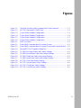
About This Guide
If you are responsible for upgrading your Voice Gateway 4000 chassis, you need
to read this guide.
Before You Begin
Be sure to complete the
NetSpeak License Upgrade Registration
card that you
received with your Upgrade package and fax it to the number listed on the card.
Once you complete and fax the form, you will receive the corresponding
registration file by e-mail.
If you want to Go to
Obtain preliminary upgrade information on card types and the upgrade
process in general
Chapter 1
Learn how to install the cards and install the MVIP bus cable Chapter 2
Obtain instructions for configuring the gateway software Chapter 3
Learn how to set the switches and jumpers for the cards Appendix A
Note:
You will not be able to complete the installation without the registration
file.
Caution:
Once you receive the registration file by e-mail, copy it to your
c:\NetSpeak\config
directory.

Voice Gateway 4000 Upgrade Guide
xii
303321-A Rev. 00
For information on proper operating environment requirements, refer to your
Voice Gateway 4000 Hardware Manual
.
Conventions
bold text
Indicates text that you need to enter in menu paths and
fields, as well as indicates the names of buttons, tabs,
check boxes, menu commands, and keyboard functions
which should be selected or pressed.
Example: Enter
NSINST
on the command line.
Example: Use the
dinfo
command.
Example: Click on the
Next
button.
Example: Enter a new user name in the
Database User
Name
field.
Example: Click on the
Database
tab.
Example: Select the
Use Defaults
check box.
Example:
1. Choose
New
from the
File
menu.
Example: Press the
Alt
key.
italic text
Indicates variable values in command syntax
descriptions, new terms, file and directory names, and
book titles.
quotation marks (“ ”) Indicates the title of a chapter or section within a book.
screen text
Indicates data that appears on the screen.
Example:
,,,Friendly/Fred, fred,
fred@acme.com,199.999.9.99,,,

About This Guide
303321-A Rev. 00
xiii
Bay Networks Technical Publications
You can now print technical manuals and release notes free, directly from the
Internet. Go to
support.baynetworks.com/library/tpubs
. Find the Bay Networks
products for which you need documentation. Then locate the specific category and
model or version for your hardware or software product. Using Adobe Acrobat
Reader, you can open the manuals and release notes, search for the sections you
need, and print them on most standard printers. You can download Acrobat
Reader free from the Adobe Systems Web site,
www.adobe.com
.
Documentation sets and CDs are available through your local Bay Networks sales
office or account representative.
Bay Networks Customer Service
You can purchase a support contract from your Bay Networks distributor or
authorized reseller, or directly from Bay Networks Services. For information or to
purchase a Bay Networks service contract, either call your local Bay Networks
field sales office or one of the following numbers:
Information about customer service is also available on the World Wide Web at
support.baynetworks.com
.
Region Telephone number Fax number
United States and
Canada
800-2LANWAN; then enter Express Routing
Code (ERC) 322, when prompted, to
purchase or renew a service contract
978-916-8880 (direct)
978-916-3514
Europe 33-4-92-96-69-66 33-4-92-96-69-96
Asia/Pacific 61-2-9927-8888 61-2-9927-8899
Latin America 561-988-7661 561-988-7550

Voice Gateway 4000 Upgrade Guide
xiv
303321-A Rev. 00
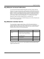
How to Get Help
If you purchased a service contract for your Bay Networks product from a
distributor or authorized reseller, contact the technical support staff for that
distributor or reseller for assistance.
If you purchased a Bay Networks service program, call one of the following Bay
Networks Technical Solutions Centers:
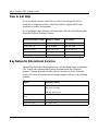
Bay Networks Educational Services
Through Bay Networks Educational Services, you can attend classes and purchase
CDs, videos, and computer-based training programs about Bay Networks
products. Training programs can take place at your site or at a Bay Networks
location. For more information about training programs, call one of the following
numbers:
Technical Solutions Center Telephone number Fax number
Billerica, MA 800-2LANWAN 978-916-3514
Santa Clara, CA 800-2LANWAN 408-495-1188
Valbonne, France 33-4-92-96-69-68 33-4-92-96-69-98
Sydney, Australia 61-2-9927-8800 61-2-9927-8811
Tokyo, Japan 81-3-5402-0180 81-3-5402-0173
Region Telephone number
United States and Canada 800-2LANWAN; then enter Express Routing Code (ERC)
282 when prompted
978-916-3460 (direct)
Europe, Middle East, and
Africa
33-4-92-96-15-83
Asia/Pacific 61-2-9927-8822
Tokyo and Japan 81-3-5402-7041

303321-A Rev. 00
1-1
Chapter 1
Chassis, Card Types, and Upgrade Overview
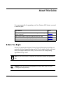
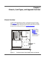
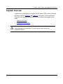
Chassis Overview
In order to begin upgrading your chassis, it is important to review the chassis
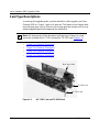
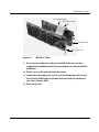
itself. Figure 1-1 shows a top-down view of the inside of the chassis, including
where the power supply, drive bay, and card slots are located. Be sure to review
this figure before starting with the section Card Type Descriptions
.
Figure 1-1. Top View of Inside of Voice Gateway with Cover Removed
Drive Bay
Power
Supply
Card Slots: See
Figure 1-3
(1-span),
Figure 1-4
(2-span),
Figure 1-5
(3-span),
and Figure 1-6
(4-span) for more
information on specific
card slot locations.

Voice Gateway 4000 Upgrade Guide
1-2
303321-A Rev. 00
Card Type Descriptions
In receiving this upgrade packet, you have decided to either upgrade your Voice
Gateway 4000 to a 2-span, 3-span, or 4-span unit. The figures in this chapter show
how each span type is set up. Review your current span type setup as well as your
planned upgrade span
before
beginning the installation.
• 1-Span Voice Gateway Description
• 2-Span Voice Gateway Description
• 3-Span Voice Gateway Description
• 4-Span Voice Gateway Description
Figure 1-2. AG-T1/E1 Card and TX-2000 Card
Note:
For the purposes of this document, each span type is known as a card
pair which includes the AG-T1/E1 card and the TX-2000 card (Figure 1-2).
MVIP Bus Cable
TX-2000 card
AG-T1/E1 card

Chassis, Card Types, and Upgrade Overview
303321-A Rev. 00
1-3
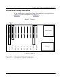
1-Span Voice Gateway Description
If you currently have a 1-span Voice Gateway, its card pair is set up as follows in
Figure 1-3. For more information, see Figure 1-1.
Figure 1-3. 1-Span Voice Gateway Configuration
AG-T1/E1
TX-2000
Empty
Empty
Empty
Empty
Empty
Empty
Processor
End Plate
Power Supply
Drive Bay
Front of Chassis
Back of Chassis
Span 1

Voice Gateway 4000 Upgrade Guide
1-4
303321-A Rev. 00
2-Span Voice Gateway Description
The 2-span Voice Gateway has two card pairs and is set up as follows in
Figure 1-4. For more information, see Figure 1-1.
Figure 1-4. 2-Span Voice Gateway Configuration
AG-T1/E1
TX-2000
Empty
Empty
Empty
Empty
Processor
End Plate
TX-2000
Power Supply
Drive Bay
Front of Chassis
Back of Chassis
Span 1 Span 2
AG-T1/E1

Chassis, Card Types, and Upgrade Overview
303321-A Rev. 00
1-5
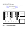
3-Span Voice Gateway Description
The 3-span Voice Gateway has three card pairs and is set up as follows in
Figure 1-5. For more information, see Figure 1-1.
Figure 1-5. 3-Span Voice Gateway Configuration
AG-T1/E1
TX-2000
Empty
Processor
End Plate
TX-2000
Empty
TX-2000
Power Supply
Drive Bay
Front of Chassis
Back of Chassis
Span 1 Span 2 Span 3
AG-T1/E1
AG-T1/E1

Voice Gateway 4000 Upgrade Guide
1-6
303321-A Rev. 00
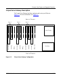
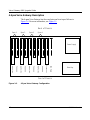
4-Span Voice Gateway Description
The 4-span Voice Gateway has four card pairs and is set up as follows in
Figure 1-6. For more information, see Figure 1-1.
Figure 1-6. 4-Span Voice Gateway Configuration
AG-T1/E1
TX-2000
Processor
End Plate
TX-2000
TX-2000
TX-2000
Power Supply
Drive Bay
Front of Chassis
Back of Chassis
Span 1 Span 2 Span 3 Span 4
AG-T1/E1
AG-T1/E1
AG-T1/E1
La page charge ...
La page charge ...
La page charge ...
La page charge ...
La page charge ...
La page charge ...
La page charge ...
La page charge ...
La page charge ...
La page charge ...
La page charge ...
La page charge ...
La page charge ...
La page charge ...
La page charge ...
La page charge ...
La page charge ...
La page charge ...
-
 1
1
-
 2
2
-
 3
3
-
 4
4
-
 5
5
-
 6
6
-
 7
7
-
 8
8
-
 9
9
-
 10
10
-
 11
11
-
 12
12
-
 13
13
-
 14
14
-
 15
15
-
 16
16
-
 17
17
-
 18
18
-
 19
19
-
 20
20
-
 21
21
-
 22
22
-
 23
23
-
 24
24
-
 25
25
-
 26
26
-
 27
27
-
 28
28
-
 29
29
-
 30
30
-
 31
31
-
 32
32
-
 33
33
-
 34
34
-
 35
35
-
 36
36
-
 37
37
-
 38
38


Bay Networks 4000 Upgrade Manual
- Taper
- Upgrade Manual
- Ce manuel convient également à
dans d''autres langues
- English: Bay Networks 4000
Autres documents
-
Nortel Networks Switch 4000 Manuel utilisateur
-
Gateway MT6709h Guide de référence
-
Gateway M-6829b Guide de référence
-
-
Gateway AJ6A Guide de référence
-
-
Gateway NV5356u Guide de référence
-
red lion RAM-99x1 Series Manuel utilisateur
-
Gateway MT6828 Guide de référence
-