Airwell PAC BT Series Guide d'installation
- Catégorie
- Climatiseurs split-system
- Taper
- Guide d'installation

Installation and operating manual
PAC BT
5 kW to 17 kW
M0GC6UN16-02
Nov.2016
English version


2
Dear Customer,
Congratulations on your purchase of the PAC BT, the air conditioning sy-
stem at annual cycle that offers the possibility in a sole system of meeting
all the heating, conditioning and domestic hot water needs.
Airwell is being working for years to offer systems able to assure the maxi-
mum comfort for long time with high reliability, efficiency , quality and safe-
ty. The target of the company is to offer advanced systems, that assure the
best comfort, reduce the energy consumption, the installation and mainte-
nance costs for all the life-cycle of the system.
With this manual, we want to give you information that are useful in all the
phases: from the reception, to the installation and use until the disposal so
that a system so advanced offers the best procedure of installation and use.
Best regards and have a nice reading !
AIRWELL RESIDENTIAL


3
Before any operation carefully read the GENERAL WARNINGS at the end of the manual
1
2
3
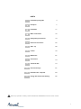
INDEX
Installation quick guide
4
Reception
7
Installation
11
Water connections
15
Refrigerating connections
19
Electrical connections
22
Start - up
28
Control
34
Maintenace
67
Accessories
73
Technical data
74
General warnings
81
Residual risks / Disposal
83
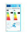
Energy data sheets and labelling
85
4
5
6
7
8
9
10
11
12
13

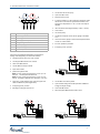
DHW
pump
No recircu-
lation pump
Power supply 230 or 430
Separate power supply and signal
!
Thermostat
Elfocontrol
2
(option)
Segnals
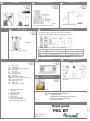
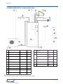
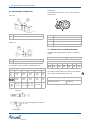
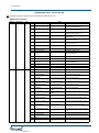
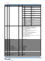
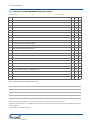
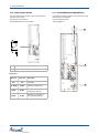
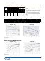
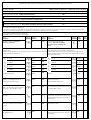
Size 5kW 7kW 9kW 12kW 14kW 17kW
Liquid Ø Outdoor 3/8” 3/8” 3/8” 3/8” 1/2” 1/2”
Gas Ø Outdoor 3/8” 1/2” 1/2” 5/8” 5/8” 3/4”
Size 5kW 7kW 9kW 12kW 14kW 17kW
Min. content / Liters 17 20 25 33 40 50
System
pump
Anti-vibration joints
Cut-off valves
Vent
KPa = Useful pump discharge head
* Storage tank: this is present when the radiator circuit is excluded and there is not enough water
in the towel warmer circuit
*
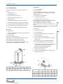
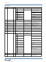
Respect the functional clearances for maintenance
Size L2 W1
5 kW - 9 kW 200 250
12 kW -
14kW
250 300
17kW 300 350
Check that the pump head is adequate to the type of system
On the RS485
board is possible
to connect only
one con-
trol,RCW15
keypad
!
Avoid installations next to bedrooms
Install in a local or compartment where the
temperature can't drop below 0 ° C.
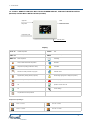
For details see the manual sections
Indoor unit
Place so that it doesn't disturb
Outdoor unit
Water minimum content always circulating
L
Pump head/pressure drops of the system
M
Functional clearances/access
B
Refrigerant piping: distance maximum height differences
G
Water connections
N
Electrical connections
F
Consider sound emissions
A

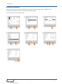
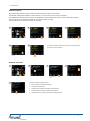
Rapid guide
PAC BT
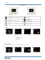
BEFORE REQUESTING START-UP
Completed system
Refrigeration circuit emptying and charging
Water circuit loading and venting
Electrical connections
!
Reference document
M0GC6UN16
Provide a protection
< 15 °f. ?
If necessary, install water softener
To avoid the water freezing downstream of the
drain, lay the tube below the frost line (A).
Provide windbreaks or similar
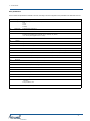
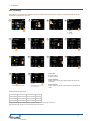
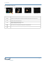
1 Domestic Hot Water output
2 Water input
3 System water return
4 System water outlet
5 Pipe line( liquid )
6 Pipe line ( gas)
8 Solar system input (option)
9 Solar system output (option)
10 Domestic Hot Water recirculation
Litres ? °C ?
Tmax 95 °C
Charge OK ?
Carefully wash the system
Sizing expansion tanks according to the sy-
stem features
Condensate discharge
D
Strong winds
E
Snowdrifts
C
Water features
H
Domestic Hot Water Requirements
I
Indoor unit drains
O
Expansion tanks
P
System cleaning
Q
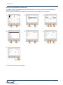
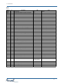
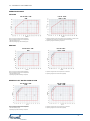
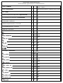
The requirements vary by the number of people living in the building
Estimated average daily per capita consumption of hot water
Requirements Liters - day - people (bathroom) Liters - day - people (kitchen)
Low Min.15 > max. 30 Min. 10 > max. 20
Medium Min.30 > max. 60 Min. 20 > max. 40
High Min.60 > max. 120 Min. 40 > max. 80
Example: average requirement for 4 people need about 230 litres/day
* Possibility of adding auxiliary cylinder in case of high hot water request
A System valve
I.A. Aqueduct input
C.C. Components provided by Customer
DEF Dirt separator
F Water filter
M Pressure gauge
P. A. Descaler protection
PS Solar pump
RID Pressure reducing valve
VEACS Domestic hot water expansion tank
VEI System expansion tank
VES Solar expansion tank
VR Check valve
VT Mixing valve thermostatic
MTGC40E16-01 26-05-16

6
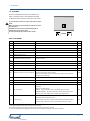
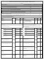
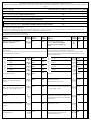
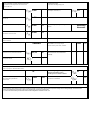
GENERAL
Serie
Size
Serial number
Year of manufacture
Wiring diagram
UNIT INDENTIFICATION
Operate in compliance with safety regulations in force .
Use single protection devices.
PRELIMINARY INFORMATION
Before beginning the work, ensure you that have the final
project for installing the system and positioning the units.
Recommended instruments
Set of Philips and flathead screwdrivers;
Cutters;
Drill;
Scissors;
Set of open spanners or pipe wrenches;
Range;
Hydraulic material for the sealing of the threads;
Electrical equipment for the connections;
Cut prevention gloves;
Tester and amperometric pliers.
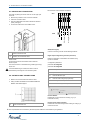
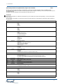
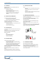
Serial number label
The serial number label is positioned on the unit and allows to
indentify all the unit features.
It has not to be removed for any reason.
It reports the regulations indications such as:
Machine type, exmple:
Series —> PAC BT
Size —> 5kW,7kW,…..17kW
Serial number
12 characters Axxxxxxxxxxx
Year of manufacture
Wiring diagram number
Electrical data
Supplier logo and address .
Serial number
It identifies uniquely each machine.
It identifies specific spare parts for the machine.
Assistance request
Note data from the serial number label and write them in the
chart on side, so you will find them easily when needed.
In case of intervention you have to provide data.

7
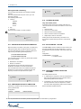
1 - ENERGY DATA SHEETS AND LABELLING
1.1 - DELIVERY CONTROL
1.2 - STORAGE
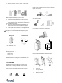
1.3 - HANDLING
?
A
A
Before handling verify that the unit keeps its balance.
B
Indoor unit
C
Fork input side the
D
Belt input side for lifting by crane
E
Maximum inclination
A identification label
A
Indoor unit
Outdoor unit
Before accepting the delivery you have to check:
that the unit hasn’t been damaged during transport.
Check that the materials delivered correspond with that
indicated on the transport document comparing the data
with the identification label ‘A’ positioned on the packaging.
In case of damage or anomaly:
Write down on the transport document the damage you
found and quote this sentence: "Conditional acceptance
clear evidence of deficiencies/damages during transport".
Contact supplier and the carrier by fax and registered mail
with advice of receipt.
Any disputes must be made within the 8 days following the
delivery. Complaints after this period are invalid.
Shelter from: direct sunlight, rain, sand and wind.
Stocking temperature:
maximum 50°C
minimum -10°C
The respect of the instructions on the exterior side of the
packaging assures the physical and functional integrity of the
unit for the final user’s advantage.
Verify unit weight and handling equipment lifting capacity .
The following examples are indications the choice of the
means and of the handling modes will depend on factors.
Use protection (A) to avoid the unit damaging
Identify critical points during handling (disconnected routes,
flights, steps, doors).
Stair climbing trolley.

8
1 - RECEPTION
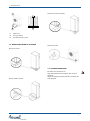
1.4 - REMOVE WOODEN PLATFORMS
F
Outdoor unit
G
Fork input side the
H
Input side for lifting by crane
G H
F
Be careful not to damage the unit.
Keep packing material out of children's reach it may be
dangerous.
Recycle and dispose of packing material in conformity with
local regulations.
1.5 - PACKING REMOVING
Remove the screws
Remove planks and mural
Remove the screws by brackets
Remove the screws

9
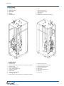
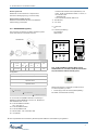
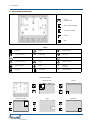
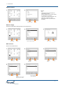
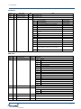
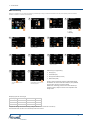
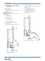
GENERAL
H. Vent
I. Solar system input (option)
J. Solar system output (option)
K. Aqueduct input
L. DHW output
M. Domestic hot water recirculation input (DHW )
CONNECTIONS
COMPONENTS
A
1
B
C
D
E
2
3
8
7
6
5
4
11
13
14
17
18
16
15
11. Electronic expansion valve
12. Solar probe (Provided by the customer)
13. System inlet temperature probe
14. Safety valve system DHW
15. System pump
16. DHW / System production valve
17. DHW pump
18. Electric panel
G
12
H I
J
K
F
L
M
9
1. Resistance (2kW)
2. System expansion vessel connection ø1/2” (Provided by the customer)
3. System exchanger
4. Differential pressure switch
5. System outlet temperature probe
6. Safety valve system side
7. DHW exchanger
8. Solar DHW exchanger (option)
9. Solar temperature probe
10. System expansion vessel connection ø1/2” (Provided by the customer)
10
A. Boiler return (option)
B. Boiler supply (option)
C. System return
D. System outlet
E. Gas line
F. Liquid line
G. Electronic Anode

10
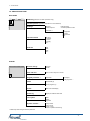
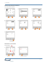
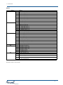
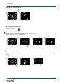
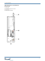
GENERAL
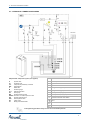
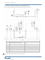
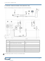
SCHEME CONNECTIONS
On the RS485 board is possible to connect only one control, RCW15 keypad
!
2
1
3
4
5
9
6
7.2
3.1
3.2
7.1
11
10
1
7
1
Supply line Pag.22
7.1
Power supply unit 12Vdc
(option)
System Pag.15
7.2
RS485
System outlet Ø 1”1/4M
DHW drain valve
Provided by the
customer
Pag.16
8
2
System return Ø 1”1/4M
System drain valve
Provided by the
customer
Pag.16
3
Solar panels (option) Ø 3/4”M Pag.18
9
Ethernet max 30 m UTP cat. 5 Pag.22
3.1
Solar panels unit (not provided)
10
Pipe liness
Provided by the
customer
Pag.19
3.2
Solar pump (not provided)
11
Unit drain
Provided by the
customer
Pag.13
4
Acqueduct Ø 1/2”M Pag.15
5
DHW Ø 1/2”M Pag.15
6
Room thermostat (not sup- Pag. 22
7
RCW15 control (option)
8
!
RCW15

11
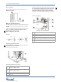
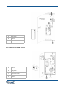
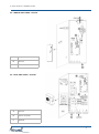
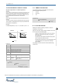
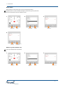
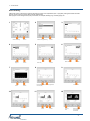
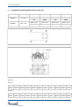
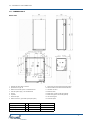
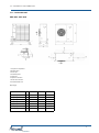
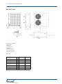
2 - INSTALLATION
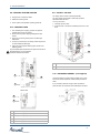
Outdoor unit
2.1 - CLEARANCES
H1 H L1 L W1 W W2 L2
200 2040 800 800 30 600 100 10
Size H L L2 W1 W W2
5kW - 9kW 988 450 200 250 942 600
12 kW - 14kW 1234 460 250 300 1087 600
17kW 1137 720 350 350 1738 600
Install OUTDOOR
in fixed positions
If the unit is installed on a roof or terrace, check the load
capacity and the possibility for discharging the condensate.
Installation standards:
spaces for the air intake/exhaust
condensate water draining
install the unit raised from the ground
Prefer places where the unit doesn't disturb the neighbours.
Avoid installations in places subject to flooding
Avoid installations next to bedrooms or windows.
Avoid snow accumulating obstructing for air ejection and
suction
A correct circulation of the air is indispensible to guarantee the
good working order of the machine.
Avoid therefore:
obstacles to the airflow;
exchange difficulties;
leaves or other foreign bodies that can obstruct the
exchange batteries;
winds that hinder or favour the airflow;
heat or pollution sources close to the unit (chimneys,
extractors etc);
stratification (cold air that stagnates at the bottom);
recirculation (expelled air that is sucked in again);
positioning below the level of the threshold, close to very
high walls, attics or in angles that could give rise to
stratification or recirculation phenomenons.
Ignoring the previous indications could:
energy efficiency decrease;
blocks due to HIGH PRESSURE (in summer) or LOW
PRESSURE (in winter).
Choose the installation place according to the following
criteria:
customer approval
safe accessible position
carry out maintenance operations
technical spaces requested by the unit
water connections
max. distance allowed by the electrical connections
max. distance allowed by the refrigeranting connections
control points with capacity adequate to the unit weight
verify that all bearing points are aligned and leveled
sound levels (TECHNICAL INFORMATION section)
Indoor unit
installed inside
in a dry room/compartment where the temperature cannot
fall below 0 degrees
in fixed positions
Keep to the indicated safety spaces.
Prefer places where the unit doesn't disturb the neighbours.
Avoid installations in places subject to flooding
Avoid installations next to bedrooms or windows.
The spaces can be occupied by objects that must be easily
removeable in case of maintenance interventions.

12
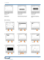
2 - INSTALLATION
Avoid installations next to bedrooms or windows.
Consider sound emissions
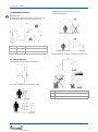
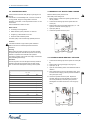
2.2- MAXIMUM DISTANCE
Refrigerant pipes:
in vertical sections ensure the presence of siphons every six
metres of unevenness (on the supply/suction line only).
A max 25 m equivalent length of the pipe lines
B max 15 m height difference
C 6 m 6 m back up → siphon (gas line)
2.3 - OUTDOOR UNIT
Keep the min. distances from the podestrian areas.
Consider clearances and direction of expelled air.
Provide windbreaks (or similar) in locations with strong winds.
A Provide a protection.
B Avoid snow accumulations on batteries.
C Install the unit lifted from the ground.

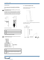
13
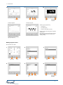
2 - INSTALLATION
D Condensate discharge connection Ø 13
E Frost line
F
Layer of gravel or pebbles to help with condensate
drainage
To avoid freezing of the water downstream of the drain lay the
tube below the frost line (E).
Position the indoor unit on a flat, level surface.
Install the feet supplied (A)
2.4 - LEVELLING INDOOR UNIT
Condensate discharge via drainage
Use a spanner (36mm) to adjust the support feet and level the
position of the indoor unit.
When a heat pump is running it produces a considerable
amount of water due to the defrosting cycles of the outdoor
coil.
The condensation must be eliminated in a manner to avoid
wetting pedestrian areas.
With extensive very cold outdoor temperatures, condensation
could freeze outside the unit blocking the flow and causing a
slow build-up of ice; therefore special attention must be paid
to eliminating condensation, raising the unit off the ground and
evaluating whether antifreeze elements should be installed.
Condensate drain
A Condensate collection basin
B Unit support
C Condensate discharge connection
Customer care accessories

14
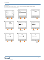
2 - INSTALLATION
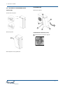
2.5 - ACCESS TO THE INDOOR PARTS
A
A
A
A
A
INDOOR UNIT
B
B
Same sequence for the opposite side.
Unhook latch of the panel
Remove the panel
OUTDOOR UNIT
Remove the screws A
COMPONENTS SUPPLIED (indoor)
Refrigerating line connections: page 20

15
3 - WATER CONNECTIONS
3.1 - HYDRAULIC CONNECTION SCHEMA
In the tightening operations always use the wrench and backup wrench.
Indispensabile components system (not supplied)
A System valve
I.A. Aqueduct input
C.C. Components provided by Customer
DEF Dirt separator
F Water filter
M Pressure gauge
P. A. Descaler protection
PS Solar pump
RID Pressure reducing valve
VEACS Domestic hot water expansion tank
VEI System expansion tank
VES Solar expansion tank
VR Check valve
VT Mixing valve thermostatic
1 Domestic Hot Water output
2
Water input
3
System water return
4
System water outlet
5
Refrigerant line( liquid )
6
Refrigerant line ( gas)
8
Solar system input (option)
9
Solar system output (option)
10 Domestic Hot Water recirculation
Vent
Cut-off valves
Anti-vibration joints
PAC BT ODU

16
3 - WATER CONNECTIONS
A
system safety valve drain:
discharge in pressure (3 bar)
B
DHW safety valve drain:
discharge in pressure (6 bar)
drain accumulation / drain pit
C
H Boiler drain
A system safety valve
B
domestic hot water safety valve
D system draining tap
E domestic hot water draining tap
F system draining tap
G solar panel drain tap (domestic hot water)
Connecting the indoor unit drains
Any anti-freeze liquid contained in the system should not be
discharged freely as it is a pollutant.
It must be collected and reused.
An air bleed valve
Install the highest points of tubes in a way that the air can
escape form the circuit.
Inside the unit there are 2 water safety valves (the first one 6
bar on the Domestic Hot Water tank circuit, the second one 3
bar on the installation circuit) that must be connected to a
suitable drain, otherwise if valves intervened and flood the
rooms, the heat pump manufacturer will not be responsible.
The filter is extremely important: it helps to lockout any impuri-
ties in the water and avoid clogging the system and heat ex-
changer.
It must be installed immediately at the entrance to the water
mains, in a position that is easily accessible for cleaning.
The filter should never be re-moved.
Check for clogging from time to time
Installation
OK
Water filter (provided by the client)
A
D
B
F
E
For drain (see page 69)
G
Secure the pipes with hose clamps

17
3 - WATER CONNECTIONS
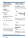
3.3 DOMESTIC HOT WATER TANK CHARGE
Maximum DWH system pressure 6 bar
DWH saftey valve setting 6 bar
1. Before charging, position the systems general switch in
the 'off' position .
2. Check that the draining taps of the system DWH are
closed ( C ).
3. Start the filling opening the water loading tap ( I.A. - see
hydraulic connection schema page 15)
4. Open taps (10-1-2)
5. Check the hydraulic seal of the joints.
3.4 SYSTEM CHARGE HEATING / COOLING
1. Check that the draining taps of the system are closed ( D-
F).
2. Start the filling opening the tap (A - see page 15)
3. Open taps (3 - 4)
4. Open all of the bleeding valves of the related terminals or
radiators
5. When water begins to exit from the bleeding valve, close
and continue the charging until the pressure intended for
the system (max.3 bar)
6. Check the hydraulic seal of the joints. Repeat the
operation after the unit has operated for a number of
hours and periodically control the system pressure.
Reintegration is carried out when the unit is off (pump
OFF).
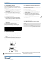
3.2 - WATER FEATURES
C
D
F
Water features
confirming to local regulations
Water hardness (CaCo
3
) between 10°f and 25°f
Langelier (I
L
) index between 0 and +0.4
within the limits indicated by table
The water quality must be checked by qualified personnel.
Hardness
If the water hardness is high install a system suitable to
preserve the unit from harmful deposits and limestone
formations.
Cleaning
Before making the water connections to unit clean carefully
the system with specific and effective products for removing
residues or impurities that could affect the operation.
The existing systems must be free from sludgs, contaminants
and protected against foulings.
Exclusions
The warranty does not cover damages caused by limestone
formations, deposits and impurities from the water supply
and / or failure from failed system clearing to clean system.
Water component for corrosion limit on Copper
PH 7,5 ÷ 9,0
SO
4
--
< 100 ppm
HCO
3
-
/ SO
4
--
> 1
Total Hardness 4,5 ÷ 8,5 dH
Cl- < 50 ppm
PO
4
3-
< 2,0 ppm
NH3 < 0,5 ppm
Free Chlorine < 0,5 ppm
Fe
3
+
< 0,5 ppm
Mn
++
< 0,05 ppm
CO
2
< 50 ppm
H
2
S < 50 ppb
Temperature < 65 °C
Oxygen content < 0,1 ppm
Fill the Domestic Hot Water tank (DHW) only during the unit
start-up.
If the house is not immediately lived ,or the unit is turned off
for long periods, empty the storage tank to avoid the
stagnation of the water, or with temperatures close to 0°C the
risk of freeze.
See the Maintenance section for drain

18
3 - WATER CONNECTIONS
3.5 - SOLAR PREDISPOSITION - OPTION
Solar probe
The solar panels are equipped with:
a control panel (provided by costumer)
a temperature probe (provided by costumer)
For their operating with solar panels:
place the temperature probe on well ‘E’ positioned on the
storage tank
carried out the electrical connections
the solar system must be enabled (see page 38).
A Solar system water inlet Ø 3/4"
B Solar system water outlet Ø 3/4"
C Solar pump (provided by the client)
D
Solar expansion tank the Ø 3/4" (provided by the
client)
E
Solar probe well
F Solar draining tap
Any anti-freeze liquid contained in the solar system should not
be discharged freely as it is a pollutant. It must be collected
and reused.
The solar panel turns on whenever the machine's solar sensor
temperature reading is greater than that of the storage tank by
at least 8°C.
The solar panel turns off when the storage tank temperature
has reached 85°C of the machine's solar sensor temperature
reading is lower than that of the storage tank.
E
F
La page charge ...
La page charge ...
La page charge ...
La page charge ...
La page charge ...
La page charge ...
La page charge ...
La page charge ...
La page charge ...
La page charge ...
La page charge ...
La page charge ...
La page charge ...
La page charge ...
La page charge ...
La page charge ...
La page charge ...
La page charge ...
La page charge ...
La page charge ...
La page charge ...
La page charge ...
La page charge ...
La page charge ...
La page charge ...
La page charge ...
La page charge ...
La page charge ...
La page charge ...
La page charge ...
La page charge ...
La page charge ...
La page charge ...
La page charge ...
La page charge ...
La page charge ...
La page charge ...
La page charge ...
La page charge ...
La page charge ...
La page charge ...
La page charge ...
La page charge ...
La page charge ...
La page charge ...
La page charge ...
La page charge ...
La page charge ...
La page charge ...
La page charge ...
La page charge ...
La page charge ...
La page charge ...
La page charge ...
La page charge ...
La page charge ...
La page charge ...
La page charge ...
La page charge ...
La page charge ...
La page charge ...
La page charge ...
La page charge ...
La page charge ...
La page charge ...
La page charge ...
La page charge ...
La page charge ...
La page charge ...
La page charge ...
La page charge ...
La page charge ...
La page charge ...
La page charge ...
La page charge ...
La page charge ...
La page charge ...
La page charge ...
La page charge ...
La page charge ...
La page charge ...
La page charge ...
La page charge ...
La page charge ...
La page charge ...
La page charge ...
La page charge ...
La page charge ...
La page charge ...
La page charge ...
La page charge ...
La page charge ...
-
 1
1
-
 2
2
-
 3
3
-
 4
4
-
 5
5
-
 6
6
-
 7
7
-
 8
8
-
 9
9
-
 10
10
-
 11
11
-
 12
12
-
 13
13
-
 14
14
-
 15
15
-
 16
16
-
 17
17
-
 18
18
-
 19
19
-
 20
20
-
 21
21
-
 22
22
-
 23
23
-
 24
24
-
 25
25
-
 26
26
-
 27
27
-
 28
28
-
 29
29
-
 30
30
-
 31
31
-
 32
32
-
 33
33
-
 34
34
-
 35
35
-
 36
36
-
 37
37
-
 38
38
-
 39
39
-
 40
40
-
 41
41
-
 42
42
-
 43
43
-
 44
44
-
 45
45
-
 46
46
-
 47
47
-
 48
48
-
 49
49
-
 50
50
-
 51
51
-
 52
52
-
 53
53
-
 54
54
-
 55
55
-
 56
56
-
 57
57
-
 58
58
-
 59
59
-
 60
60
-
 61
61
-
 62
62
-
 63
63
-
 64
64
-
 65
65
-
 66
66
-
 67
67
-
 68
68
-
 69
69
-
 70
70
-
 71
71
-
 72
72
-
 73
73
-
 74
74
-
 75
75
-
 76
76
-
 77
77
-
 78
78
-
 79
79
-
 80
80
-
 81
81
-
 82
82
-
 83
83
-
 84
84
-
 85
85
-
 86
86
-
 87
87
-
 88
88
-
 89
89
-
 90
90
-
 91
91
-
 92
92
-
 93
93
-
 94
94
-
 95
95
-
 96
96
-
 97
97
-
 98
98
-
 99
99
-
 100
100
-
 101
101
-
 102
102
-
 103
103
-
 104
104
-
 105
105
-
 106
106
-
 107
107
-
 108
108
-
 109
109
-
 110
110
-
 111
111
-
 112
112


Airwell PAC BT Series Guide d'installation
- Catégorie
- Climatiseurs split-system
- Taper
- Guide d'installation
dans d''autres langues
Documents connexes
Autres documents
-
Panasonic WHADC1216H6E5C Mode d'emploi
-
Daikin EBLQ036BA6VJU1 Guide d'installation
-
 Regency Fireplace Products E110 Le manuel du propriétaire
-
ACV Glass HP 300 (C) Manuel utilisateur
-
Gorenje TC100ZNT Le manuel du propriétaire
-
Dometic MCS6 Mode d'emploi
-
-
Stovax Radiance Inset Edge User Instructions
-
-
