Maytag MHN30PDAGW Guide d'installation
- Catégorie
- Machines à laver
- Taper
- Guide d'installation
Ce manuel convient également à

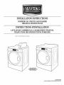
INSTALLATIONINSTRUCTIONS
COMMERCIALFRONT-LOADWASHER
ORIGINALINSTRUCTIONS
INSTRUCTIONSD'INSTALLATION
LAVE.LINGECOMMERCIALACHARGEMENTFRONTAL
TRAI)UCTIONDESINSTRUCTIONSD'ORIGINE
Table of Contents/Table des mati_res ........................................ 2
Model/ModUle
MHN30PDBGW and
MHN30PNBGW
WlO487509B
www.maytagcommercialaundry.com

TABLEOFCONTENTS
WASHER SAFETY ................................................................................... 2
WASHER DISPOSAL ............................................................................... 3
iNSTALLATiON REQUIREMENTS .......................................................... 4
Tools and Parts ..................................................................................... 4
Options ................................................................................................. 4
Location Requirements ........................................................................ 5
Drain System ........................................................................................ 5
Electrical Requirements ........................................................................ 6
INSTALLATION INSTRUCTIONS ............................................................ 7
Remove Transport System ................................................................... 7
Power Cord Installation ........................................................................ 7
Connect the Inlet Hoses ....................................................................... 8
Connect the Drain Hose ....................................................................... 8
Secure the Drain Hose ......................................................................... 9
Level the Washer .................................................................................. 9
Payment System Set-up .................................................................... 10
Installing Pad Strips ........................................................................... 10
Complete Installation .......................................................................... 10
USER & SET-UP INSTRUCTIONS ........................................................ 11
General User Information ................................................................... 11
Control Set-up Procedures ................................................................ 11
Set-up Codes ..................................................................................... 12
Washer Diagnostic Modes ................................................................. 15
WASHER CARE ..................................................................................... 16
Cleaning Your Washer ........................................................................ 16
Water Inlet Hoses ............................................................................... 16
ASSISTANCE OR SERVICE .................................................................. 17
Accessories ........................................................................................ 17
WARRANTY ........................................................................................... 17
DECLARTION OF CONFORMITY ......................................................... 18
TABLEDESMATIERES
SECURIT_: DU LAVE-LINGE ................................................................. 19
MISE AU REBUT DU LAVE-LINGE ...................................................... 20
EXIGENCES D'INSTALLATION ............................................................ 20
Outillage et pi_ces .............................................................................. 20
Options ............................................................................................... 21
Exigences d'emplacement ................................................................. 21
Syst_me de vidange ........................................................................... 22
Sp6cifications 61ectriques .................................................................. 22
INSTRUCTIONS D'INSTALLATION ...................................................... 23
D6pose du syst_me de transport ....................................................... 23
Installation du cordon d'alimentation ................................................. 23
Raccordement des tuyaux d'alimentation .......................................... 24
Raccordement du tuyau de vidange .................................................. 25
Immobilisation du tuyau de vidange .................................................. 25
R6glage de I'aplomb du lave-linge ..................................................... 26
Param6trage du syst_me de paiement .............................................. 26
Installation des bandes de protection ................................................ 26
Achever I'installation .......................................................................... 27
INSTRUCTIONS DE CONFIGURATION ............................................... 28
Informations g6n6rales pour I'utilisateur ............................................ 28
Proc6dures de r6glage des syst_mes de commande ........................ 28
Codes de param6trage ...................................................................... 29
Mode de diagnostic du lave-linge ...................................................... 32
ENTRETIEN DU LAVE-LINGE .............................................................. 34
Nettoyage du lave-linge .................................................................... 34
Tuyaux d'arriv6e d'eau ....................................................................... 35
ASSISTANCE OU SERVICE .................................................................. 35
Accessoires ........................................................................................ 35
GARANTIE .................................................................. Couverture arri_re
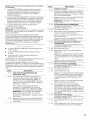
WASHERSAFETY
Your safety and the safety of others are very important.
We have provided many important safety messages in this manual and on your appliance. Always read and obey all safety
messages.
This is the safety alert symbol.
This symbol alerts you to potential hazards that can kill or hurt you and others.
All safety messages will follow the safety alert symbol and either the word "DANGER" or "WARNING."
These words mean:
You can be killed or seriously injured if you don't immediately
follow instructions.
You can be killed or seriously injured if you don't follow
instructions.
All safety messages will tell you what the potential hazard is, tell you how to reduce the chance of injury, and tell you what can
happen if the instructions are not followed.
2

iMPORTANT SAFETY iNSTRUCTiONS
WARNING: To reduce the risk of fire, electric shock, or injury to persons when using the washer, follow basic precautions,
including the following:
m=Under certain conditions, hydrogen gas may be
produced in a hot water system that has not been used
for 2 weeks or more. HYDROGEN GAS IS
EXPLOSIVE. If the hot water system has not been
used for such a period, before using the washing
machine, turn on all hot water faucets and let the water
flow from each for several minutes. This will release
any accumulated hydrogen gas. As the gas is
flammable, do not smoke or use an open flame during
this time.
[] Before the washer is removed from service or discarded,
remove the door or lid.
[] Do not install or store the washer where it will be exposed to
the weather.
[] Do not repair or replace any part of the washer or attempt any
servicing unless specifically recommended in this manual or in
published user-repair instructions that you understand and
have the skills to carry out.
[] See "Electrical Requirements" for earthing instructions.
SAVE THESEINSTRUCTIONS
WASHERDISPOSAL
This appliance is marked according to the European directive 2002/96/EC on Waste Electrical and Electronic Equipment
(WEEE).
By ensuring this product is disposed of correctly, you will help avoid potential negative consequences for the environment and
human health, which could otherwise be caused by inappropriate waste handling of this product.
The symbol on the product, or on the documents accompanying the product, indicates that this appliance may not be treated
as household waste. Instead it shall be handed over to the applicable collection point for the recycling of electrical and
electronic equipment.
Disposal must be carried out in accordance with local environmental regulations for waste disposal.
For more detailed information about treatment, recovery and recycling of this product, please contact your local city office, your
household waste disposal service or the shop where you purchased the product.
Model Nornenclature
MHN - Maytag
30 - Model Type Number
PN - Electronic Control - Non-Pay
PD - Electronic Control - Coin Drop enabled
3

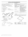
INSTALLATIONREQUIREMENTS
Gather the required tools and parts before starting installation.
The parts supplied are in the washer drum.
Tools needed for connecting the water inlet hoses
[] Pliers (that open to [] Flashlight (optional)
39.5 mm [1%6"])
Tools needed for installation
[] Open end wrenches [] Level
1/2" and 9/16"
[] Wood block
[] Torx®l- T-20 Security [] Ruler or measuring tape
screwdriver
[] 1/4" nut driver
Parts supplied
Alternate Parts
Your installation may require additional parts. Ifyou are interested
in purchasing one of the items listed here, contact your
authorized Maytag distributor.
t t _t
If you have You will need to buy
Laundry tub or standpipe Sump pump system (if not already
taller than 2.4 m (96") available)
Overhead sewer
Standard 76 L (20 gal.), 762 mm
(30") tall drain tub or utility sink and
sump pump (available from local
plumbing suppliers)
Floor drain
Siphon break, Part Number
285834; additional drain hose,
Part Number 8318155; and
connector kit, Part Number 285835
Drain hose too short 1.2 m (4 ft) drain hose extension
kit, Part Number 285863
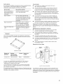
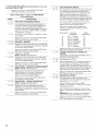
D
c
G
E
A. U-shaped hose form
B. Water inlet hoses (2)
C. Inlet hose washers (4)
D. Transit bolt hole plug (4)
Parts supplied for PD Models:
E. Removable tie strap
F. Drain hose
G. Hose clamp
Pedestal
You have the option of purchasing pedestals separately for this
washer. The pedestal will add to the total height of the washer.
Optionalpedestal
Pedestal Approximate Color
Height height with washer
73 mm (2%") 1207 mm (47.5") White
Part Number
WHP0400VW
Service door lock cam
Foam pads
1® TORX isa registered trademark of Saturn Fasteners, Inc.
4

3!¸,0 czii!/i;i 0s i!!ii_0qil_;_i!iliii_i¸_ii!!_s_:iii_ii!!_ii:i_;i_iii;5
Selecting the proper location for your washer improves
performance and minimizes noise and possible washer "walk."
Your washer can be installed under a custom counter, or in a
basement, laundry room, or recessed area. See "Drain System."
Companion appliance location requirements should also be
considered. Proper installation is your responsibility.
You will need
[] A water heater set to deliver 49°C (120°F) water to the
washer.
[] A grounded electrical outlet located within 1.8 m (6 ft.) of
where the power cord is attached to the back of the washer.
See "Electrical Requirements."
[] Hot and cold water taps located within 1.2 m (4 ft.) of
the hot and cold water fill valves, and water pressure of
137.9-689.6 kPa (20-100 psi).
[] A level floor with a maximum slope of 25 mm (1") under entire
washer. Installing the washer on soft floor surfaces, such as
carpets or surfaces with foam backing, is not recommended.
[] A sturdy and solid floor to support the washer with a total
weight (water and load) of 180 kg (400 Ibs).
Do not operate your washer in temperatures below 0°C (32°F).
Some water can remain in the washer and can cause damage
in low temperatures.
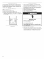
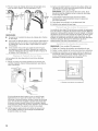
Installation clearances
[] The location must be large enough to allow the washer
door to be fully opened.
[] Additional spacing should be considered for ease of
installation and servicing. The door opens more than 90°,
and it is not reversible.
[] Additional clearances might be required for wall, door, and
floor moldings.
[] Additional spacing of 1" (25 mm) on all sides of the washer
is recommended to reduce noise transfer.
[]
Companion appliance spacing should also be considered.
Washer Dimensions
1282 mm
686 mm
1134 mrn
(44%")
_ (28,3/,0}
Door is not reversible
A floor drain should be provided under the bulkhead.
Prefabricated bulkheads with electrical outlets, water inlet
lines, and drain facilities should be used only where local
codes permit.
The washer can be installed using the standpipe drain system
(floor or wall), the laundry tub drain system, or the floor drain
system. Select the drain hose installation method you need.
See "Tools and Parts."
Standpipe drain system - wall or floor (views A & B)
The standpipe drain requires a minimum diameter standpipe of
50 mm (2"). The minimum carry-away capacity can be no less
than 45.5 L (12 gal.) per minute, per washer.
The top of the standpipe must be at least 762 mm (30") high and
no higher than 2.4 m (96") from the bottom of the washer.
A B
Laundry tub drain system (view C)
The laundry tub needs a minimum 76 L (20 gal.) capacity. The top
of the laundry tub must be at least 762 mm (30") above the floor.
Floor drain system (view D)
The floor drain system requires a siphon break that may be
purchased separately. See "Tools and Parts."
The siphon break must be a minimum of 710 mm (28") from the
bottom of the washer. Additional hoses might be needed.
__ 71o_
C D
5

Dangerous Voltage
Electric Shock Hazard
Plug into an earthed socket outlet.
Do not use an adapter.
Do not use an extension cord.
Failure to follow these instructions can result in death,
fire, or electric shock.
EARTHING iNSTRUCTiONS
This washer must be earthed. In the event of a malfunction
or breakdown, earthing will reduce the risk of electric
shock by providing a path of least resistance for electric
current. This washer is equipped with a cord having an
equipment-earthing conductor and an earthing plug. The
plug must be plugged into an appropriate outlet that is
properly installed and earthed in accordance with all local
codes and ordinances.
WARNING: Improper connection of the equipment-
earthing conductor can result in a risk of electric shock.
Check with a qualified electrician or serviceman if you are in
doubt as to whether the appliance is properly earthed.
Do not modify the plug provided with the appliance - if it will
not fit the outlet, have a proper outlet installed by a qualified
electrician.
NOTE: Electrical safety standards: The manufacturer has
chosen compliance with EC/EN.60335 standards as the most
appropriate for this product.
[] Sound Pressure Level, Lpa: 58 dbA (uncertainty,
Kpa: +/-3.6 dbA)
[] A 220-240V, 50 Hz., fused electrical supply is required. A
time-delay 10-16A fuse or circuit breaker is recommended.
[] This washer is equipped with a power supply cord having
a 3 prong earthed plug.
[] To minimize possible shock hazard, the cord must be
plugged into a mating, 3 prong, grounding-type outlet,
grounded in accordance with local codes and ordinances.
If a mating outlet is not available, it is the personal
responsibility and obligation of the customer to have the
properly grounded outlet installed by a qualified electrician.
[] If codes permit and a separate ground wire is used, it is
recommended that a qualified electrician determine that the
earth path is adequate.
[] If the supply cord is damaged, it must be replaced by the
manufacturer, its service agent, or a qualified person to
avoid a hazard.
[] Do not earth to a gas pipe.
[] Check with a qualified electrician if you are not sure the
washer is properly earthed.
[] Do not have a fuse in the neutral or earth circuit.
6

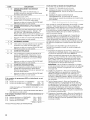
INSTALLATIONINSTRUCTIONS
Excessive Weight Hazard
Use two or more people to move and install washer.
Failure to do so can result in back or other injury.
Max. packed weight:
PD model: 115 kg (253.53 Ib)
PN model: 111 kg (244.71 Ib)
Max. unpacked weight:
PD model: 111 kg (244.71 Ib)
PN model: 107 kg (235.89 Ib)
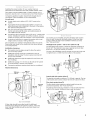
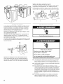
iMPORTANT: Position the washer so that the rear of the washer
is within approximately 900 mm (3 ft.) of its final location.
There are 4 shipping bolts in the rear panel of the washer that
support the suspension system during transportation. These bolts
also retain the power cord inside the washer until the bolts are
removed.
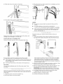
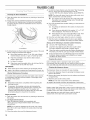
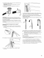
1. Keep the washer in the upright position while removing the
shipping bolts.
Shipping bolt
Shipping bolt with plastic spacer
2. Using a 1/2" wrench, loosen each of the bolts.
3. Once the bolt is loose, move it to the center of the hole
and completely pull out the bolt, including the plastic spacer
covering the bolt.
4. Once all 4 bolts are removed, discard the bolts and spacers.
Then push the plug back into the back of the washer and pull
the power cord through the left opening of the rear panel and
close the hole with the attached cap.
5. Close the bolt holes with the 4 transport bolt hole plugs.
NOTE: If the washer is to be transported at a later date, call your
product distributor or installer. To avoid suspension and structural
damage, your washer must be properly set up for relocation by a
trained professional.
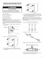
1. Select the plug that fits with the electric receptacle.
2. Assemble the plug into the end of the power cord.
3. Secure the power cord by seating the connection on the cord
lock.
m
4. Place the cord lock cover and push until it snaps.
5. Make sure the power cord connection is seated on the cord
lock and that the cord lock clamps correctly.
7

insert new flat washers (supplied) into each end of the inlet
hoses. Firmly seat the washers in the couplings.
A B
A. Coupling
B. Washer
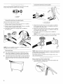
Connect the inlet hoses to water faucets
r; ......................................................................................;; r
Make sure the washer drum is empty.
1. Attach a hose to the hot water faucet. Screw on coupling
by hand until it is seated on the washer.
2. Attach a hose to the cold water faucet. Screw on coupling
by hand until it is seated on the washer.
3. Using pliers, tighten the couplings with an additional
two-thirds turn.
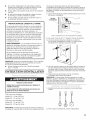
Connect the inlet hoses to the washer
r_
C
2_
3_
4_
C. Cold water inlet
H. Hot water inlet
Attach the hot water hose to the check valve on washer's
hot (H) water inlet valve. Screw on coupling by hand until
it is seated on the check valve.
Attach the cold water hose to the check valve on washer's
cold (C) water inlet valve. Screw on coupling by hand until
it is seated on the check valve.
Using pliers, tighten the couplings with an additional
two-thirds turn.
NOTE: Do not overtighten. Damage to the coupling can result.
Turn on the water taps completely and check for leaks.
C
NOTE: Do not overtighten, use tape, or sealants on the valve.
Damage to the valves can result.
Clear water Hnes
r r r
[] Run water through both faucets and inlet hoses, into a
laundry tub, drainpipe, or bucket, to get rid of particles
in the water lines that might clog the inlet valve screens.
[] Check the temperature of the water to make sure that the
hot water hose is connected to the hot water faucet and
that the cold water hose is connected to the cold water
faucet.
NOTE: Replace inlet hoses after 5 years of use to reduce the risk
of hose failure. Record hose installation or replacement dates on
the hoses for future reference.
Periodically inspect and replace hoses if bulges, kinks, cuts,
wear, or leaks are found.
Remove drain hose from washer drum
1. Use locking pliers, squeeze hose clamp tabs together and
insert over the end of drain hose.
8

2. Slide drain hose onto washer connection.
3. Once drain hose is in place, release pliers.
Washer drain system can be installed using a floor drain, wall
standpipe, floor standpipe, or laundry tub.
Laundry tub drain or standpipe drain
Connect the drain hose form to the corrugated drain hose.
To keep drain water from going back into the washer:
[] Use the drain hose form, and do not force excess drain hose
into standpipe. Hose should be secure, but loose enough to
provide a gap for air.
[] Do not lay excess hose on the bottom of the laundry tub.
Floor drain
You may need additional parts. See Floor drain under "Tools
and Parts."
Drain hose must be secured to stop the hose from moving when
water is pumped out. If the drain hose moves, water may end up
on the floor.
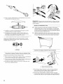
1. Drape the power cord over the washer top.
2. Move the washer to its final location.
3. Place the drain hose in the laundry tub or standpipe as shown.
See illustrations A and B.
L_.JIN {
4
A B C
t
114 mm
(4v_")
NOTES:
[] Do not force excess drain hose back into the rear of the
washer.
[] To avoid siphoning, do not seal or put more than
114 mm (41/2'') of the drain hose into drainpipe or standpipe.
[] If the washer faucets and the drain standpipe are recessed,
put the hooked end of the drain hose in the standpipe as
shown. See illustration C.
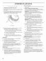
Properly leveling your washer avoids excessive noise and
vibration.
1. Check the levelness of the washer by placing a level on the
top edge of the washer, first side to side, then front to back.
2=
3.
4=
5.
6.
If the washer is against a wall, move the washer out slightly
before tipping back. If the washer is not level, first prop the
front with a wood block and adjust the feet as necessary;
then prop the back and adjust feet as necessary. Repeat this
step until washer is level.
Make sure all four feet are stable and resting on the floor. Then
check that the washer is perfectly level (use a level).
After the washer is level, use a 9/1 6" open-end wrench to turn
the nuts on the feet tightly against the washer cabinet.
IMPORTANT: All four feet must be tightened. If the nuts are
not tight against the washer cabinet, the washer may vibrate.
The washer should not move front to back, side to side,
or diagonally when pushed on its top edges.
Slide the washer to its final location.
Confirm the levelness of the washer.
9

PD Model Washer is coin payment ready and allows the use of
two different sizes of coins if a dual drop is installed. To set-up
the washer for coin payment, acquire a coin drop mechanism
with the appropriate coin sensors. Connect coin sensors to the
coin slot 1 and 2, respectively.
iiiiiii ::ii !ii i ii: i!j iiiiiiiiii!iii :i !iiiii:¸
NOTE: For PD Models only.
1. Take the 2 foam pad strips from bag.
2. Remove tape from the back of adhesive pads.
3. Install the pads on the left and right inside walls of the coin
vault, leaving about 6 mm (1/4") to 13 mm (1/2") of space near
the front edge of the vault to allow room for the coin box to
lock into position.
A. Foam pad strips
1. Check the electrical requirements. Be sure that you have
the correct electrical supply and the recommended earthing
method. See "Electrical Requirements."
2. Check that all parts are now installed, if there is an extra part,
go back through the steps to see which step was skipped.
3. Check that you have all of your tools.
4. Dispose of/recycle all packaging materials.
5. Check that the water taps are on.
6. Check for leaks around taps and inlet hoses.
7.
8.
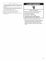
Electric Shock Hazard
Plug into an earthed socket outlet.
Do not use an adapter.
Do not use an extension cord.
Failure to follow these instructions can result in death,
fire, or electric shock.
Plug into an earthed socket outlet.
To test and to clean your washer, measure 1/2 the detergent
manufacturer's recommended amount for a medium-size load.
Pour the detergent into the detergent dispenser. Select any
cycle and allow the washer to complete one whole cycle.
10

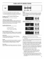
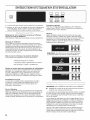
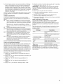
USER&SET.UPINSTRUCTIONS
WHITES COLORS BRIGHTS
PENN. DELICATES QUICK
PRESS AND KNITS CYCLE
1. Door must be closed before cycle selection is made.
2. Press fabric setting button for the wash cycle desired. After
the cycle is started, the time will display and count down.
Scrolling 'out of order' showing in display, followed
by a failure code
This condition indicates the washer is inoperative.
'0 Minutes' showing in display
This condition indicates the washer cannot be operated. Coins
dropped or debit inputs during this condition will be stored in
escrow but cannot be used until normal operation is restored by
opening and closing the door. If a door switch fails, it must be
replaced before normal operation can be restored.
Cold Start (Initial first use)
Washer is programmed at the factory as follows:
Display
After the washer has been installed and plugged in, the display
will show "0 MINUTES." Once the washer has been plugged in
and the washer door opened and closed, the display will show
the price. In washers set for free cycles, the display will flash
"SELECT CYCLE."
WHITES COLORS BRIGHTS
PERM. DELICA33E8 QUICK
PRESS AND F3MITS CYCLE
NOTE: Not displayed on washer as shown. Message scrolls
followed by the failure code.
WHI_8 COLORS BPJGHTS
_ N rm
PERM. DELICATES QUICK
PRESS ANDKNrrs CYCLE
11-minute wash period
3 rinses (extra rinse not enabled)
7 x coin 1 wash price (PD models)
WHl'rl_s COLORS BRIGFn'8
pERM. DELICA'rE8 QUICK
pRESS AND KNITS CYCLE
Warm Start (after power failure)
A few seconds after power is restored, if a cycle was in progress
at the time of the power failure, 'RESELECT CYCLE' will flash in
the display, indicating the need for a key press to restart washer.
WHITES COLORS BRIGHTS
i i !
PERM. DELICATES QUICK
-- PRESS AND KNITS CYCLE
DOOR LOCK
The door will be locked when the cycle starts. The door
will remain locked until the end of a cycle or approximately
2 minutes after a power interruption.
Pricing
After the door is opened following the completion of a cycle, the
display indicates the cycle price (unless set for free operation).
As coins are dropped or debit inputs arrive, the display will
change to lead the user through the initiation of a cycle.
Free Cycles
This is established by setting the cycle price to zero. When this
happens, 'SELECT CYCLE' will appear rather than a cycle price.
IMPORTANT: Read all instructions before operating.
[] PD Models: insert access door key, turn, and lift to remove
access door.
Set-up procedures can be entered by using the Service Access
Code (see service Access Code section) for PN washers set up
without a key switch installed.
The washer is now in the set-up mode. The lower fabric setting
key pads and the digital display are used to set up the controls.
The display can contain 4 numbers and/or letters and a decimal
point. These are used to indicate the set-up codes and related
code values available for use in programming the washer.
Once the washer has been programmed with a hand held device
using Accu Trac, or a Gen. 2 card reader has been installed, the
washer will be put into dAS mode permanently, and dAS will be
displayed every time set-up mode is accessed.
How to use the key pad to program controls
1. The PERM. PRESS button is used to adjust the values
associated with set-up codes. Pressing this button will
change the value by increments. Rapid adjustment is
possible by holding the button down.
2. The DELICATES AND KNITS button advances you through
the set-up codes. Pressing this button will advance you to the
next available set-up code. Holding the button down will
automatically advance through the set-up codes at a rate of
1 per second.
11

3.TheQUICKCYCLEbuttonisusedtoselectordeselect
options.
StartOperatingSet-up
NOTE:Priortooperation,apaymentsystemoranOPLkitmust
beinstalledonPDmodels,aspartoftheset-up.
Beforeproceeding,itisworthnotingthat,despiteallofthe
optionsavailable,anownercansimplychoosetouncrateanew
commercialwasher,hookitup,plugitin,andhaveawasher
thatoperates.Washersarepresetatthefactoryforan11-minute
washperiodand3rinses(noextrarinse).
[] TheDELICATESANDKNITSbuttonwilladvanceyoufrom
codetocode.
[] ThePERM.PRESSbuttonwillchangethecodevalue.
[] TheQUICKCYCLEbuttonwillselectordeselectoptions.
FORPNMODELS:Theset-upcodesarethesameasforthe
"PD"modelexceptwherenoted.
Theset-upcodeisindicatedbytheoneortwoleft-hand
characters.Theset-upcodevalueisindicatedbythetwo
orthreeright-handcharacters.Thefirstcodeshownineach
sectionistheFactoryDefaultsetting.
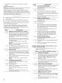
CODE EXPLANATION
6 07 REGULAR CYCLE PRICE (Factory Default)
6 07 Represents the number of coins (Coin 1) needed
to start the washer; may adjust from 0-39. (See
VALUE OF COIN 1.) Advance from 0-39 by
pressing PERM. PRESS button. Factory default
of 7xcoinl.
With coin slide activation, this code represents
the number of push-in actuations of a coin slide
to start the washer.
6 01 setting would represent one coin slide
actuation.
NOTE: For coin slide activation, replacement of
the meter case is necessary.
6 00 PN MODELS ONLY: Factory default for 0 coins.
--> Press the DELICATES AND KNITS button once
to advance to next code.
7 11 WASH LENGTH
7 11 This is the number of minutes for WASH. Washer
comes from the factory preset with 11 minutes.
Choose from 9-17 minutes by pressing the PERM
PRESS button.
--> Press the DELICATES AND KNITS button once to
advance to next code.
NOTE: This option does not apply to QUICK
CYCLE.
8 00 ADDITIONAL RINSE OPTION
This option is either SELECTED 'ON' or NOT
SELECTED 'OFF'.
8 00 Not Selected 'OFF'.
Ar Selected 'ON'. Cannot be combined with the
Super Cycle rinse option.
Press the QUICK CYCLE button once for this
selection.
--> Press the DELICATES AND KNITS button once
to advance to next code.
12
CODE EXPLANAT{ON
9 00 CYCLE COUNTER OPTION
This option is either SELECTED 'ON' or NOT
SELECTED 'OFF'.
9 00 Not Selected 'OFF'.
9 0C Selected 'ON' and not able to be deselected.
Press the QUICK CYCLE button 3 consecutive
times to select 'ON'. Once selected 'ON' it cannot
be deselected.
--> Press the DELICATES AND KNITS button once to
advance to next code.
i t
1. 00 MONEY COUNTER OPTION
This option is either SELECTED 'ON' or NOT
SELECTED 'OFF'.
1. 00 Not Selected 'OFF'.
1. 0C Selected 'ON'.
Press the QUICK CYCLE button 3 consecutive
times to select 'ON' and 3 consecutive times to
remove (Not Selected 'OFF'.) Counter resets by
going from 'OFF' to 'ON'.
--> Press the DELICATES AND KNITS button once
to advance to next code.
1. CO Selected 'ON' and not able to be deselected.
To select 'ON' and not able to be deselected,
first select 'ON', then within 2 seconds, press
the QUICK CYCLE twice, PERM PRESS once,
and exit the set-up mode.
2. 00 SPECIAL PRICING OPTIONS
This option is either SELECTED 'ON' or NOT
SELECTED 'OFF'.
2. 00 Not Selected 'OFF', and next available code will
be A.00.
2. SP Selected 'ON'. Press the QUICK CYCLE button
once for this selection.
if SPECIAL PRiCiNG OPTION is selected, there is access
to codes '3.XX' through '9.XX'.
--> Press the DELICATES AND KNITS button once to
advance to next code.
PN MODELS ONLY: Factory default of 0 coins.
--> Press the DELICATES AND KNITS button once
to advance to next code.
....................................................i
5. 00 TIME-OF-DAY CLOCK, MINUTES
5. 00 This is the TIME-OF-DAY CLOCK, minute setting;
select 0-59 minutes by pressing the PERM.
PRESS button.
--> Press the DELICATES AND KNITS button once
to advance to next code.
6. 00 TIME-OF-DAY CLOCK, HOURS
NOTE: Uses the 24 hr. clock
............................................, r r r r i r
6. 00 This is the TIME-OF-DAY CLOCK, hour setting;
select 0-23 hours by pressing the PERM. PRESS
button.
-->
Press the DELICATES AND KNITS button once
to advance to next code.

CODE EXPLANATION
7.
7.
00 SPEC{AL PRICE START HOUR
NOTE: Uses the 24 hr. clock
00 This is the start hour; 0-23 hours. Select START
HOUR by pressing the PERM. PRESS button.
-> Press the DEL{CATES AND KN{TS button once
to advance to next code.
8. 00 SPECIAL PRICE STOP HOUR
NOTE: Uses the 24 hr. clock
r
8. 00 This is the stop hour; 0-23 hours. Select STOP
HOUR by pressing the PERM. PRESS button.
--> Press the DELICATES AND KNITS button once
to advance to next code.
r r r r r r r
9. 10 SPECIAL PR{CE DAY
r r r rr r r r r r r r r r
9. 10 This represents the day of the week and whether
special pricing is selected for that day. A number
followed by '0' indicates no selection that
particular day (9.10). A number followed by an 'S'
indicates selected for that day (9.1S). To change
the value of '0' and 'S', use the QUICK CYCLE
button.
C. 20 VALUE OF COIN 2
C. 20 This represents the value of coin 2 in the quantity
of 5% increments of the larger coin value. 20 x
5%=100%.
By pressing the PERM. PRESS button, there
is the option of 1-199 for the quantity of 5%
increments.
C. 05
PN MODELS: This represents the value of coin
2 in the quantity of 5% increments of the larger
coin value. Factory default = 5 x 5% of the larger
coin value.
Press the DELICATES AND KNITS button once
to advance to next code.
r
d. 00 COIN SLIDE OPTION
This option is either SELECTED 'ON' or NOT
SELECTED 'OFF'.
r; r r; r; i r; .......................................; r; r; r r
d. 00 Not Selected 'OFF'. Used with coin drop or card
readers.
Selected 'ON'. Press the QUICK CYCLE button
3 consecutive times for this selection.
Days of the week (1-7) are selected by pressing
the PERM. PRESS button.
When exiting set-up code '9', the display must
show current day of week:
DISPLAY DAY OF WEEK CODE (selected)
10 Day 1 = Sunday 1S
20 Day 2 = Monday 2S
30 Day 3 = Tuesday 3S
40 Day 4 = Wednesday 4S
50 Day 5 = Thursday 5S
60 Day 6 = Friday 6S
70 Day 7 = Saturday 7S
--> Press the DELICATES AND KNITS button once
to advance to next code.
...............................................r r; r; ; r r r; ; r
A. 00 VAULT VIEWING OPTION
This option is either SELECTED 'ON' or NOT
SELECTED 'OFF'.
NOTE: This option needs to be set to "00" unless
the meter case has been changed to accept a
coined slide device.
d. CS When coin slide mode is selected 'On', set b.
equal to value of vend price. Set set-up code
6 (regular cycle price) and set-up code 3 (special
cycle price) to number of slide pushes. If washer
is set up as "CS" and a coin drop is installed, it
will not register coins.
NOTE: For coin slide activation, replacement of
the meter case is necessary.
--> Press the DEL{CATES AND KNITS button once
to advance to next code.
r r r r; r r; r
E. 00 ADD COINS OPTION
This option is either SELECTED 'ON' or NOT
SELECTED 'OFF'. This option causes the
customer display to show the number of coins
(coin 1)to enter, rather than the amount.
A. 00 Not Selected 'OFF'. E. 00 Not Selected 'OFF'.
A. SC Selected 'ON'. Press the QUICK CYCLE button
once for this selection. When selected, the money
and/or cycle counts will be viewable (if counting is
selected) when the coin box is removed.
--> Press the DELICATES AND KNITS button once
to advance to next code.
b. 05 VALUE OFCOIN 1
b. 05 This represents the value of coin 1 in the quantity
of 5% increments of the larger coin value. 5 x
5%=25%.
By pressing the PERM. PRESS button, there
is the option of 1-199 for the quantity of 5%
increments.
-->
With coin slide activation, this represents the total
vend price.
NOTE: For coin slide activation, replacement of
the meter case is necessary.
Press the DELICATES AND KNITS button once
to advance to next code.
E. AC Selected 'ON'. Press the QUICK CYCLE button
3 consecutive times for this selection.
--> Press the DELICATES AND KNITS button once
to advance to next code.
R 00 ENHANCED PRICING OPTION
R 00 Not Selected 'OFF'.
F. CP Cycle-Based pricing enabled. This option allows
configuration of different prices for cold, warm,
and hot water cycles.
F. Su Super Cycle pricing enabled. This option allows
customers to upgrade cycles by depositing
extra money. Set-up codes "H." and "h." will be
displayed only when this option is enabled. Press
the QUICK CYCLE button once for this selection.
Press the DELICATES AND KNITS button once
--> to advance to next code.
13

CODE EXPLANATION
H. 01 SUPER CYCLE UPGRADE PRICE
(Skipped unless super cycle pricing is enabled.)
H. 01 This represents the number of coin 1 required to
upgrade a base cycle to a super cycle. Advance
from 0-39 by pressing the PERM. PRESS keypad.
-e Press the DELICATES AND KNITS button once
to advance to next code.
h. 01 SUPER CYCLE TYPE
(Skipped unless Super Cycle pricing is enabled.)
h. 01 This represents the Super Cycle upgrade option.
Press the PERM. PRESS button to step through
upgrade options 1-3 as follows:
01 - enhanced wash, extra 3 minutes of wash
tumble in addition to the programmed wash time.
02 - extra rinse for all cycles.
03 - both 01 and 02.
--> Press the DELICATES AND KNITS button once
to advance to next code.
............................................... t
J. Cd COIN/DEBIT OPTION
...............................................i
J. Cd Both coin & debit selected. Press the QUICK
CYCLE button 3 consecutive times to change this
section.
J. C_ Coins selected, debit disabled. Press the QUICK
CYCLE button 3 consecutive times to change this
selection.
J. _d Debit card selected, coins disabled. This is the
factory default for PN models. Press the QUICK
CYCLE button 3 consecutive times to change this
selection.
J. Ed Enhanced Debit is self-selected when a
Generation 2 card reader is installed in the
washer. The Ed option cannot be manually
selected or deselected.
--> Press the DELICATES AND KNITS button once
to advance to next code.
L. 00 PRICE SUPPRESSION OPTION
This option causes the customer display to show
'ADD' or 'AVAILABLE' rather than the amount of
money to add. (Used mainly in debit installations.)
L. 00 Not Selected 'OFR'
L. PS Selected 'ON.' Press the QUICK CYCLE button
once for this selection.
--> Press the DELICATES AND KNITS button once
to advance to next code.
n. CE CLEAR ESCROW OPTION
When selected, money held in escrow for
30 minutes without further escrow or cycle
activity will be cleared.
00 Not Selected 'OFF'.
CE Selected 'ON'. Press the QUICK CYCLE button
once for this selection.
--> Press the DELICATES AND KNITS button once
to advance to next code.
CODE EXPLANATION
r. 800 TOPSPiN SPEED RPM
r. 800 This can be selected from the following spin
speeds: 600 rpm, 750 rpm, 800 rpm, 1000
(displays as 999) rpm. Step between speeds by
pressing the PERM. PRESS button. Factory
pre-set for 800 rpm.
-e Press the DELICATES AND KNITS button once
to advance to next code.
U. 00 PENNY INCREMENT OFFSET
U. 00 This option is not supported for European Models
and the value must be set to 00.
-e Press the DELICATES AND KNITS button once
to advance to next code.
A1. 00 PREWASH LENGTH
Choose 0 to disable the prewash or select
between 2 and 7 minutes by pressing the PERM.
PRESS button.
--> Press the DELICATES AND KNITS button once
to advance to next code.
A2. 03 FINAL SPiN LENGTH
A2. 03 This is the number of minutes of final high speed
spin. Choose from 3-8 minutes by pressing the
PERM. PRESS button.
--> Press the DELICATES AND KNITS button once
to advance to next code.
If cycle counter (9 0C) is selected, the following is true:
1 00 Number of cycles in HUNDREDS. 1 02 = 200
2 00 Number of cycles in ONES. 2 2`5= 25
TOTAL CYCLES = 225
This is 'VIEW ONLY' and cannot be cleared.
--> Press the DELICATES AND KNITS button once to
advance to next code.
If money counter (1.0C or 1.00) is selected, the following
is true:
3 00 Currency amount in HUNDREDS.
4 00 Currency amount in ONES.
5 00 Currency amount in HUNDREDTHS.
END OF SET-UP PROCEDURES
301=100.00
4 68 = 68.00
5 7,5 = 00.75
TOTAL = 168.75
EXIT FROM SET=UP MODE
[] PD Models: Reinstall access door.
[] PN MODELS WiTH PROGRAMMING SWITCH:
Turn key clockwise and remove.
[] PN MODELS WITHOUT PROGRAMMING SWITCH:
Set-up mode can be exited by using procedures from the
Service Access Code section.
14

,¸ !ii! i,iiiiiiiiio :! ::! ii
To enter the "Washer Diagnostic Mode," first enter "Start
Operating Set-up." Then press and hold the QUICK CYCLE
button for 1 second while in set-up code 6, anytime a diagnostic
code is present, or while dAS displays if operating with Maytag
Data Acquisition set-up.
On entry to diagnostic mode the entire display will flash, a
cycle in process is canceled, money in escrow is cleared, and
diagnostic codes are cleared, if a diagnostic code persists,
it must be corrected before the following cycle options are
permitted.
There are five possible ways to initiate cycle activity from
diagnostic mode as follows:
1. Washer Cleanout cycle - With the entire display flashing, this
cycle is started by pressing the BRIGHTS button.
Use the Washer Cleanout cycle once a month to keep the
inside of your washer fresh and clean. This cycle uses
a higher water level. Use with liquid chlorine bleach to
thoroughly clean the inside of the washer. This cycle should
not be interrupted.
IMPORTANT: Do not place garments or other items in the
washer during the Washer Cleanout cycle. Use this cycle with
an empty wash drum.
2. Cycle Credit - With the entire display flashing, a cycle may
be credited by pressing the PERM. PRESS button (CC will
display). When the service mode is exited, "SELECT CYCLE"
will be displayed unless the end-of-cycle door opening is
required.
3. Manual Overview Test - With the entire display flashing, this
cycle is started by pressing the WHITES button. This cycle
provides more typical full length fills, tumbles, drains, and
actuator dispenser movement, allowing for a more thorough
analysis of the washer operation, including pressure switch
behavior.
4. Quick Spin Cycle - With the entire display flashing, this
cycle is started by pressing the COLORS button. This cycle
provides a method to quickly drain and spin (remove water
from the washer) if desired.
5. Quick Overview Test - With the entire display flashing, this
cycle is started by pressing the DELICATES AND KNITS
button. This cycle provides a quick verification that the cold
and hot water valves, dispensers, and pump motor are
working, as well as actuator dispenser movement. It also
includes door lock, drain, and spin operations.
Pressing the QUICK CYCLE button will exit diagnostic mode
and cancel a diagnostic cycle in process.
DIAGNOSTIC CODES
If one of the following has occurred, the appropriate diagnostic
code will be in the display.
d5 Blocked coin 1 or coin drop control circuit failure (coin
recognition and price display disabled while blockage
persists).
PN Models Only: Set-up mode J. should be set
to d to eliminate coin related diagnostic codes.
d9 Low voltage detected for 8 seconds.
d13 Blocked coin 2 or coin drop control circuit failure (coin
recognition and price display disabled while blockage
persists).
F20 Slow Fill. The washer will not detect water input for 4 min.
Pressure switch failure or no water inlet. This code is
reported as d8 on d7.
F22 The door is not able to lock. Door lock error or someone
trying to start the washer, by pressing the door switch
with the finger. This code is reported as dl 7 on Accu Trac.
(For any other codes, check supplied Technical Sheet)
SERVICE ACCESS CODE
This code can be entered to access service mode without
removing the console. It only functions on washers set up for
0 vend price without any Special Pricing set-up, and the Coin/
Debit Option must be set to "J. d". If the washer is not in failure
mode, the door must be opened to proceed. Service Access
Code contains 6 steps and some are timed. Using only the three
bottom buttons (numbered 1,2, and 3 from left to right):
1. Press 2 for longer than 2 seconds but less than 10 seconds.
2. Press 1 & 3 together for 2 seconds, then release.
Displays S 3.
3. Press 1 & 2 together, then release. Displays S 4.
4. Press 2 & 3 together, then release. Displays S 5.
5. Press 2, then release. Display shows "codE".
6. Wait at least 2 seconds, but not more than 15 seconds, then
press in succession: 3, 2, 1, 3.
NOTE: If the Service Access Code procedure is not completed
properly, as noted above, there is a 15 second delay before it can
be attempted again.
There are 3 options to exit from the Service Mode:
1. From Set-up Code 8, press key #1 for 4 seconds.
2. Wait 2 minutes without touching any buttons (without
diagnostic modes running).
3. Power down the washer, then reapply power.
WASHER HELP MODE
This mode is entered by pressing the PERM. PRESS button while
in special pricing option mode 2.XX (or while dAS displays if
operating with Maytag Data Acquisition set-up).
In help mode, other display symbols and elements are mapped to
reflect the state of various inputs and outputs as follows:
Display Symbol Description
Wash Water sensed at wash level.
* Low voltage present (below about
90 VAC).
° (Circle above digit) Door closed
DOOR LOCKED Door sensed locked.
COLD Cold water relay on.
HOT Hot water relay on.
OR Door unlock.
AVAILABLE Drain pump ON.
NOTE: A Technical Sheet is supplied taped to inside of lower
front panel, which includes fault codes and a machine schematic
diagram.
15

Ciiiii ii! iJ :/i i:iiiil;¸ '¸
WASHER CARE
Cleaning the Door Seal/Bellow
1. Open the washer door and remove any clothing or items from
the washer.
2. Inspect the colored seal/bellow between the door opening
and the drum for stained areas. Pull back the seal/bellow
to inspect all areas under the seal/bellow and to check for
foreign objects.
4. To start the Clean Washer cycle, first enter "Start Operating
Set-up." Then press and hold QUICK CYCLE for
1 second. With the entire display flashing, press BRIGHTS.
NOTE: The drum will rotate, then the door will unlock, lock
again, and then the cycle will continue.
[] The washer will not fill, but the drum will rotate while
the washer runs a short sensing cycle. This will take
approximately 3 minutes.
5. The cycle will determine whether clothing or other items are
in the washer.
a} If no items are detected in the washer, it will proceed
to Step 7.
b} If any items are detected in the washer, "rL" or "F-34"
will be displayed. Then the door will unlock.
[] Press QUICK CYCLE to cancel the failure code. Then
repeat steps 1, 3, and 4 to start the cycle again.
6. Once the cycle has begun, allow the cycle to complete.
7. After the cycle is complete, leave the door open slightly,
to allow for better ventilation and drying of washer interior.
A
A. Seal/Bellow
3. If stained areas are found, wipe down these areas of the seal/
bellow, using the procedure that follows.
a} Mix a dilute solution, using 177 mL (3/4 cup) of liquid
chlorine bleach, and 3.8 L (1 gal. ) of warm tap water.
b} Wipe the seal/bellow area with the dilute solution,
using a damp cloth.
c} Let stand 5 minutes.
d} Wipe down area thoroughly with a dry cloth and let the
washer interior air dry with door open.
IMPORTANT:
[] Wear rubber gloves when cleaning for prolonged periods.
[] Refer to the bleach manufacturer's instructions for proper use.
Washer Maintenance Procedure
This washer has a special cycle that uses higher water volumes
in combination with liquid chlorine bleach to thoroughly clean
the inside of the washer.
NOTES:
[]
[]
Read these instructions completely before beginning the
cleaning process.
If necessary, the cleaning cycle may be interrupted by
pressing the QUICK CYCLE button twice. However, this
will not immediately stop the cycle. The washer will
continue with several rinse and drain steps to ensure that
all remaining bleach is rinsed from the washer.
Begin procedure
1. Open the washer door and remove any clothing or items from
the washer.
2, Use liquid chlorine bleach:
Open the dispenser drawer and immediately add
160 mL (2/3 cup) of liquid chlorine bleach to the bleach
compartment.
NOTE: Do not add any detergent to this cycle. Use of more
than 160 mL (2/3 cup) of bleach will cause product damage
over time.
Always do the following to maintain washer freshness
[] Use only "HE" High Efficiency detergent.
[] Leave the door slightly open after each cycle to allow
for better ventilation and drying of washer interior.
[] Clean the washer monthly using the Washer Maintenance
Procedure, and 160 mL (2/3 cup) of liquid chlorine bleach.
[] if the procedure does not sufficiently improve the machine
freshness, please evaluate your installation and usage
conditions for other causes.
Cleaning the exterior
;r r; r i r ............ r
Use a soft damp cloth or sponge to wipe up any spills.
Occasionally wipe the outside of your washer to keep it looking
new. Use mild soap and water. Do not use abrasive products.
................................................................r ;; ;
Cleaning the dispenser drawer
r r
The dispenser drawer is removable for easy cleaning.
1. Unlock the dispenser drawer by pressing the Release Lever.
Remove the drawer.
2. Remove the inserts (the siphon from the softener and bleach
compartments).
3. Wash the parts under running water.
NOTE: Do not wash components in the dishwasher.
4. Replace the inserts and return the dispenser to the drawer.
Replace water inlet hoses after 5 years of use to reduce the risk
of hose failure. Periodically inspect and replace water inlet hoses
if bulges, kinks, cuts, wear, or leaks are found.
When replacing your water inlet hoses, mark the date of
replacement on the label with a permanent marker.
3. Close the washer door and the dispenser drawer.
16

ASSISTANCEORSERVICE
If you need help, contact the dealer from whom you purchased
the appliance, or a Maytag designated service company. When
calling, please know the purchase date and the complete model
and serial number of your appliance. This information will help us
to better respond to your request.
Enhance your washer with these premium accessories.
For more high-quality items or to order, contact your authorized
Maytag distributor.
Part Number Accessory
8212526 Washer drip trays, fits under all
31682 All purpose appliance cleaner
1903WH Laundry supply storage cart
Whirlpool Corporation, Benton Harbor, Michigan 49022, USA.
Manufacturer site: Whirlpool Mexico S.A. de C.V.,Antigua Carretera a Roma Km 9, Col.
El Milagro, Apodaca, Nuevo Leon, C.R 66634, Mexico.
EU representative: Maytag UK Ltd, Redhill, RH1 lAX, UK
BAUKNECHT HAUSERGR)i,TEGrab H, D-73614 Schorndorf
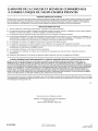
MAYTAG ® COMMERCIAL SINGLE-LOAD AND VENDED
MULTI-LOAD WASHER & DRYER
WARRANTY
LIMITED WARRANTY ON PARTS
For the first five years from the date of purchase, when this commercial appliance is installed, maintained and operated according to the
instructions attached to or furnished with the product, Maytag brand of Whirlpool Corporation (thereafter "Maytag") will pay for factory
specified parts or original equipment manufacturer parts to correct defects in materials or workmanship. Proof of original purchase date
is required to obtain service under this warranty.
ITEMS MAYTAG WILL NOT PAY FOR
1. All other costs including labor, transportation, or custom duties.
2. Service calls to correct the installation of your commercial appliance, to instruct you how to use your commercial appliance, to
replace or repair fuses, or to correct external wiring or plumbing.
3. Repairs when your commercial appliance is used for other than normal, commercial use.
4. Damage resulting from improper handling of product during delivery, theft, accident, alteration, misuse, abuse, fire, flood, acts of
God, improper installation, installation not in accordance with local electrical or plumbing codes, or use of products not approved
by Maytag.
5. Pickup and Delivery. This commercial appliance is designed to be repaired on location.
6. Repairs to parts or systems resulting from unauthorized modifications made to the commercial appliance.
7. The removal and reinstallation of your commercial appliance if it is installed in an inaccessible location or is not installed in
accordance with published installation instructions.
8. Chemical damage is excluded from all warranty coverage.
9. Changes to the building, room, or location needed in order to make the commercial appliance operate correctly.
10. Repairs made by a non-Whirlpool authorized service technician.
DISCLAIMER OF IMPLIED WARRANTIES; LIMITATIONS OF REMEDIES
CUSTOMER'S SOLE AND EXCLUSIVE REMEDY UNDER THiS LIMITED WARRANTY SHALL BE PRODUCT REPAIR AS PROVIDED
HEREIN. IMPLIED WARRANTIES, INCLUDING WARRANTIES OF MERCHANTABILITY OR FITNESS FOR A PARTICULAR PURPOSE,
ARE LIMITED TO ONE YEAR OR THE SHORTEST PERIOD ALLOWED BY LAW. WHIRLPOOL SHALL NOT BE LIABLE FOR
INCIDENTAL OR CONSEQUENTIAL DAMAGES. SOME STATES AND PROVINCES DO NOT ALLOW THE EXCLUSION OR LIMITATION
OF INCIDENTAL OR CONSEQUENTIAL DAMAGES, OR LiMiTATIONS ON THE DURATION OF IMPLIED WARRANTIES OF
MERCHANTABILITY OR FITNESS, SO THESE EXCLUSIONS OR LIMITATIONS MAY NOT APPLY TO YOU. THIS WARRANTY GIVES
YOU SPECIFIC LEGAL RIGHTS AND YOU MAY ALSO HAVE OTHER RIGHTS, WHICH VARY FROM STATE TO STATE OR PROVINCE
TO PROVINCE.
if you need service, please contact your authorized Maytag ® Commercial Laundry distributor. To locate your authorized Maytag ®
Commercial Laundry distributor, or for web inquiries, visit www.MaytagCommercialLaundry.com.
3/1o
For written correspondence:
Maytag ® Commercial Laundry Service Department
2000 M-63 North
Benton Harbor, Michigan 49022 USA
17

Whir ®
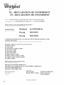
EU- DECLARATION OF CONFORMITY
CE - DECLARATION DE CONFORMITE
WE (nolts): BAUKNECHT HAUSGERA_TE GmbH, D-73614 Schorndorf
representing (repr&'entant): WHIRLPOOL EUROPE S.r.1 I-21025 COMERIO
declare under our sole responsibility that the product
d_c/arons solts notre propre res]_onsabilit_ ctlte /e prodltit
washing machines
(machine ?4 laver le linge) :
Whirlpool
Maytag
3LCHW9100YQ
MHN30PN
Maytag
MHN30PD
to which this declaration relates is in conformity with the following standard(s) or other
normative document(s)
altctltel se r_f_re cette d_claration est col_fbrme altx normes sltivantes olt alttres docltments normatif_'
EN 60335-1:2002+Al+A2+All+A12+A13+A14+A15
EN 60335-2-7:2010
EN 62233:2008
EN 61770:1999+Al:2004+A2:2006
EN ISO 10472-1:2008
EN ISO 10472-2:2008
EN ISO 12100-1:2010
EN 55014-1:2006+A1:2009
EN 55014-2:1997+Al:2001+A2:2008
EN 61000-3-2:2006+Al:2009+A2:2009
EN 61000-3-3:2008
following the provisions of Directive(s):
sltivant les pr_visions des' Directives:
2006/42/EC MACHINERY DIRECTIVE
2004/108/EC ELECTROMAGNETIC COMPATIBILITY DIRECTIVE
2011/65/EU ROHS DIRECTIVE
2002/96/EC WEEE DIRECTIVE
represented by
Schorndorf, 01.06.2012 Micael Zirondi
Place and date: Director PDC FC EMEA
lieu et date
Karl-Dieter Klingenstein
Product Approval
GPO, Schorndorf
18
Name and siNlal_ue of a_uthorisedperson
_llz et sigllamre de lapersolllle autorisde

P P
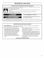
SECURITEDULAVE-LINGE
Votre s_curit_ et celle des autres est tr_s importante.
Nous donnons de nombreux messages de securit6 importants dans ce manuel et sur votre appareil menager. Assurez-vous de
toujours lire tousles messages de s6curit6 et de vous y conformer.
Voici le symbole d'alerte de securit6.
Ce symbole d'alerte de s6curit6 vous signale les dangers potentiels de d6c_s et de blessures graves &vous
et & d'autres.
Tousles messages de s6curit_ suivront le symbole d'alerte de s6curit6 et le mot "DANGER" ou
"AVERTISSEMENT'. Ces mots signifient :
Risque possible de d_c_s ou de blessure grave si vous ne
suivez pas imm6diatement les instructions.
Risque possible de d_c_s ou de blessure grave si vous
ne suivez pas les instructions.
Tousles messages de s6curit6 vous diront quel est le danger potentiel et vous disent comment r_duire le risque de blessure et
ce qui peut se produire en cas de non-respect des instructions.
llVIPORTANTES iNSTRUCTiONS DE SECURITE
AVERTISSEMENT : Pour r6duire les risques d'incendie, de choc electrique ou de blessures Iors de I'utilisation de la
laveuse, suivre les pr6cautions fondamentales dont les suivantes :
[] Dans certaines conditions, de I'hydrog_ne gazeux
peut se former dans un circuit d'eau chaude qui n'a
pas _t6 utilis6 pendant 2 semaines ou plus. LE GAZ
HYDROGC:NE EST EXPLOSIBLE. Si le circuit d'eau
chaude n'a pas 6t6 utilis6 pendant une telle p6riode,
avant d'utiliser la laveuse, ouvrir tousles robinets
d'eau chaude et laisser I'eau s'6couler pendant
plusieurs minutes par chaque robinet. Ceci
permettra I'evacuation de I'hydrog_ne gazeux
accumul6. Comme ce gaz est inflammable, ne pas
fumer ou utiliser une flamme nue au cours de cette
p6riode.
[] Avant de mettre la laveuse au rebut ou hors de service,
enlever la porte ou le couvercle.
[] Ne pas installer ou remiser cette laveuse & un endroit ot_elle
serait expos6e aux intemperies.
[] Ne pas r6parer ou remplacer un composant quelconque de
la laveuse, ni entreprendre une op6ration de service, si ce
n'est specifiquement recommand6 dans ce manuel ou dans
un manuel d'instructions de reparations destine h I'utilisateur;
il est alors essentiel que la personne concernee comprenne
ces instructions et soit competente pour les ex_cuter.
[] Voir "Specifications electriques" pour les instructions de
liaison a la terre.
CONSERVEZ CES iNSTRUCTiONS
19

MISEAUREBUT DU LAVE.LINGE
Le marquage de rappareil est conforme h la directive europ6enne 2002/96/EC sur les 6quipements 61ectroniques et
dlectriques, pour gestion des d6chets.
En veillant & 1'61imination correcte de ce produit, vous 6viterez d'dventuelles consdquences n6fastes pour I'environnement et la
sant6 humaine qui peuvent _tre associ6es au traitement inapproprid de ce produit Iorsqu'il a 6t6 mis au rebut.
Le symbole figurant sur le produit ou dans les documents qui accompagnent le produit indique que cet appareil ne dolt pas 6tre
trait6 comme d6chet m6nager; on dolt plut6t le remettre hun centre de collecte spdcialis6 pour le recyclage des 6quipements
61ectriques et 61ectroniques.
L'61imination de ce produit apres mise au rebut dolt _tre effectuee conformement aux prescriptions de la reglementation locale
de protection de I'environnement.
Pour I'information detaill6e concernant le traitement, le recyclage et la recup6ration de ce produit, contacter la municipalite
locale, le service d'61imination des ddchets m_nagers, ou le commergant qui a vendu le produit.
Nomenclature des modules
MHN - Maytag 30 - Numdro de type de modele
PN - Module de commande dlectronique sans paiement
PD - Module de commande dlectronique avec chute de piece activd
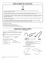
EXIGENCESD'INSTALLATION
Rassembler les outils et pieces ndcessaires avant de commencer
I'installation. Les pieces fournies se trouvent dans le tambour du
lave-linge.
Pi_ces fournies
A B
Outils n_cessaires au raccordement des tuyaux d'arriv_e
d_eau
[] Pince (ouverture jusqu'& [] Lampe de poche
39,5 mm [19/16"]) (facultative)
Outils ndcessaires _ I'installation
[] Clds plates de 1/2" et [] Niveau
9/16"
[] Cale en bois
[] Tournevis de sdcuritd [] Regle ou metre ruban
Torx_l -I--20
[] Tourne-dcrou de 1/4"
c
A. Bride de retenue pour tuyau de vidange (en forme de U)
B. Tuyaux d'arrivee d'eau (2)
C. Rondelles pour tuyau d'arrivee d'eau (4)
D. Bouchons pour les trous des boulons de transport (4)
E. Attache de fixation amovible
F. Tuyau de vidange
G. Bride de tuyau
Pi_ces fournies pour les modules PD :
Came de verrouillage de
la porte de service
Bandes de protection
1® TORXest une marque d6pos6e de Saturn Fasteners,Inc.
20
La page est en cours de chargement...
La page est en cours de chargement...
La page est en cours de chargement...
La page est en cours de chargement...
La page est en cours de chargement...
La page est en cours de chargement...
La page est en cours de chargement...
La page est en cours de chargement...
La page est en cours de chargement...
La page est en cours de chargement...
La page est en cours de chargement...
La page est en cours de chargement...
La page est en cours de chargement...
La page est en cours de chargement...
La page est en cours de chargement...
La page est en cours de chargement...
-
 1
1
-
 2
2
-
 3
3
-
 4
4
-
 5
5
-
 6
6
-
 7
7
-
 8
8
-
 9
9
-
 10
10
-
 11
11
-
 12
12
-
 13
13
-
 14
14
-
 15
15
-
 16
16
-
 17
17
-
 18
18
-
 19
19
-
 20
20
-
 21
21
-
 22
22
-
 23
23
-
 24
24
-
 25
25
-
 26
26
-
 27
27
-
 28
28
-
 29
29
-
 30
30
-
 31
31
-
 32
32
-
 33
33
-
 34
34
-
 35
35
-
 36
36


Maytag MHN30PDAGW Guide d'installation
- Catégorie
- Machines à laver
- Taper
- Guide d'installation
- Ce manuel convient également à
dans d''autres langues
- English: Maytag MHN30PDAGW Installation guide
Documents connexes
-
Maytag MHN30PNBGW Installation Instructions Manual
-
-
-
-
-
Maytag MHN31PRAWW Installation Instructions Manual
-
-
Maytag MLG20PDCWW0 Guide d'installation
-
-