W10722893B
INSTALLATION INSTRUCTIONS
CommerCial Washer
INSTRUCTIONS D’INSTALLATION
lave-linge CommerCial
INSTRUCCIONES DE INSTALACIÓN
lavadora ComerCial
ISTRUZIONI D’INSTALLAZIONE
lavatriCe CommerCiale
www.maytagcommerciallaundry.com
MVW18CS
MVW18MN
MVW18PD

2
TABLE OF CONTENTS
Page
Washer Safety .......................................................................... 3
Washer Disposal ...................................................................... 4
Tools & Parts ............................................................................ 5
Dimensions .............................................................................. 6
Location Requirements ...........................................................7
Drain System ............................................................................ 8
Electrical Requirements..........................................................8
Installation Instructions .......................................................... 9
Connect Drain Hose .............................................................. 10
Connect Inlet Hoses .............................................................. 11
Level Washer .......................................................................... 12
Installing Coin Slide and Coin Box ....................................... 12
Complete Installation ............................................................ 13
Typical Full Load Sizes .......................................................... 13
Washer Maintenance.............................................................14
If You Need Assistance ......................................................... 15
Alternate Parts & Accessories ............................................. 15
Electronic Controls Set-up Instructions .............................. 16
Warranty ................................................................................. 20
TABLE DES MATIÈRES
Page
Sécurité du lave-linge ........................................................... 21
Élimination du lave-linge ...................................................... 22
Outillage et pièces ................................................................. 22
Dimensions ............................................................................ 23
Exigences d’emplacement ................................................... 24
Système de vidange .............................................................. 25
Spécications électriques .................................................... 26
Instructions d’installation ..................................................... 27
Raccordement du tuyau de vidange .................................... 28
Raccordement des tuyaux d’arrivée d’eau ......................... 29
Établissement de l’aplomb du lave-linge ............................ 30
Installation de la glissière et de la boîte à monnaie ........... 30
Achever l’installation ............................................................. 31
Taille typique des charges complètes ................................. 31
Entretien du lave-linge .......................................................... 32
Si vous avez besoin d’assistance ........................................ 33
Pièces supplémentaires et accessoires .............................. 33
Instructions de paramétrage des commandes
électroniques .........................................................................34
Garantie .................................................................................. 39
ÍNDICE
Página
Seguridad de la lavadora ...................................................... 40
Eliminación de la lavadora .................................................... 41
Herramientas y piezas .......................................................... 41
Dimensiones .......................................................................... 42
Requisitos de ubicación ....................................................... 43
Sistema de desagüe .............................................................. 44
Requisitos eléctricos ............................................................ 44
Instrucciones de instalación ................................................ 45
Conexión de la manguera de desagüe ................................ 46
Conexión de las mangueras de entrada ............................. 47
Nivelación de la lavadora ...................................................... 48
Instalación del tragamonedas y la caja de monedas ......... 48
Complete la instalación ....................................................... 49
Tamaños de cargas típicas de volumen completo .............49
Mantenimiento de la lavadora .............................................. 50
Si necesita asistencia ........................................................... 51
Piezas y accesorios alternativos ......................................... 51
Instrucciones para programar los controles
electrónicos ...........................................................................52
Garantía .................................................................................. 57
SOMMARIO
Pagina
Sicurezza della lavatrice ....................................................... 58
L’eliminazione della lavatrice ............................................... 59
Attrezzi e componenti ........................................................... 59
Dimensioni ............................................................................. 60
Requisiti di posizionamento ................................................. 61
Sistema di scarico ................................................................. 62
Requisiti elettrici .................................................................... 62
Istruzioni d’installazione ....................................................... 63
Connessione del tubo di scarico ......................................... 64
Collegare i tubi d’ingresso .................................................... 65
Livellamento della lavatrice .................................................. 66
Installazione dello scivolo monete e della gettoniera ........ 66
Completamento dell’installazione ....................................... 67
Dimensioni tipiche a carico completo ................................. 67
Manutenzione lavatrice ......................................................... 68
Se avete bisogno dell’assistenza ......................................... 69
Parti e accessori alternativi .................................................. 69
Istruzioni di congurazione dei comandi elettronici ..........70
Garanzia ................................................................................. 75

3
WASHER SAFETY

4
WASHER DISPOSAL
This appliance is marked according to the European directive 2012/19/EU on Waste Electrical and Electronic Equipment
(WEEE).
By ensuring this product is disposed of correctly, you will help avoid potential negative consequences for the environment
and human health, which could otherwise be caused by inappropriate waste handling of this product.
The symbol on the product, or on the documents accompanying the product, indicates that this appliance may not be
treated as household waste. Instead it shall be handed over to the applicable collection point for the recycling of electrical
and electronic equipment.
Disposal must be carried out in accordance with local environmental regulations for waste disposal.
For more detailed information about treatment, recovery and recycling of this product, please contact your local city ofce,
your household waste disposal service or the shop where you purchased the product.

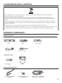
5
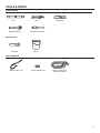
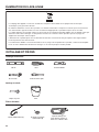
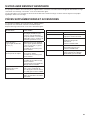
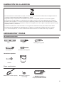
Parts Supplied:
Water Inlet Hoses (2) Inlet Hose Washers (4)
TOOLS & PARTS
Tools Needed:
Level Pliers
Utility Knife
Adjustable Wrench Flat-Blade Screwdriver
Drain hose with clamp,
U-form, and cable tie
Optional tools:
Flashlight Bucket

6
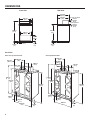
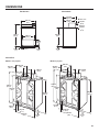
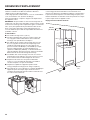
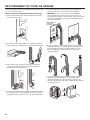
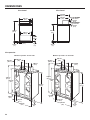
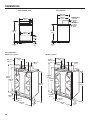
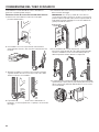
DIMENSIONS
Front View Side View
Back View
Non-coin-operated models Coin-operated models
25 mm
(1")
686 mm
(27")
108 mm
(4
1
/2")
914 mm
(36")
1,047 m
(41
1
/4")
165 mm
(6
1
/2")
902 mm
(35
1
/2")
406 mm
(16")
267 mm
(10
1
/
2
")
140 mm
(5
1
/2")
67 mm
(2
5
/8")
267 mm
(10
1
/2")
16 mm
(
5
/8")
686 mm
(27")
546 mm
(21
1
/2")
1,047 m
(41
1
/4")
25 mm
(1")
889 mm
(35")
25 mm
(1")
Non-coin-operated
models:
159 mm
(6
1
/4")
Coin-operated
models:
210 mm
(8
1
/4")
699 mm
(27
1
/2")
686 mm
(27")
1,098 m
(43
1
/4")
686 mm
(27")
108 mm
(4
1
/4")
165 mm
(6
1
/2")
914 mm
(36")
902 mm
(35
1
/2")
267 mm
(10
1
/2")
406 mm
(16")
140 mm
(5
1
/2")
25 mm
(1")
.
.
.

7
Selecting the proper location for your washer improves
performance and minimizes noise and possible washer “walk.”
Your washer can be installed in a basement, laundry room, or
recessed area. See “Drain System.”
Companion appliance location requirements should also be
considered.
IMPORTANT: Do not install or store the washer where it will be
exposed to the weather. Do not store or operate the washer in
temperatures at or below 0°C (32°F). Some water can remain in
the washer and can cause damage in low temperatures. Proper
installation is your responsibility.
You will need:
n A water heater set to 49°C (120°F).
n An earthed electrical outlet located within 1.2 m (4 ft.) of
power cord on back of washer. See “Electrical Requirements.”
n Hot and cold water faucets located within 1.2 m (4 ft.) of hot
and cold water ll valves on washer, and water pressure
of 138-690 kPa (20-100 psi). A pressure reduction valve
should be used in the supply line where inlet pressure
entering the building exceeds 690 kPa (100 psi) to avoid
damage to the washer mixing valve.
n Single washer installations require 300 mm (12") minimum
risers to provide an air cushion and avoid noise and damage
to valves.
n A level oor with maximum slope of 25 mm (1") under entire
washer. Installing on carpet is not recommended.
n
Floor must support washer’s total weight (with water and load)
of 143 kgs (315 lbs).
n A oor drain under the bulkhead. Prefabricated bulkheads
with electrical outlets, water inlet lines, and drain facilities
should be used only where local codes permit.
LOCATION REQUIREMENTS
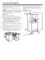
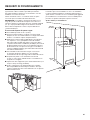
Recessed Area or Closet Installation
This washer may be installed in a recessed area or closet.
The installation dimensions shown are the minimum spaces
allowable. Additional spacing should be considered for ease of
installation and servicing. Companion appliance spacing should
be considered.
Minimum installation spacing
356 mm
(14" max.)
457 mm
(18")
457 mm
(18")
25 mm
(1")
25 mm
(1")
127 mm
(5")

8
DRAIN SYSTEM
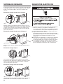
ELECTRICAL REQUIREMENTS
n
A 220-240 volt, 50 Hz., AC only, 10-amp, fused electric supply is
required. A time-delay fuse or circuit breaker is recommended. It
is recommended that a separate circuit serving only this appliance
be provided.
n
After installation, access to mains plug or disconnection from
mains supply via a double-pole switch, must be ensured at all
times in order to ensure immediate deactivation of the washer
in case of emergency.
n
This washer is equipped with a power supply cord having an
earthing plug. The plug should be accessible for disconnection
from the supply.
n
If the supply cord is damaged, it must be replaced by the
manufacturer, its service agent, or similarly qualied persons
in order to avoid a hazard.
Drain system can be installed using a oor drain, wall standpipe,
oor standpipe, or laundry tub. Select method you need.
Floor standpipe drain system
Minimum diameter for a standpipe drain: 51 mm (2"). Minimum
carry-away capacity: 38 L (10 gal.) per minute. Top of standpipe
must be at least 990 mm (39") high; install no higher than
2.44 m (96") from bottom of washer.
Laundry tub drain system
990 mm
(39")
114 mm
(4,5")
990 mm
(39")
114 mm
(4,5")
Wall standpipe drain system
710 mm
(28")
See requirements for oor standpipe drain system.
Floor drain system
Floor drain system requires a Siphon Break Kit (Part Number
285834). Minimum siphon break: 710 mm (28") from bottom
of washer. Additional hoses may be needed.
.
.
114 mm
(4,5")
.

9
EARTHING INSTRUCTIONS
This washer must be earthed. In the event of a malfunction
or breakdown, earthing will reduce the risk of electric
shock by providing a path of least resistance for electric
current. This washer is equipped with a cord having an
equipment-earthing conductor and an earthing plug. The
plug must be plugged into an appropriate outlet that is
properly installed and earthed in accordance with all local
codes and ordinances.
WARNING: Improper connection of the equipment-
earthing conductor can result in a risk of electric shock.
Check with a qualified electrician or serviceman if you are in
doubt as to whether the appliance is properly earthed.
Do not modify the plug provided with the appliance – if it will
not fit the outlet, have a proper outlet installed by a qualified
electrician.
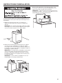
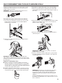
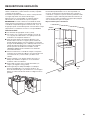
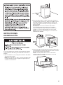
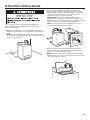
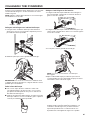
INSTALLATION INSTRUCTIONS
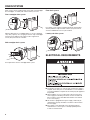
It is necessary to remove all shipping materials for proper
operation and to avoid excessive noise from washer.
1. Move washer to within 1.2 m (4 ft) of its nal location; it must
be in a fully upright position.
NOTE: To avoid oor damage, set washer onto cardboard
before moving it and make sure lid is taped shut.
2. To avoid damaging oor, place cardboard supports from
shipping carton on oor behind washer. Tip washer back and
place on cardboard supports. Remove shipping base. Set
washer upright.
IMPORTANT: Removing shipping base is necessary for proper
operation. If your washer includes a sound shield, please refer
to the instructions included with the sound shield to install it
at this time.
NOTE: Keep shipping base in case you need to move washer
later.
3. Remove tape from washer lid, open lid, and remove cardboard
packing tray from tub. Be sure to remove all parts from tray.
NOTE: Tray must be removed prior to plugging the washer
into an outlet. Keep tray in case you need to move washer
later.
1,2 m
(48")
.

10
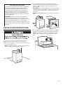
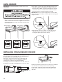
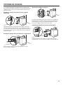
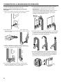
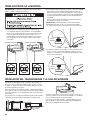
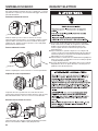
Proper routing of the drain hose avoids damage to your oor
due to water leakage.
Remove drain hose from the washer drum
1. Remove tape from the washer drain port on the back of
the washer.
2. If clamp is not already in place on elbow end of drain hose,
slide it over end as shown.
3. Squeeze clamp with pliers and slide elbow end of drain
hose onto washer drain port and secure with clamp.
4. The washer drain system can be installed using a oor drain,
wall standpipe, oor standpipe, or laundry tub.
CONNECT DRAIN HOSE
5. Place hose into standpipe (shown in picture) or over side
of laundry tub.
IMPORTANT: 114 mm (4.5") of drain hose should be inside
standpipe; do not force excess hose into standpipe or lay
on bottom of laundry tub. Drain hose form must be used.
6. For oor drain installations, you will need to remove the drain
hose form from the end of the drain hose. You may need
additional parts with separate directions. See “Tools and Parts.”
7. The oor drain system requires a siphon break that may be
purchased separately. The siphon break (Part Number 285834)
must be a minimum of 710 mm (28") from the bottom of the
washer. Additional hoses might be needed.
710 mm
(28")
Drain
hose form
114 mm
(4,5")
.
Drain
hose
form

11
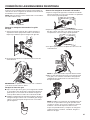
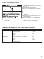
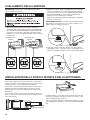
CONNECT INLET HOSES
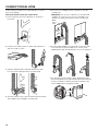
Connect Inlet Hoses to Washer
1. Attach cold water hose to cold water inlet valve marked with
a blue ring. Screw coupling by hand until it is snug.
2.
Attach hot water hose to hot water inlet valve marked with
a red ring. Screw coupling by hand until it is snug.
3.
Use pliers to tighten couplings an additional two-thirds turn.
NOTE: Do not overtighten. Damage to the valve can result.
4.
Turn on water faucets to check for leaks. A small amount
of water may enter washer. It will drain later.
NOTE: Replace inlet hoses after 5 years of use to reduce the
risk of hose failure. Record hose installation or replacement
dates on the hoses for future reference.
Periodically inspect and replace hoses if bulges, kinks, cuts,
wear, or leaks are found.
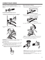
Insert new hose washers (supplied) into each end of the inlet
hoses. Firmly seat the washers in the couplings.
NOTE: Use new hoses supplied with the washer. Do not reuse
old hoses.
Connect Inlet Hoses to Water Faucets
1. Attach hose to hot water faucet. Screw on coupling until
it is seated on washer. Repeat process for cold water.
2.
Use pliers to tighten the couplings an additional two-thirds
turn.
IMPORTANT: Do not overtighten or use tape or sealants on valve
when attaching to faucets or washer. Damage can result.
Clear Water Lines
n Run water through both faucets and inlet hoses, into a laundry
tub, drainpipe, or bucket, to get rid of particles in the water
lines that might clog the inlet valve screens.
n
Check the temperature of the water to make sure that the hot
water hose is connected to the hot water faucet and that the
cold water hose is connected to the cold water faucet.
CouplingWasher

12
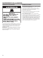
1. Move the washer to its nal location. Place a level on top
edges of washer. Use side seam as a guide to check levelness
of sides. Check levelness of front using lid, as shown. Rock
washer back and forth to make sure all four feet make solid
contact with oor.
LEVEL WASHER
IMPORTANT: Level washer properly to reduce excess noise
and vibration.
Not Level LEVEL Not Level
2.
Use a 9/16" or 14 mm open-end or adjustable wrench to turn
jam nuts clockwise on feet until they are about 13 mm (1/2")
from the washer cabinet. Then turn the leveling foot clockwise
to lower the washer or counterclockwise to raise the washer.
Recheck levelness of washer and repeat as needed.
HELPFUL TIP: You may want to prop up front of washer about
102 mm (4") with a wood block or similar object that will support
weight of washer.
Place level here
Place level here
Jam nut
Jam nut
3. When washer is level, use a 9/16" or 14 mm open-end or
adjustable wrench to turn jam nuts counterclockwise on
leveling feet tightly against washer cabinet.
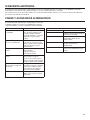
INSTALLING COIN SLIDE AND COIN BOX
The coin slide mechanism, service door lock and key, and coin
box lock and key are not included with some models, but can
be obtained from the usual industry sources.
Remove the service door of the meter case by lifting it up
at the back. Install the money-accepting device. (Refer to
manufacturer’s instructions for proper installation.)
An earthing connection is needed for the coin slide, which can
be made by connecting the available harness to the coin slide.
Install a lock and cam on the meter case service door. Install the
coin vault with lock and key in the meter case opening.
For Free Vend, an OPL kit can be purchased from Whirlpool.
Whirlpool part number W10222023, Greenwald part number
3001-003.
Earthing
connection
Place level here
Place level here
Jam nut
Jam nut

13
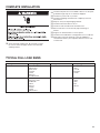
q
Check electrical requirements. Be sure that you have
the correct electrical supply and the recommended
earthing method.
COMPLETE INSTALLATION
q
Check that all parts are now installed. If there is an extra part,
go back through steps to see what was skipped.
q
Check that you have all of your tools.
q
Check that shipping materials were completely removed
from washer.
q
Dispose of/recycle all packaging materials.
q
Check that the water faucets are on.
q
Check for leaks around faucets and inlet hoses.
q
Remove lm from console and any tape remaining on
washer.
q
Plug into an earthed outlet or connect power.
q
Check that circuit breaker is not tripped or fuse is not blown.
q
Start washer using the payment system (if available) to
check that the wash cycle completes without an error code
or water leak.
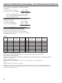
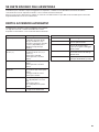
TYPICAL FULL LOAD SIZES
Load Type Loading Suggestion Load Type Loading Suggestion
Mixed Load 3 double sheets
4 pillowcases
6 pair shorts
8 T-shirts
2 shirts
2 blouses
8 handkerchiefs
Heavy Work Clothes 3 pair pants
3 shirts
1 coverall
4 pair jeans
1 overall
Permanent Press 2 double or
1 king size sheet
1 tablecloth
1 dress
1 blouse
2 slacks
3 shirts
2 pillowcases
Knits 3 blouses
4 slacks
6 shirts
4 tops
4 dresses

14
WASHER MAINTENANCE
It is recommended that berglass items not be washed in coin-
operated washers. If these items are washed in the washer, run
the washer through a complete cycle to rinse any residue away
that might be left in the washer.
IMPORTANT: Load detergent, bleach, and fabric softener
before adding clothes and do all of this before starting the
washer as the lid will lock after starting the washer.
Operating Tips
Transporting Your Washer
• Shut off both water faucets. Disconnect and drain water
inlet hoses.
• Disconnect drain from drain system and drain any remaining
water into a pan or bucket. Disconnect drain hose from back
of washer.
• Unplug power cord.
• Place inlet hoses and drain hose inside washer basket.
• Drape power cord over edge and into washer basket.
• Place packing tray from original shipping materials back inside
washer and reuse shipping base to support the motor and tub.
If you do not have original packaging, place heavy blankets
or towels above basket, between the washer top and the tub
ring. Close lid and place tape over lip and down the front of the
washer. Keep lid taped until washer is moved to new location.

15
Your installation may require additional parts. To order, please contact your authorized Commercial Laundry distributor
from whom you purchased your washer or an authorized service company.
You will need the washer model number and serial number. Both numbers can be found on the serial-rating plate located
on the washer.
IF YOU NEED ASSISTANCE
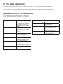
ALTERNATE PARTS & ACCESSORIES
Your installation may require additional parts. To order, please
contact the dealer from whom you purchased your washer or
an authorized service company.
If You Have: You Will Need:
Overhead sewer Standard 76 L (20 gal.) 990 mm
(39") tall drain tub or utility sink,
sump pump and connectors
(available from local plumbing
suppliers)
25 mm (1") standpipe 51 mm (2") diameter to
25 mm (1") diameter Standpipe
Adapter Part Number 3363920
Connector Kit Part Number
285835
Lint clogged drain Drain Protector Part Number
367031 Connector Kit Part
Number 285835
Floor drain system Siphon break, Part Number
285834 Connector Kit (x2) Part
Number 285835 Extension Drain
Hose Part Number 285863
Water faucets beyond
reach of ll hoses
2 longer water ll hoses:
1,8 m (6 ft.) 90° bend hose
Part Number 76314, 3,0 m (10 ft.)
Part Number 350008
Inlet hoses are sold as a pair
in kit W10575888
Accessories
If You Have: You Will Need:
Washer Drip Trays
Part Number 8212526
Cap/Cover-Bleach Dispenser
Part Number W10515386A
Fabric Softener Dispenser Kit
Part Number W10461164A
Main Top Rear Support
W10576550 (2 per kit)

16
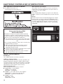
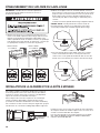
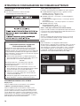
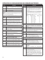
ELECTRONIC CONTROLS SET-UP INSTRUCTIONS
Basic Operation of Commercial Washer
n For additional information, see
www.MaytagCommercialLaundry.com
IMPORTANT
Electrostatic Discharge (ESD)
Sensitive Electronics
ESD problems are present everywhere. ESD may damage
or weaken the electronic control assembly. The new control
assembly may appear to work well after repair is nished, but
failure may occur at a later date due to ESD stress.
n Use an anti-static wrist strap. Connect wrist strap to green
ground connection point or unpainted metal in the washer.
-OR-
Touch your nger repeatedly to a green earth connection point
or unpainted metal in the washer.
n Before removing the part from its package, touch the
anti-static bag to a green earth connection point or
unpainted metal in the washer.
n Avoid touching electronic parts or terminal contacts; handle
electronic control assembly by edges only.
n When repackaging failed electronic control assembly in
anti-static bag, observe above instructions.
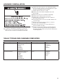
GENERAL USER INFORMATION
Blank Display
This condition indicates the washer is inoperative.
‘0 Minutes’ showing in display
This condition indicates the washer cannot be operated. Coins
dropped or debit inputs during this condition will be stored in
escrow but cannot be used until normal operation is restored by
opening and closing the door. If a door switch fails, it must be
replaced before normal operation can be restored.
Cold Start (initial first use)
Washer is programmed at the factory as follows:
n POWER WASH = 19 min agitation
NORMAL = 9 min agitation
DELICATES = 7 min agitation
n NORMAL = 1 rinse and 2 minutes of rinse agitation
POWER WASH = 4 spray rinses with spin-outs
DELICATES = 3 spray rinses with spin-outs
n NORMAL = $1.50
DELICATES = $1.00
POWER WASH = $2.00
Warm Start (after power failure)
After a delay of up to 8 seconds, the washer is restored to the
portion of the cycle that existed at time of the power failure. To
continue the cycle, press START.
Free Cycles
This is established by setting the cycle price to zero. When this
happens, ‘SELECT CYCLE’ will appear and cycle price will show
0.00.
Display
After the washer has been installed and plugged in, the display
will show ‘SYnC’ for a few seconds, then ‘0 MINUTES’. Once
the washer has been plugged in and the washer lid opened and
closed, the display will show the price. In washers set for free
cycles, the display will ash ‘SELECT CYCLE’, and will display
‘PRICE 0.00’.

17
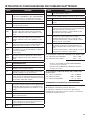
ELECTRONIC CONTROLS SET-UP INSTRUCTIONS
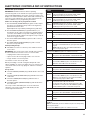
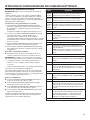
Control Set-up Procedures
IMPORTANT: Read all instructions before operating.
The three key pads on the left side, the top key pad on the right
side, and the digital display are used to set up the controls. The
display can contain 4 numbers and/or letters and a decimal point.
These are used to indicate the set-up codes and related code
values available for use in programming the washer.
How to use the key pads to program the controls
1. The LEFT UPPER (POWER WASH) key pad is used to adjust
the values associated with set-up codes. Pressing the key
pad will increment the value.
Rapid adjustment is possible by holding the key pad down.
2. The LEFT MIDDLE (NORMAL) key pad will advance you
through the set-up codes. Pressing the key pad will advance
you to the next available set-up code. Holding the key pad
down will automatically advance through the set-up codes at
a rate of one (1) per second.
3. The LEFT LOWER (DELICATES) key pad is used to select or
deselect options.
4. The RIGHT UPPER (TEMPERATURE) key pad is used to
decrease set-up code value.
Start Operating Set-Up
n PD Models: Insert access door key, turn, and lift to remove
access door.
IMPORTANT: The console must not be opened unless power is
rst removed from the washer. To access connector AA1:
g
Unplug washer or disconnect power.
g
Open console, disconnect plug on AA1, close console.
g
Plug in washer or reconnect power.
The washer is now in the set-up mode.
Before proceeding, it is worth noting that, despite all of the
options available, an owner can simply choose to uncrate a new
commercial washer, hook it up, plug it in, and have a unit that
operates.
Set-up Codes
n The LEFT MIDDLE (NORMAL) key pad will advance from code
to code.
n The LEFT UPPER (POWER WASH) key pad will increase the
code value.
n The LEFT LOWER (DELICATES) key pad will select or
deselect options.
n The RIGHT UPPER (TEMPERATURE) key pad will decrease
the code value.
The set-up code is indicated by the one or two left-hand
characters. The set-up code value is indicated by the two
or three right-hand characters.
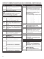
CODE EXPLANATION
6.06
NORMAL
NORMAL Regular Cycle Vend Price - Increase or decrease
between 0 and 200 by pressing the LEFT UPPER or RIGHT
UPPER key pad. Factory preset for 6 coins = $1.50.
6.04
DELICATES
DELICATES Regular Cycle Vend Price - Increase or decrease
between 0 and 200 by pressing the LEFT UPPER or RIGHT
UPPER key pad. Factory preset for 4 coins = $1.00.
6.08
POWERWASH
POWERWASH Regular Cycle Vend Price - Increase or decrease
between 0 and 200 by pressing the LEFT UPPER or RIGHT
UPPER key pad. Factory preset for 8 coins = $2.00.
g Press the LEFT MIDDLE key pad once to advance to next code.
7.00 ADDITIONAL WASH TIME
7.00 This is the number of minutes that can be added to a Wash Cycle.
Choose from 00-05 minutes by pressing the LEFT UPPER key
pad.
g Press the LEFT MIDDLE key pad once to advance to next code.
8.00 ADDITIONAL RINSE TIME
8.00 This is the number of minutes that can be added to a RINSE
Cycle. Choose from 00-05 minutes by pressing the LEFT UPPER
key pad.
NOTE: Additional rinse time only available in defaulted bath
rinses, not in spray rinse option.
g Press the LEFT MIDDLE key pad once to advance to next code.
9.00 CYCLE COUNTER OPTION
This option is either SELECTED ‘ON’ or NOT SELECTED ‘OFF’.
9.00 Not Selected ‘OFF’.
9.0C Selected ‘ON’ and not able to be deselected.
Press the LEFT LOWER key pad 3 consecutive times to select
‘ON’. Once selected ‘ON’ it cannot be deselected.
g Press the LEFT MIDDLE key pad once to advance to next code.
1.00 MONEY COUNTER OPTION
This option is either SELECTED ‘ON’ or NOT SELECTED ‘OFF’.
1.00 Not Selected ‘OFF’.
1.0C Selected ‘ON’.
Press the LEFT LOWER key pad 3 consecutive times to select
‘ON’ and 3 consecutive times to remove (Not Selected ‘OFF’.)
Counter resets by going from ‘OFF’ to ‘ON’.
1.C0 Selected ‘ON’ and not able to be deselected.
To select ‘ON’ and not able to be deselected, rst select ‘ON’,
then within two seconds press the LEFT LOWER key pad twice,
the LEFT UPPER key pad once, and exit the set-up mode.
g Press the LEFT MIDDLE key pad once to advance to next code.
2.00 SPECIAL PRICING OPTION
This option is either SELECTED ‘ON’ or NOT SELECTED ‘OFF’.
2.00 Not Selected ‘OFF’.
2.SP Selected ‘ON’. Press the LEFT LOWER key pad once for this
selection.
If SPECIAL PRICING OPTION is selected, there is access to codes ‘3.’
through ‘9.’.
NOTE: An external battery needs to be added to keep the clock running during
periods of power outages.
g Press the LEFT MIDDLE key pad once to advance to next code.

18
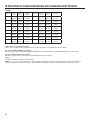
ELECTRONIC CONTROLS SET-UP INSTRUCTIONS
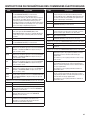
CODE EXPLANATION
OPTIONS TO USE IF SPECIAL PRICING IS SELECTED:
3.06
NORMAL
NORMAL Special Cycle Vend Price - Increase or decrease
between 0 and 200 by pressing the LEFT UPPER or RIGHT
UPPER key pad. Factory preset for 6 coins = $1.50.
3.04
DELICATES
DELICATES Special Cycle Vend Price - Increase or decrease
between 0 and 200 by pressing the LEFT UPPER or RIGHT
UPPER key pad. Factory preset for 4 coins = $1.00.
3.08
POWERWASH
POWERWASH Special Cycle Vend Price - Increase or decrease
between 0 and 200 by pressing the LEFT UPPER or RIGHT
UPPER key pad. Factory preset for 8 coins = $2.00.
g Press the LEFT MIDDLE key pad once to advance to next code.
5.00 TIME-OF-DAY CLOCK, MINUTES
5.00 This is the TIME-OF-DAY CLOCK, minute setting; select between
0 and 59 minutes by pressing the LEFT UPPER or RIGHT UPPER
key pad.
g Press the LEFT MIDDLE key pad once to advance to next code.
6.00 TIME-OF-DAY CLOCK, HOURS
NOTE: Uses military time or 24 hr. clock.
6.00 This is the TIME-OF-DAY CLOCK, hour setting; select between
0 and 23 hours by pressing the LEFT UPPER or RIGHT UPPER
key pad.
g Press the LEFT MIDDLE key pad once to advance to next code.
7.00 SPECIAL PRICE START HOUR
NOTE: Uses military time or 24 hr. clock.
7.00 This is the start hour; select between 0 and 23 hours by pressing
the LEFT UPPER or RIGHT UPPER key pad.
g Press the LEFT MIDDLE key pad once to advance to next code.
8.00 SPECIAL PRICE STOP HOUR
NOTE: Uses military time or 24 hr. clock.
8.00 This is the stop hour; select between 0 and 23 hours by pressing
the LEFT UPPER or RIGHT UPPER key pad.
g Press the LEFT MIDDLE key pad once to advance to next code.
9.00 SPECIAL PRICE DAY
9.10 This represents the day of the week and whether special pricing
is selected for that day. A number followed by ‘0’ indicates no
selection that particular day (9.10). A number followed by an ‘S’
indicates selected for that day (9.1S).
Days of the week (1-7) can be chosen by pressing the LEFT
UPPER key pad. Press the LEFT UPPER key pad once to select
special pricing for each day chosen.
When exiting set-up code ‘9’, the display must show current day
of week:
DISPLAY DAY OF WEEK CODE (selected)
10 Day 1 = Sunday 1S
20 Day 2 = Monday 2S
30 Day 3 = Tuesday 3S
40 Day 4 = Wednesday 4S
50 Day 5 = Thursday 5S
60 Day 6 = Friday 6S
70 Day 7 = Saturday 7S
g Press the LEFT MIDDLE key pad once to advance to next code.
CODE EXPLANATION
A.00 VAULT VIEWING OPTION
This option is either SELECTED ‘ON’ or NOT SELECTED ‘OFF’.
A.00 Not Selected ‘OFF’.
A.SC Selected ‘ON’. Press the LEFT LOWER key pad once for this
selection. When selected, the money and/or cycle counts will be
viewable (depending on what is selected) when the coin box is
removed.
g Press the LEFT MIDDLE key pad once to advance to next code.
b.05 VALUE OF COIN 1
b.05 This represents the value of coin 1 in number of 5% increments of
the larger coin value. 5 x 5% = 25%.
By pressing the LEFT UPPER or RIGHT UPPER key pad, there
is the option of between 1 and 199 for the quantity of 5%
increments.
g Press the LEFT MIDDLE key pad once to advance to next code.
C.20 VALUE OF COIN 2
C.20 This represents the value of coin 2 in number of 5% increments of
the larger coin value. 2 x 5% = 100%.
By pressing the LEFT UPPER or RIGHT UPPER key pad, there
is the option of between 1 and 199 for the quantity of 5%
increments.
g Press the LEFT MIDDLE key pad once to advance to next code.
d.00 COIN SLIDE OPTION
This option is either SELECTED ‘ON’ or NOT SELECTED ‘OFF’.
d.00 Not Selected ‘OFF’.
d.CS Selected ‘ON’. Press the LEFT LOWER key pad 3 consecutive
times for this selection.
When coin slide mode is selected, set ‘b.’ equal to value of slide
in 5% increments. Set step 6 (regular cycle price) and step 3
(special cycle price) to number of slide operations. If the installer
sets up ‘CS’ on a coin drop model, it will not register coins.
g Press the LEFT MIDDLE key pad once to advance to next code.
E.00 ADD COINS OPTION
This option is either SELECTED ‘ON’ or NOT SELECTED ‘OFF’.
This option causes the customer display to show the number of
coins (coin 1) to enter, rather than the monetary amount.
E.00 Not Selected ‘OFF’.
E.AC Selected ‘ON’. Press the LEFT LOWER key pad 3 consecutive
times for this selection.
g Press the LEFT MIDDLE key pad once to advance to next code.
H.00
COOL
COOL Temperature Upgrade Price - Increase or decrease
between 0 and 200 by pressing the LEFT UPPER or RIGHT
UPPER key pad. Factory preset for 1 coins = $0.25.
H.00
WARM
WARM Temperature Upgrade Price -
Increase or decrease
between
0 and 200 by pressing the LEFT UPPER or RIGHT
UPPER key pad. Factory preset for 2 coins = $0.50.
H.00
HOT
HOT Temperature Upgrade Price - Increase or decrease between
0 and 200 by pressing the LEFT UPPER or RIGHT UPPER key
pad. Factory preset for 3 coins = $0.75.
H.00
HEAVY
HEAVY SOIL LEVEL Upgrade Price - Increase or decrease
between 0 and 200 by pressing the LEFT UPPER or RIGHT UPPER
key pad. Factory preset for 1 coins = $0.25.

19
ELECTRONIC CONTROLS SET-UP INSTRUCTIONS
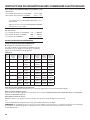
CODE EXPLANATION
H.00
EXTRA
RINSE
EXTRA RINSE Upgrade Price - Increase or decrease between 0
and 200 by pressing the LEFT UPPER or RIGHT UPPER key pad.
Factory preset for 1 coins = $0.25.
g Press the LEFT MIDDLE key pad once to advance to next code.
J.Cd COIN/DEBIT OPTION
J.Cd Both coin & debit selected.
J.C_ Coins selected, debit disabled. Press the LEFT LOWER key pad
3 times for this selection.
J._d Debit Card selected, coins disabled. Press the LEFT LOWER key
pad 3 times for this selection.
J.Ed Enhanced Debit is self-selected when a Generation 2 card reader
is installed in the washer. The Ed option cannot be manually
selected or deselected.
g Press the LEFT MIDDLE key pad once to advance to next code.
L.00 PRICE SUPPRESSION OPTION
This option causes the customer display to show ‘ADD’ or
‘AVAILABLE’ rather than the amount of money to add. (Used
mainly in debit installations.)
L.00 Not Selected ‘OFF’.
L.PS Selected ‘ON’. Press the LEFT LOWER key pad once for this
selection.
g Press the LEFT MIDDLE key pad once to advance to next code.
n. CE CLEAR ESCROW OPTION
When selected, money held in escrow for 30 minutes without
further escrow or cycle activity will be cleared.
n. CE Selected ‘ON’.
n. 00 Not selected ‘OFF’. Press the LEFT LOWER key pad once to
deselect this selection.
g Press the LEFT MIDDLE key pad once to advance to next code.
U.00 COIN (HUNDREDTH) INCREMENT OFFSET
U.00 For use with card reader applications only.
g Press the LEFT MIDDLE key pad once to advance to next code.
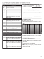
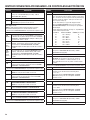
A3.02 NORMAL Cycle Settings. Allows the owner to select the cycle
default options of Water Temperature, Soil Level, and Extra Rinse.
See Table 1 for specic settings. Normal is set to 02 from the
factory.
A4.00 DELICATES Cycle Settings. Allows the owner to select the cycle
default options of Water Temperature, Soil Level, and Extra Rinse.
See Table 1 for specic settings. Delicates is set to 00 from the
factory.
A5.OF POWERWASH Cycle Settings. Allows the owner to select the
cycle default options of Water Temperature, Soil Level, and Extra
Rinse.
See Table 1 for specic settings. Powerwash is set to 0F from the
factory.
If cycle counter (9.0C) is selected, the following is true:
1 xx Number of cycles in THOUSANDS. 1 02 = 2,000
2xxx Number of cycles in ONES. 2225 = 225
TOTAL CYCLES = 2,225
This is “VIEW ONLY” and cannot be cleared.
Press the LOWER MIDDLE key pad once to advance
to next code.
If money counter (1.0C or 1.C0) is selected, the following is
true:
3 xx Number in THOUSANDS. 3 01 = $1,000.00
4xxx Number in ONES. 4600 = $ 600.00
5 xx Number of HUNDRETHS. 5 75 = $ 00.75
TOTAL = $1,600.75
END OF SET-UP PROCEDURES
EXIT FROM SET-UP MODE
n PD Models: Reinstall access door.
If preferred, just wait through 2 minutes of inactivity. All settings
will be saved and the display will revert to Select Cycle screen.
A3, A4,
or A5
Extra
Rinse
Soil
Level
Wash
Temp
A3, A4,
or A5
Extra
Rinse
Soil
Level
Wash
Temp
00 Off Off Cold 08 On Off Cold
01 Off Off Cool 09 On Off Cool
02 Off Off Warm 0A On Off Warm
03 Off Off Hot 0b On Off Hot
04 Off On Cold 0c On On Cold
05 Off On Cool 0d On On Cool
06 Off On Warm 0E On On Warm
07 Off On Hot 0F On On Hot
Table 1
Technician Service Access Code
This method is only available on washers set to free vend (6 00).
To enter service mode:
Press the LEFT UPPER, RIGHT LOWER, RIGHT UPPER, and
LEFT LOWER key pads within 10 seconds.
To exit service mode:
Wait 2 minutes without touching any key pads (without diagnostic
modes running)
or
Power down the washer, then reapply power
NOTE: If a service cycle is in progress upon exiting service mode,
the cycle will complete normally with cycle status information
displayed. The display will resume normal customer operation
mode when the cycle ends.

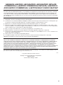
20
MAYTAG
®
COMMERCIAL WASHER, DRYER, STACKED DRYER/
DRYER, COMMERCIAL STACK LAUNDRY, AND MULTI-LOAD COIN
OPERATED COMMERCIAL WASHERS AND DRYERS WARRANTY
LIMITED WARRANTY ON PARTS
For the rst ve years from the date of purchase, when this commercial appliance is installed, maintained and operated according
to instructions attached to or furnished with the product, Maytag brand of Whirlpool Corporation (thereafter “Maytag”) will pay for
factory specied parts or original equipment manufacturer parts to correct defects in materials or workmanship. Proof of original
purchase date is required to obtain service under this warranty.
ITEMS MAYTAG WILL NOT PAY FOR
1. All other costs including labor, transportation, or custom duties.
2. Service calls to correct the installation of your commercial appliance, to instruct you how to use your commercial appliance, to
replace or repair fuses, or to correct external wiring or plumbing.
3. Repairs when your commercial appliance is used for other than normal, commercial use.
4. Damage resulting from improper handling of product during delivery, theft, accident, alteration, misuse, abuse, re, ood, acts
of God, improper installation, installation not in accordance with local electrical or plumbing codes, or use of products not
approved by Maytag.
5. Pickup and Delivery. This commercial appliance is designed to be repaired on location.
6. Repairs to parts or systems resulting from unauthorized modications made to the commercial appliance.
7. The removal and reinstallation of your commercial appliance if it is installed in an inaccessible location or is not installed in
accordance with published installation instructions.
8. Chemical damage is excluded from all warranty coverage.
9. Changes to the building, room, or location needed in order to make the commercial appliance operate correctly.
10. Repairs made by a non-Whirlpool authorized service technician.
DISCLAIMER OF IMPLIED WARRANTIES; LIMITATIONS OF REMEDIES
CUSTOMER’S SOLE AND EXCLUSIVE REMEDY UNDER THIS LIMITED WARRANTY SHALL BE PRODUCT REPAIR AS PROVIDED
HEREIN. IMPLIED WARRANTIES, INCLUDING WARRANTIES OF MERCHANTABILITY OR FITNESS FOR A PARTICULAR
PURPOSE, ARE LIMITED TO ONE YEAR OR THE SHORTEST PERIOD ALLOWED BY LAW. WHIRLPOOL SHALL NOT BE LIABLE
FOR INCIDENTAL OR CONSEQUENTIAL DAMAGES. SOME STATES AND PROVINCES DO NOT ALLOW THE EXCLUSION OR
LIMITATION OF INCIDENTAL OR CONSEQUENTIAL DAMAGES, OR LIMITATIONS ON THE DURATION OF IMPLIED WARRANTIES
OF MERCHANTABILITY OR FITNESS, SO THESE EXCLUSIONS OR LIMITATIONS MAY NOT APPLY TO YOU. THIS WARRANTY
GIVES YOU SPECIFIC LEGAL RIGHTS AND YOU MAY ALSO HAVE OTHER RIGHTS, WHICH VARY FROM STATE TO STATE OR
PROVINCE TO PROVINCE.
If you need service, please contact your authorized Maytag
®
Commercial Laundry distributor. To locate your authorized Maytag
®
Commercial Laundry distributor, or for web inquiries, visit www.MaytagCommercialLaundry.com.
For written correspondence:
Maytag
®
Commercial Laundry Service Department
2000 M-63 North
Benton Harbor, Michigan 49022 USA
1/11
La page est en cours de chargement...
La page est en cours de chargement...
La page est en cours de chargement...
La page est en cours de chargement...
La page est en cours de chargement...
La page est en cours de chargement...
La page est en cours de chargement...
La page est en cours de chargement...
La page est en cours de chargement...
La page est en cours de chargement...
La page est en cours de chargement...
La page est en cours de chargement...
La page est en cours de chargement...
La page est en cours de chargement...
La page est en cours de chargement...
La page est en cours de chargement...
La page est en cours de chargement...
La page est en cours de chargement...
La page est en cours de chargement...
La page est en cours de chargement...
La page est en cours de chargement...
La page est en cours de chargement...
La page est en cours de chargement...
La page est en cours de chargement...
La page est en cours de chargement...
La page est en cours de chargement...
La page est en cours de chargement...
La page est en cours de chargement...
La page est en cours de chargement...
La page est en cours de chargement...
La page est en cours de chargement...
La page est en cours de chargement...
La page est en cours de chargement...
La page est en cours de chargement...
La page est en cours de chargement...
La page est en cours de chargement...
La page est en cours de chargement...
La page est en cours de chargement...
La page est en cours de chargement...
La page est en cours de chargement...
La page est en cours de chargement...
La page est en cours de chargement...
La page est en cours de chargement...
La page est en cours de chargement...
La page est en cours de chargement...
La page est en cours de chargement...
La page est en cours de chargement...
La page est en cours de chargement...
La page est en cours de chargement...
La page est en cours de chargement...
La page est en cours de chargement...
La page est en cours de chargement...
La page est en cours de chargement...
La page est en cours de chargement...
La page est en cours de chargement...
La page est en cours de chargement...
-
 1
1
-
 2
2
-
 3
3
-
 4
4
-
 5
5
-
 6
6
-
 7
7
-
 8
8
-
 9
9
-
 10
10
-
 11
11
-
 12
12
-
 13
13
-
 14
14
-
 15
15
-
 16
16
-
 17
17
-
 18
18
-
 19
19
-
 20
20
-
 21
21
-
 22
22
-
 23
23
-
 24
24
-
 25
25
-
 26
26
-
 27
27
-
 28
28
-
 29
29
-
 30
30
-
 31
31
-
 32
32
-
 33
33
-
 34
34
-
 35
35
-
 36
36
-
 37
37
-
 38
38
-
 39
39
-
 40
40
-
 41
41
-
 42
42
-
 43
43
-
 44
44
-
 45
45
-
 46
46
-
 47
47
-
 48
48
-
 49
49
-
 50
50
-
 51
51
-
 52
52
-
 53
53
-
 54
54
-
 55
55
-
 56
56
-
 57
57
-
 58
58
-
 59
59
-
 60
60
-
 61
61
-
 62
62
-
 63
63
-
 64
64
-
 65
65
-
 66
66
-
 67
67
-
 68
68
-
 69
69
-
 70
70
-
 71
71
-
 72
72
-
 73
73
-
 74
74
-
 75
75
-
 76
76


Maytag MVW18MN Installation Instructions Manual
- Taper
- Installation Instructions Manual
dans d''autres langues
- italiano: Maytag MVW18MN
- English: Maytag MVW18MN
- español: Maytag MVW18MN