Rackmount Solutions XRT Series Manuel utilisateur
- Catégorie
- Alimentations sans interruption (UPS)
- Taper
- Manuel utilisateur


1

2
XRT Series User’s Manual
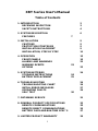
Table of Contents
1. INTRODUCTION 2
RECEIVING INSPECTION 3
SAFETY INSTRUCTIONS 4
2. SYSTEM DESCRIPTION 6
FEATURES 7
3. INSTALLATION 9
CAUTIONS 9
PROTECTION STRATEGIES 9
INSTALLATION PLACEMENT 9
INSTALLATION, STEP BY STEP 11
4. OPERATION 15
FRONT PANELS 15
ALARMS AND WARNINGS 22
WARNING EVENTS 23
OPTIONS 23
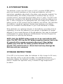
5. SYSTEM BATTERIES 24
STORAGE INSTRUCTIONS 24
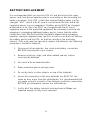
BATTERY REPLACEMENT 25
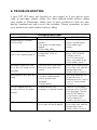
6. TROUBLESHOOTING 26
TROUBLESHOOTING CHART 26
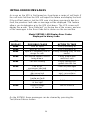
INITIAL ERROR MESSAGES 27
OPERATING FAULTS 29
SELF TEST 30
7. OBTAINING SERVICE 31
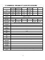
8. GENERAL PRODUCT SPECIFICATIONS 33
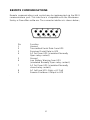
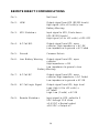
REMOTE COMMUNICATIONS 35
REMOTE DIRECT COMMUNICATIONS 35
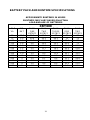
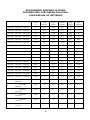
BATTERY PACK AND RUN TIME SPEC’S 37
9. LIMITED PRODUCT WARRANTY 39

3
1. INTRODUCTION
Thank you for purchasing the Minuteman XRT series of Uninterruptible
Power Supplies. It has been designed and manufactured to provide many
years of trouble free service.
IMPORTANT!
Please read this manual before installing your UPS as it provides the
information to correctly set up your system for the maximum safety and
performance. Included is information on how the UPS functions to protect
your equipment from power line induced spikes, RFI and EMI, blackouts,
brownouts, sags and over-voltage conditions.
Included is information on customer support and factory service if it is
required. If you experience a problem with the UPS please refer to the
Troubleshooting guide in this manual to correct the problem or collect
enough information so that the Minuteman technical support department
can rapidly assist you.
Para Systems Life Support Policy
As a general policy, Para Systems Inc. does not recommend the use of any of its
products in life support applications where failure or malfunction of the Para Systems
product can be reasonably expected to cause failure of the life support device or to
significantly affect its safety or effectiveness. Para Systems does not recommend the
use of any of its products in direct patient care. Para Systems will not knowingly sell
its products for use in such applications unless it receives in writing assurances
satisfactory to Para Systems that (a) the risks of injury or damage have been
minimized, (b) the customer assumes all such risks, and (c) the liability of Para Systems
Inc. is adequately protected under the circumstances.
Examples of devices considered to be life support devices are neonatal oxygen
analyzers, nerve stimulators (whether used for anesthesia, pain relief, or other
purposes), auto transfusion devices, blood pumps, defibrillators, arrhythmia detectors
and alarms, pacemakers, hemodialysis systems, peritoneal dialysis systems, neonatal
ventilator incubators, ventilators for both adults and infants, anesthesia ventilators, and
infusion pumps as well as any other devices designated as “critical” by the United
States FDA.
Hospital grade wiring devices and leakage current may be ordered as options on many
Para Systems UPS systems. Para Systems does not claim that units with this
modification are certified or listed as Hospital Grade by Para Systems or any other

4
organization. Therefore, these units do not meet the requirements for use in direct
patient care.

5
RECEIVING INSPECTION
After removing your Minuteman XRT UPS from its carton, it should be inspected for
damage that may have occurred in shipping. Immediately notify the carrier and place of
purchase if any damage is found. Warranty claims for damage caused by the carrier
will not be honored.
PLEASE SAVE THE PACKING MATERIALS!
The packing materials that your UPS was shipped in are carefully designed to minimize
any shipping damage. In the unlikely case that the UPS needs to be returned to
Minuteman, please use the original packing material. Since Minuteman is not responsible
for shipping damage incurred when the system is returned, the original packing material
is inexpensive insurance.
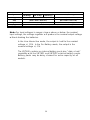
Note: This equipment has been tested and found to comply with the limits for a Class A
digital device, pursuant to part 15 of the FCC rules. These limits are designed to provide
reasonable protection against harmful interference when the equipment is operated in a
commercial environment. This equipment generates, uses, and can radiate radio
frequency energy and, if not installed and used in accordance with the instruction
manual, may cause harmful interference to radio communications. Operation of this
equipment in a residential area is likely to cause harmful interference, in which case the
user will be required to correct the interference at his own expense.
This digital apparatus does not exceed the Class A limits for radio noise emissions from
digital apparatus set out in the Radio Interference Regulations of the Canadian
Department of Communications.
Le présent appareil numérique n’emit pas de bruits radioélectriques dépassant les
limites applicables aux appareils numérique de la Class A prescrites dans le Règlement
sur le brouillage radioélectrique édicte par le ministère dès Communications du Canada.
Shielded communications cables
must be used with this equipment
RADIO FREQUENCY INTERFERENCE
Warning: Changes or modifications to this unit not expressly approved by the party
responsible for compliance could void the users authority to operate this equipment.

6
IMPORTANT SAFETY INSTRUCTIONS
SAVE THESE INSTRUCTIONS
THIS MANUAL CONTAINS IMPORTANT
SAFETY INSTRUCTIONS;
Read this manual carefully before operating the UPS. All instructions and
warnings should be followed during installation, operation and
maintenance of the UPS.
CAUTION: RISK OF ELECTRICAL SHOCK. HAZARDOUS LIVE PARTS
INSIDE THIS POWER SUPPLY ARE ENERGIZED FROM THE
BATTERY SUPPLY EVEN WHEN THE INPUT AC POWER IS
DISCONNECTED.
CAUTION: A BATTERY CAN PRESENT A RISK OF ELECTRICAL
SHOCK, OR BURN FROM HIGH SHORT-CIRCUIT CURRENT.
OBSERVE PROPER PRECAUTIONS.
CAUTION: WHEN REPLACING BATTERIES USE THE SAME NUMBER
AND TYPE OF SEALED LEAD-ACID BATTERIES.
CAUTION: PROPER DISPOSAL OF BATTERIES IS REQUIRED.
REFER TO YOUR LOCAL CODES FOR DISPOSAL REQUIREMENTS.
CAUTION: AVOID INSTALLING THE UNINTERRUPTIBLE POWER
SUPPLY (UPS) IN LOCATIONS WHERE THERE IS WATER OR
EXCESSIVE HUMIDITY.
CAUTION: CONNECT THE UNINTERRUPTIBLE POWER SUPPLY TO A
TWO POLE, THREE WIRE GROUNDING MAINS RECEPTACLE. THE
RECEPTACLE MUST BE CONNECTED TO APPROPRIATE BRANCH
PROTECTION (FUSE OR CIRCUIT BREAKER). CONNECTION TO ANY
OTHER TYPE OF RECEPTACLE MAY RESULT IN A SHOCK HAZARD
AND MAY VIOLATE LOCAL ELECTRICAL CODES.
CAUTION: DO NOT ALLOW WATER OR ANY FOREIGN OBJECT TO
GET INSIDE THE UNINTERRUPTIBLE POWER SUPPLY. DO NOT PUT
OBJECTS CONTAINING LIQUIDS ON OR NEAR THE UNIT.

7
INSTRUCTIONS IMPORTANTES
CONCERNANT LA SÉCURITÉ
CONSERVER CES INSTRUCTIONS.
CETTE NOTICE CONTIENT DES INSTRUCTIONS
IMPORTANTES CONCERNANT LA SÉCURITÉ.
ATTENTION: RISQUE DE CHOC ÉLECTRONIQUE. CE BLOC
D’ALIMENTATION COMPORTE DES PIECES SOUS TENSION
DANGEREUSE ALIMENTÉES PAR LES PILES MEME LORSQU’IL EST
DÉBRANCHÉ DU SECTEUR.
ATTENTION: UNE BATTERIE PEUT PRÉSENTER UN RISQUE DE
CHOC ÉLECTRIQUE, OU DE BRULURE PAR TRANSFERT
D’ENERGIE. SUIVRE LES PRÉCAUTIONS QUI S’IMPOSENT.
ATTENTION: POUR LE REMPLACEMENT, UTILISER LE MEME
NOMBRE DE BATTERIES DU MODÉLE LEAD-ACID SCELLÉES.
ATTENTION: L’EMINATION DES BATTERIES EST RÈGLEMENTÉE.
CONSULTER LES CODES LOCAUX À CET EFFET.
ATTENTION: LA SORCE D’ALIMENTATION PERMANENTE (UPS)
DANS UNE PRISE DE COURANT À 3 DÉRIVATIONS (DEUX POLES ET
LA TERRE). CETTE PRISE DOIT ÊTRE MUNIE D’UNE PROTECTION
ADÉQUATE (FUSIBLE OU COUPE-CIRCUIT). LE BRANCHEMENT
DANS TOUT AUTRE GENRE DE PRISE POURRÎT ENTRAÎNER UN
RISQUE D’ÉLECTROCUTION ET PEUT CONSTITUER UNE
INFRACTION À LA RÉGLEMENTATION LOCALE CONCERNANT LES
INSTALLATIONS ÉLECTRIQUES.
ATTENTION: NE PAS INSTALLER LA SOURCE D’ALIMENTATION
PERMANENTE (UPS) DANS UN ENDROIT OÙ IL Y A DE L’EAU OU
UNE HUMIDITÉ EXCESSIVE.
ATTENTION: NE PAS LAISSER DE L’EAU OU TOUT OBJET
PÉNÉTRER DANS LA SOURCE D’ALIMENTATION PERMANENTE
(UPS). NE PAS PLACER DE RÉCIPIENTS CONTENANT UN LIQUIDE
SUR CET APPAREIL, NI À PROXIMITÉ DE CELUI-CI.

8
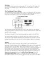
2. SYSTEM DESCRIPTION
The XRT series of Uninterruptible power supplies are based on an
advanced true sinewave power system that filters and protects the
electronic equipment from all types of power line problems. The various
models provide from 600 VA to 2000 VA of power for voltage ranges of
120 VAC, 208 VAC and 240 VAC single phase 60 Hz. units, and 220
VAC through 240 VAC 50 Hz. units. At all power levels and voltage
ranges the load is protected against AC line spikes, surges, dropouts,
brownouts and blackouts. All 60 Hertz models include electrical isolation
from the power line to the AC load. During operation, all of the critical
parameters are continuously monitored. The parameters may be
monitored at the UPS with an LED display on the XRT600, or with a
sophisticated LCD display that contains 32 characters on the XRT1000
and larger units. In all models the communications port can be used with
the Minuteman Sentry or PowerMon software to report all of the critical
parameters as well as controlling the UPS’s functions via remote control.
Built in is the provision for a remote master Output Power OFF switch so
that a user-supplied power down switch or relay can immediately shut off
the output power.
The XRT series of UPS’s are “Line-Interactive”. That is, during normal
operation from the AC line, the line AC is passed through an isolation
transformer
*
and filtering system that provides the maximum efficiency,
safety and reliability. During normal AC operation, the incoming line
voltage is continuously monitored and automatic correction is made for
under-voltage or over-voltage conditions. This provides AC line correction
for a range of 75% to 116% of the nominal line voltage. When these
limits are exceeded, or if the line frequency varies more than plus or
minus 3 Hertz, the unit automatically switches to battery power until
normal AC is restored. In normal operation the battery is continuously
charged so that full battery power is always available.
*
Isolation transformer is on the 60 Hz. units only.

9
FEATURES
Extended Battery Run Time
All models of the XRT series may add multiple optional external XRTBP
battery packs to extend the time that the units can provide power. UPS
de-rating is not required for the additional battery packs. The XRT600
model contains an internal battery, whereas the higher power models
require at least one XRTBP battery pack.
RFI/EMI Suppression
The design features, not only the standard input line filtering, but
contains a specially manufactured transformer
*
that shields the output
from line and inverter spikes resulting from capacitive coupling between
windings. This double protection insures that interference and spikes
cannot get to your equipment, and conversely your equipment cannot
transmit spikes to other equipment on the power line.
No Power Factor De-rating
The XRT series of UPS’s automatically support power factors in the
range of 0.6 to 1.0. This means that no de-rating is required for high
power factors since the unit is capable of supplying full rated power
(instantaneous watts) in either the ON-LINE or On-Battery conditions.
Enhanced Battery Management
To maintain the service life of the battery, the XRT provides various
features. During normal on-line functions the XRT continuously monitors
the battery voltage and keeps the battery at full charge via an intelligent
battery charger built into the unit. The battery’s condition is monitored at
all times, and if a low battery condition is detected, the condition is
reported to the front panel and to the serial communications port. If a low
battery condition is detected, the unit will continue to function on the AC
line. While the unit is on-line, the external battery pack(s) may be
replaced without disruption to the output power. In the XRT1000,
XRT1500 and XRT2000 units, the battery charge condition is reported by
the battery voltage on the LCD display screen, whereas in the XRT600
unit the battery charge condition is reported by LED’s on the front panel.
Remote Communication and Control
Built into the XRT series is a Minuteman standard RS-232
communications port. With the Minuteman Power Management software,
2-way communications can be maintained with a remote computer. All
pertinent data about the UPS can be transmitted to the computer, and

10
commands from the computer can control the UPS. The interface also
allows a single switch to control the output power from the UPS so that a
user-supplied Output Power Off switch or relay can immediately remove
power from the load, or restore power once the problem has been
corrected. See Remote Communications chapter for details of the
communications port.
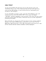
Built in Self Test
To insure the functionality of the UPS, there are four built-in self tests.
The first is when the unit is switched on, a self test is run to insure the
operation of the backup mode, the condition of the battery and the
inverter circuit. This test takes about 10 seconds. Pressing the Test
button, or selecting the Quick Test command from the LCD menu will run
the built-in self test, verifying the operation of the UPS. The third test
mode runs a self test every 14 days to insure the UPS is always ready to
respond to a power problem. The fourth test is the Test to Low Battery
Warning and verifies the condition of the battery system by switching to
inverter power until the battery reaches the Low Battery Warning
condition and then switching back to the ON-LINE mode. During the
“Test to Low Battery”, you may monitor all of the status values and
terminate the test at any time.
The XRT1000 through XRT2000 units have a 32 character LCD display,
three push buttons, and the Power On and DC Start switches.
The Power and DC Start switch operate the same as the XRT600.
The LCD display will step you through all of the functions of the UPS.
The top line of the display indicates the parameter and function, and the
bottom line displays the function of the three buttons below the display.

11
3. INSTALLATION
CAUTION: Do not connect a laser printer to the UPS along with other
computer equipment unless the UPS is rated at 2000 VA or higher. A
laser printer periodically draws significantly more power than when idle,
and may overload the UPS. Verify that the UPS can support the loads
when the printer is in full operation (printing).
PROTECTION STRATEGIES
Minuteman UPS’s provide high quality protection from AC input power
line disturbances to your equipment. However, there are other potential
entry points for damaging surges in information systems. These include
serial ports (RS232, RS422, RS485, etc.), parallel ports (especially
printers not connected to the UPS), telephone lines and network
connections. These other entries must be considered in developing a
comprehensive system protection strategy. Contact your dealer or
Minuteman for information on a complete set of related products
designed to accomplish total system protection. There are some
guidelines listed below that will help in your installation, whether or not
secondary protection is available.
Verify that all electrical outlets are properly grounded.
Do not connect the UPS and protected equipment to the same electrical
service branch that heavy motor loads like air conditioners, copiers,
refrigerators, and heavy electrical machinery are on. Plug all power
protection and protected equipment into the same branch where
possible.
Follow the next steps to install your UPS.
INSTALLATION PLACEMENT
Select the location of the UPS and optional battery pack(s) with care and
use the following precautions:
Select a location that provides unrestricted air flow. It is important to
leave at least 2 inches of space between any object and the sides of the
UPS.

12
Do not place anything on the top of the UPS.
Avoid locations near heating devices.
Avoid locations near water or excessive humidity.
Do not expose the UPS to direct sunlight.
Route power cords where they cannot be walked on or
damaged, or surrounded by other power cords or
communication cables.
Use common sense about placing the UPS where it
cannot be accidentally bumped or turned over.
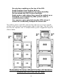
The battery packs and UPS unit must be placed on a level, smooth
surface and cannot be stacked more than 4 units high. The UPS unit
must be the topmost unit. A multiple battery pack suggested layout is
shown below:
Remember to leave at least 2 inches of clearance
around the UPS unit for air flow.

13
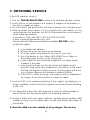
INSTALLATION, STEP BY STEP
1. Insure UPS Power switch is OFF. Place the optional XRTBP
battery pack(s), if used, and XRT UPS in its final location.
2. When installing the XRT1000 and above UPS’s or the XRT600
with optional battery pack(s):
a) Remove the self stick protective strip from the rear of the XRT600
(not required on XRT1000 , 1500, and 2000), and from the optional
battery pack cable.
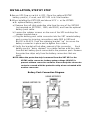
b) Loosen the retainer screws on the rear of the UPS and drop the
retainer bracket down.
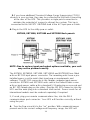
c) Plug the battery pack cable connector into the XRT remote battery
pack connector insuring connections mate RED to RED and
BLACK to BLACK. Push the retaining bracket “up” to secure the
battery connector in place and re-tighten the screws.
d) Verify the bracket will not allow removal of the connector. Each
battery pack is “daisy chained” in a similar fashion with the cable
from the last battery pack connected to the previous pack. Remove
the protective strips only from the battery connectors that are
used.
NOTE: When the protective strip is removed from the XRT UPS or the
XRTBP cable connector, battery system voltage (48 VDC) is
present at these connector contacts. Please keep the connector
contacts covered with the protective strip when not mated with
another connector.
Battery Pack Connection Diagram

14
3. If you have additional Transient Voltage Surge Suppression (TVSS)
devices in your system, they may be connected to the Earth Ground lug
at the rear of the UPS. This provides a single point connection to
minimize the potential of surges to disrupt the system. This lug is
connected to the SAFETY GROUND lead in the AC input power cable.
4. Plug in the UPS to the utility power outlet.
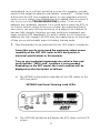
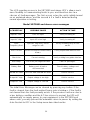
XRT600, XRT1000, XRT1500 and XRT2000 Back panels
NOTE: Due to various input and output options available, your unit
may not be pictured exactly.
The XRT600, XRT600/2, XRT1000, XRT1000/2 and XRT2000/2 are fitted
with an IEC 320 input power connector. The remaining units have a pre-
installed power cord to match their input power requirements and
voltages. The IEC 320 connector is the familiar computer input power
connector. XRT600 and XRT1000 units sold in the United States come
with an input power cable with a standard 5-15 male plug on one end and
an IEC 320 female plug on the other. Plug the IEC 320 connector into the
UPS and the male plug into a standard wall socket. Power cords for all
international models must be ordered separately if required.
5, If used, plug your remote communications line, into the DB-9
communications port connector. Your UPS will function correctly without
using the port.
6. Turn the Power switch to the “on” position. With commercial power
present and in the correct voltage and frequency range, the UPS will

15
automatically run a self test and at the successful completion, provide
power to the output receptacles and indicate “normal AC”. Certain faults
will prevent the UPS from supplying power to your equipment and will
cause an error status to be displayed and an audible alarm to sound. If
this occurs see the TROUBLESHOOTING section. To insure the
batteries are completely charged, it is a good idea to leave the UPS on
for 8 hours before using it to run your system. We understand that in
most cases you may not have the luxury of waiting for the batteries to
become fully charged, therefore you may install your equipment and
begin using the UPS immediately. If a power failure occurs before the
batteries are fully charged, the UPS may not supply power for the length
of time you would normally expect in battery backup mode.
7. Plug all equipment to be protected into the UPS output receptacles.
Insure that you do not exceed the maximum output power
capability of the XRT UPS (refer to UPS back panel or
electrical specifications in this manual).
Turn on your protected equipment one unit at a time and
verify that the “100% Load” condition is not exceeded.
Depending on the XRT model, the Load condition will be
displayed on the front panel as follows:
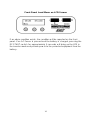
a) The XRT600 will provide an indication of the UPS status on the
LED front panel.
XRT600 Front Panel Showing Load LED’s
b) The XRT1000 and above will display the UPS status on the LCD
screen.

16
Front Panel Load Menu on LCD Screen
If an alarm condition exists, the condition will be reported on the front
panel. If no AC Power is present and the battery is charged, pressing the
DC START switch for approximately 5 seconds will bring up the UPS in
the inverter mode and provide power to the protected equipment from the
battery.

17
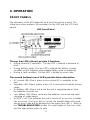
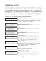
4. OPERATION
FRONT PANELS
The operation of the UPS depends on which front panel is used. The
following section explains the operation for the LED and the LCD front
panels.
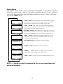
LED Front Panel
The top four LED’s (Green) provide 3 functions.
• During normal AC operation: The top LED’s indicate a measure of
load.
• During battery mode: The top LED’s indicate the battery charge
condition which indicates approximate battery power remaining.
• During a fault condition: The top LED’s display an error code.
The second (bottom) row of LED’s provide status information.
• AC normal LED: Glows green when normal AC is available to the
unit.
• Regulator LED: Glows yellow when AC is present but outside normal
range.
• On battery LED: Glows red when the unit is supplying power from
the batteries (Inverter on).
• Low battery LED: Glows red when the batteries are weak and need
charging or replacement.
• All LED’s off: This indicates the unit is turned off or an error condition
has occurred. If an error has occurred, the internal alarm will sound
and an error code will be displayed on the upper four LED’s. Refer to
the TROUBLESHOOTING section for a description of the error code
and the appropriate action to take.

18
Switches
The Power switch turns the unit on and off. To start the UPS when AC
power is not available, press and hold the DC Start button for about 5
seconds.
The Test/Alarm Silence Button
The Test/Alarm Silence button allows you to run the quick self test when
the UPS is in the normal mode. If an error was detected and you wish to
reset the error display, press the Test/Alarm Silence button.
LCD FRONT PANEL
The XRT1000 through XRT2000 units have a 32 character LCD display,
three push buttons, and the Power On and DC Start switches. (Both 120
and 220 VAC versions)
The Power On and DC Start switch operate the same as the XRT600.
The LCD display will step you through all of the functions of the UPS.
The top line of the display indicates the parameter and function, and the
bottom line displays the function of the three buttons below the display.
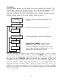
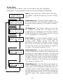
Startup
When the unit is first turned on, the self test is executed and the
message “Startup Diagnostics” is displayed. After successful completion
of the self test, the message “MINUTEMAN Model XRTxxxx” will be
displayed for 5 seconds. The “On-Line xxx% Load” menu then appears. If
the self test was not successful, or if an error event occurred the last
time the UPS was powered on, then the message “Error Detected” will
be shown on the top line of the display and the actual error message is
shown on the second line (see the Initial Error Message list in the
TROUBLESHOOTING section). Pressing any button will clear the
message and allow the unit to power up and show one of two messages.

19
If the unit is being powered from the AC line, the percentage of actual
load power available will be shown by the “ON-LINE xxx% Load”
message. Otherwise, if the unit is being powered from the battery,
“BACKUP xx.xV BAT” message is displayed. In either case, you may
press the button under the “MENU” selection to step to the STATUS
menu.
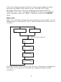
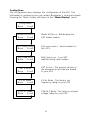
Menu Flow
Note: The “road-map” through the menu system is shown below. In each
individual menu, pressing the “menu” button will take you to the next set
of menus.
The Mode Display will be shown after the unit’s first power up diagnostics
have been run, or when it is selected by stepping through the menu
selections.
ONLINE 50% Load
Menu
BACKUP 52.3V
Bat
Status Menu
Menu
Scroll
Test Menu
Menu Scroll
Menu Selection Sequence
Setup Menu
Menu Scroll
Config Menu
Menu Scroll
La page est en cours de chargement...
La page est en cours de chargement...
La page est en cours de chargement...
La page est en cours de chargement...
La page est en cours de chargement...
La page est en cours de chargement...
La page est en cours de chargement...
La page est en cours de chargement...
La page est en cours de chargement...
La page est en cours de chargement...
La page est en cours de chargement...
La page est en cours de chargement...
La page est en cours de chargement...
La page est en cours de chargement...
La page est en cours de chargement...
La page est en cours de chargement...
La page est en cours de chargement...
La page est en cours de chargement...
La page est en cours de chargement...
La page est en cours de chargement...
La page est en cours de chargement...
La page est en cours de chargement...
La page est en cours de chargement...
-
 1
1
-
 2
2
-
 3
3
-
 4
4
-
 5
5
-
 6
6
-
 7
7
-
 8
8
-
 9
9
-
 10
10
-
 11
11
-
 12
12
-
 13
13
-
 14
14
-
 15
15
-
 16
16
-
 17
17
-
 18
18
-
 19
19
-
 20
20
-
 21
21
-
 22
22
-
 23
23
-
 24
24
-
 25
25
-
 26
26
-
 27
27
-
 28
28
-
 29
29
-
 30
30
-
 31
31
-
 32
32
-
 33
33
-
 34
34
-
 35
35
-
 36
36
-
 37
37
-
 38
38
-
 39
39
-
 40
40
-
 41
41
-
 42
42
-
 43
43


Rackmount Solutions XRT Series Manuel utilisateur
- Catégorie
- Alimentations sans interruption (UPS)
- Taper
- Manuel utilisateur
dans d''autres langues
Autres documents
-
APC 650 Manuel utilisateur
-
APC BP1000 Fiche technique
-
Tripp Lite Single-Phase SmartOnline UPS Le manuel du propriétaire
-
Tripp Lite Single-Phase Online Rack UPS Le manuel du propriétaire
-
-
-
-
-
-
Tripp Lite SmartPro 2U Rackmount UPS Manuel utilisateur