WIKA TC10-L tag:model:TR10-L Mode d'emploi
- Taper
- Mode d'emploi

ES
FR
DE
EN
Models TR10-L, TC10-L per ATEX
Resistance thermometer TR10-L and thermocouple TC10-L
Ignition protection type flameproof enclosure (Ex d)
Widerstandsthermometer TR10-L und Thermoelement TC10-L
Zündschutzart druckfeste Kapselung (Ex d)
Sonde à résistance TR10-L et thermocouple TC10-L
Boîtier de type protection antidéflagrant (Ex d)
Termorresistencia TR10-L y termopar TC10-L
Tipo de protección con protección antideflagrante (Ex d)
Presafe 16 ATEX 7778X
IECEx PRE 15.0077X
Operating instructions
Betriebsanleitung
Mode d'emploi
Manual de instrucciones

2
ES
FR
DE
EN Operating instructions models TR10-L, TC10-L
Page 3 - 24
Betriebsanleitung Typen TR10-L, TC10-L
Seite 25 - 46
Mode d'emploi types TR10-L, TC10-L
Page 47 - 66
Manual de instrucciones modelos TR10-L, TC10-L
Página 67 - 86
WIKA operating instructions models TR10-L, TC10-L (Ex d)
3370964.08 09/20019 EN/DE/FR/ES
© 04/2010 WIKA Alexander Wiegand SE & Co. KG
All rights reserved. / Alle Rechte vorbehalten.
WIKA
®
is a registered trademark in various countries.
WIKA
®
ist eine geschützte Marke in verschiedenen Ländern.
Prior to starting any work, read the operating instructions!
Keep for later use!
Vor Beginn aller Arbeiten Betriebsanleitung lesen!
Zum späteren Gebrauch aufbewahren!
Lire le mode d'emploi avant de commencer toute opération !
A conserver pour une utilisation ultérieure !
¡Leer el manual de instrucciones antes de comenzar cualquier trabajo!
¡Guardar el manual para una eventual consulta!

WIKA operating instructions models TR10-L, TC10-L (Ex d)
3370964.08 09/20019 EN/DE/FR/ES
3
EN
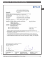
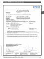
Declarations of conformity can be found online at www.wika.com.
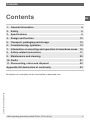
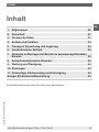
Contents
1. General information 4
2. Safety 5
3. Specifications 9
4. Design and function 12
5. Transport, packaging and storage 13
6. Commissioning, operation 14
7. Information on mounting and operation in hazardous areas 16
8. Safety-related instructions 17
9. Maintenance and cleaning 20
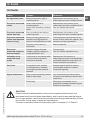
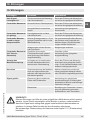
10. Faults 21
11. Dismounting, return and disposal 22
Appendix: EU declaration of conformity 23
Contents

3370964.08 09/20019 EN/DE/FR/ES
4 WIKA operating instructions models TR10-L, TC10-L (Ex d)
EN
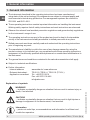
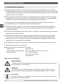
1. General information
■
The instrument described in the operating instructions has been manufactured
using state-of-the-art technology. All components are subject to stringent quality and
environmental criteria during production. Our management systems are certified to
ISO 9001 and ISO 14001.
■
These operating instructions contain important information on handling the instrument.
Working safely requires that all safety instructions and work instructions are observed.
■
Observe the relevant local accident prevention regulations and general safety regulations
for the instrument's range of use.
■
The operating instructions are part of the product and must be kept in the immediate
vicinity of the instrument and readily accessible to skilled personnel at any time.
■
Skilled personnel must have carefully read and understood the operating instructions
prior to beginning any work.
■
The manufacturer's liability is void in the case of any damage caused by using the
product contrary to its intended use, non-compliance with these operating instructions,
assignment of insufficiently qualified skilled personnel or unauthorised modifications to
the instrument.
■
The general terms and conditions contained in the sales documentation shall apply.
■
Subject to technical modifications.
■
Further information:
- Internet address: www.wika.de / www.wika.com
- Relevant data sheet: TE 60.12 (TR10-L), TE 65.12 (TC10-L)
- Application consultant:
Tel.: +49 9372 132-0
Fax: +49 9372 132-406
info@wika.com
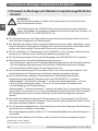
Explanation of symbols
WARNING!
... indicates a potentially dangerous situation that can result in serious injury or
death, if not avoided.
CAUTION!
... indicates a potentially dangerous situation that can result in light injuries or
damage to equipment or the environment, if not avoided.
Information
... points out useful tips, recommendations and information for efficient and
trouble-free operation.
1. General information

WIKA operating instructions models TR10-L, TC10-L (Ex d)
3370964.08 09/20019 EN/DE/FR/ES
5
EN
WARNING!
... indicates a potentially dangerous situation in the hazardous area that can
result in serious injury or death, if not avoided.
WARNING!
... indicates a potentially dangerous situation that can result in burns, caused by
hot surfaces or liquids, if not avoided.
2. Safety
WARNING!
Before installation, commissioning and operation, ensure that the appropriate
thermometer has been selected in terms of measuring range, design and
specific measuring conditions.
Choose the thermowell with regard to the maximum pressure and temperature
(e.g. rating chart in DIN 43772).
Non-observance can result in serious injury and/or damage to the equipment.
Further important safety instructions can be found in the individual chapters of
these operating instructions.
2.1 Intended use
These resistance thermometers and thermocouples are used for temperature measurement
in industrial applications, in hazardous areas.
The instrument has been designed and built solely for the intended use described here, and
may only be used accordingly.
The technical specifications contained in these operating instructions must be observed.
Improper handling or operation of the instrument outside of its technical specifications
requires the instrument to be taken out of service immediately and inspected by an
authorised WIKA service engineer.
If the instrument is transported from a cold into a warm environment, the formation of
condensation may result in instrument malfunction. Before putting it back into operation, wait
for the instrument temperature and the room temperature to equalise.
The manufacturer shall not be liable for claims of any type based on operation contrary to
the intended use.
1. General information / 2. Safety

3370964.08 09/20019 EN/DE/FR/ES
6 WIKA operating instructions models TR10-L, TC10-L (Ex d)
EN
2.2 Personnel qualification
WARNING!
Risk of injury should qualification be insufficient!
Improper handling can result in considerable injury and damage to equipment.
■
The activities described in these operating instructions may only be carried
out by skilled personnel who have the qualifications described below.
■
Keep unqualified personnel away from hazardous areas.
Skilled personnel
Skilled personnel are understood to be personnel who, based on their technical training,
knowledge of measurement and control technology and on their experience and knowledge
of country-specific regulations, current standards and directives, are capable of carrying out
the work described and independently recognising potential hazards.
Special operating conditions require further appropriate knowledge, e.g. of aggressive
media.
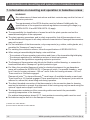
2.3 Special hazards
WARNING!
Observe the information given in the applicable type examination certificate and
the relevant country-specific regulations for installation and use in hazardous
areas (e.g. IEC 60079-14, NEC, CEC). Non-observance can result in serious
injury and/or damage to the equipment.
For further important safety instructions for instruments with ATEX approval, see
chapter 7 “Information on mounting and operation in hazardous areas”.
WARNING!
For hazardous media such as oxygen, acetylene, flammable or toxic gases or
liquids, and refrigeration plants, compressors, etc., in addition to all standard
regulations, the appropriate existing codes or regulations must also be followed.
WARNING!
Protection from electrostatic discharge (ESD) required. The proper use of
grounded work surfaces and personal wrist straps is required when working with
exposed circuitry (printed circuit boards), in order to prevent static discharge
from damaging sensitive electronic components.
To ensure safe working on the instrument, the operating company must ensure
■
that suitable first-aid equipment is available and aid is provided whenever
required.
■
that the operating personnel are regularly instructed in all topics regarding
work safety, first aid and environmental protection and know the operating
instructions and, in particular, the safety instructions contained therein.
2. Safety

WIKA operating instructions models TR10-L, TC10-L (Ex d)
3370964.08 09/20019 EN/DE/FR/ES
7
EN
WARNING!
Residual media in dismounted instruments can result in a risk to persons, the
environment and equipment. Take sufficient precautionary measures.
Do not use this instrument in safety or emergency stop devices. Incorrect use of
the instrument can result in injury.
Should a failure occur, aggressive media with extremely high temperature and
under high pressure or vacuum may be present at the instrument.
2.4 Labelling, safety marking
Product label (example)
2. Safety
TR10-B
1 x Pt100 / B / 3 (F)
-50 ... +250 °C
IEC 60751
Made in Germany
2014
1102AB12
T32.1S.0NI 4 ... 20 mA
-50 ... +250 °C
D-63911 Klingenberg
HART
®
TR10-A-IICZ
1102AB12
1 x Pt100 / B / 3
-50 ... +250 °C
D = 6 mm
525 mm
(F)
D-63911 Klingenberg
IEC 60751
II 3G Ex nA IIC T1 ... T6 Gc X
WARNING! DO NOT OPEN WHILE ENERGIZED!
II 3G Ex nA IIC T1 ... T6 Gc X
II 3D
Ex tc IIIC T440°C ... T80°C Dc X
Tamb T6/T5/T4-T1: -20 ... +55/+70/+80 °C
T
amb T80/95/130-440°C: -20 ... +55/+70/+80 °C
L = 1 µH/m, C = 200 pF/m
Made in Germany 2014
WARNING! POTENTIAL ELECTROSTATIC CHARGING HAZARD!
II 3G Ex nA IIC T1 ... T6 Gc X
II 3D
Ex tc IIIC T440°C ... T80°C Dc X
Tamb T6/T5/T4-T1: -20 ... +55/+70/+80 °C
T
amb T80/95/130-440°C: -20 ... +55/+70/+80 °C
L = 1 µH/m, C = 200 pF/m
Ex n / Ex d
Ex i
EAC (landesspezifisches Zusatzschild)
ΒΗИМАНИЕ!
ПОТЕНЦИАЛЬНЫЙ РИСК НАКОПЛЕНИЯ
ЭЛЕКТРОСТАТИЧЕСКОГО ЗАРЯДА!
СДЕЛАНО В ГЕРМАНИИ
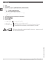
Legend see next page
■
Additional information for Ex instruments
■
Product label for Tx10-K measuring insert

3370964.08 09/20019 EN/DE/FR/ES
8 WIKA operating instructions models TR10-L, TC10-L (Ex d)
EN
2. Safety
Model
Serial number
Information on version (measuring element, measuring range...)
Sensor in accordance with standard (resistance thermometer)
■
F = Thin-film measuring resistor
■
W = Wire-wound measuring resistor
Sensor in accordance with standard (thermocouple)
■
ungrounded
■
grounded
Transmitter model (only for design with transmitter)
Year of manufacture
Approval-related data
Sensor symbol
■
ungrounded = ungrounded welded
■
grounded = welded to the sheath (grounded)
■
quasi grounded = The thermometer is, due to its low insulation clearances between
resistance sensor and sheath, to be considered as grounded.
Before mounting and commissioning the instrument, ensure you read
the operating instructions!

WIKA operating instructions models TR10-L, TC10-L (Ex d)
3370964.08 09/20019 EN/DE/FR/ES
9
EN
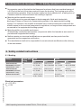
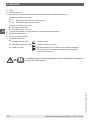
3. Specifications
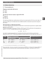
3.1 Resistance thermometer
Sensor connection method
■
2-wire
■
3-wire
■
4-wire
Sensor tolerance value per IEC 60751
■
Class B
■
Class A
■
Class AA
The combinations of a 2-wire connection with class A or class AA are not permissible, since
the lead resistance of the measuring insert negates the higher sensor accuracy.
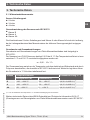
Basic values and tolerance values
Basic values and tolerance values for the platinum measurement resistances are laid down
in IEC 60751.
The nominal value of Pt100 sensors is 100 Ω at 0 °C. The temperature coefficient α can be
stated simply to be between 0 °C and 100 °C with:
α = 3.85 ∙ 10
-3
°C
-1
The relationship between temperature and electrical resistance is described by polynomials,
which are also defined in IEC 60751. Moreover, this standard specifies the basic values in
°C steps in tabular form.
Class Temperature range Tolerance value in °C
Wire-wound (W) Thin-film (F)
B -196 … +600 °C -50 … +500 °C ±(0.30 + 0.0050 | t |)
1)
A -100 … +450 °C -30 … +300 °C ±(0.15 + 0.0020 | t |)
1)
AA -50 … +250 °C 0 … +150 °C ±(0.10 + 0.0017 | t |)
1)
1) | t | is the value of the temperature in °C without consideration of the sign.
For further specifications see WIKA data sheet and the technical information sheet IN 00.17
“Usage limitations and accuracies of platinum resistance thermometers per IEC 60751”.
3. Specifications

3370964.08 09/20019 EN/DE/FR/ES
10 WIKA operating instructions models TR10-L, TC10-L (Ex d)
EN
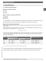
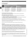
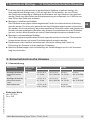
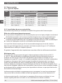
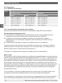
3.2 Thermocouples
3.2.1 Sensor types
Type Recommended max. operating temperature
IEC 60584-1:2013 ASTM E230
Class 1 Class 2 Standard, Special
K 1,000 °C ( 1,832 °F) 1,200 °C (2,192 °F) 1,260 °C (2,300 °F)
J 750 °C (1,382 °F) 750 °C (1,382 °F) 760 °C (1,400 °F)
E 800 °C (1,472 °F) 900 °C (1,652 °F) 870 °C (1,598 °F)
N 1,000 °C ( 1,832 °F) 1,200 °C (2,192 °F) 1,260 °C (2,300 °F)
T 350 °C (662 °F) 350 °C (662 °F) 370 °C (698 °F)
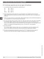
3.2.2 Potential measurement uncertainties
Important factors which counteract the long-term stability of thermocouples.
Ageing effects/poisoning
■
Oxidation processes in thermocouples which are not appropriately protected (“bare”
thermocouple wires) result in falsifications of the characteristic curves.
■
Foreign atoms (poisoning) that diffuse into the original alloys lead to changes of these
original alloys and thus falsify the characteristic curve.
■
The influence of hydrogen leads to the embrittlement of the thermocouples.
The Ni leg of the type K thermocouple is often damaged by sulphur which is contained in
exhaust gases, for example. Type J and T thermocouples age slightly, as the pure metal leg
oxidises first.
In general, rising temperatures cause accelerated ageing effects.
Green rot
If type K thermocouples are used at temperatures from approx. 800 °C to 1,050 °C,
considerable changes of the thermoelectric voltage can occur. The cause of this is a
chromium depletion or the chrome oxidation in the NiCr leg (+ leg). The precondition
for this is a low concentration of oxygen or steam in the immediate environment of the
thermocouple. The nickel leg is not affected by it. The consequence of this effect is a drift of
the measured value caused by decreasing thermoelectric voltage. This effect is accelerated
if there is a shortage of oxygen (reducing atmosphere), since a complete oxide layer, which
would protect it from further oxidation of the chromium, cannot be formed on the surface of
the thermocouple.
The thermocouple is permanently destroyed by this process. The name green rot is derived
from the greenish shimmering colouration on the breaking point of the wire.
The thermocouple type N has in this regard an advantage due to its silicium content. Here, a
protective oxide layer forms on its surface under the same conditions.
3. Specifications

WIKA operating instructions models TR10-L, TC10-L (Ex d)
3370964.08 09/20019 EN/DE/FR/ES
11
EN
K effect
The NiCr leg of a type K thermocouple has an ordered alignment with respect to the
alignment in the crystal lattice below approx. 400 °C. If the thermocouple is heated further, a
transition to a disordered state occurs in the temperature range between approx. 400 °C and
600 °C. Above 600 °C, an ordered crystal lattice is restored.
If these thermocouples cool too quickly (quicker than approx. 100 °C per hour), the
undesirable disordered crystal lattice occurs again during cooling in the range from
approx. 600 °C to approx. 400 °C. In the characteristic curve of type K, however, a
consistently ordered alignment state is assumed and provided with values. This results in
a fault of thermoelectric voltage of up to approx. 0.8 mV (approx. 5 °C) in this range. The K
effect is reversible and is largely eliminated again by annealing above 700 °C, followed by
correspondingly slow cooling.
Thin sheathed thermocouples are particularly sensitive in this regard. Cooling in resting air
can already lead to deviations of 1 °C.
In type N thermocouples, it has been possible to reduce this short-range-order effect by
alloying both legs with silicium.
The application range of these thermometers is limited both by the permissible maximum
temperature of the thermocouple and by the max. temperature of the thermowell material.
Listed models are available both as single or dual thermocouples. The thermocouple will be
delivered with an insulated measuring point, unless explicitly specified otherwise.
Tolerance value
For the tolerance value of thermocouples, a cold junction temperature of 0 °C has been
taken as the basis. When using a compensating cable or thermocouple cable, an additional
measuring deviation must be considered.
For tolerance values and further specifications, see the corresponding WIKA data sheet and
technical information sheet IN 00.23, “Application of thermocouples”.
For further specifications see WIKA data sheet TE 60.12, TE 65.12 and the order
documentation.
For further important safety instructions for operation in hazardous areas, see
chapter 7 “Information on mounting and operation in hazardous areas”.
3. Specifications

3370964.08 09/20019 EN/DE/FR/ES
12 WIKA operating instructions models TR10-L, TC10-L (Ex d)
EN
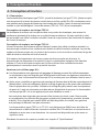
4. Design and function
4.1 Description
The model TR10-L (resistance thermometer) or TC10-L (thermocouple) electrical
thermometers are comprised of a measuring insert which is built into a certified Ex d
housing. In combination with a flame path fitting that is screwed into the head, the measuring
insert functions as a flameproof joint. The measuring insert (TR10-K, TC10-K) is replaceable.
Sensor design in model TR10-L
The measuring resistor is embedded in ceramic powder, heat-resistant potting compound,
cement compound or thermally conductive paste. A one-sided sealed tube, which is welded
to a mineral-insulated cable, forms the external shell of the sensor tip of the measuring
insert.
Sensor design in model TC10-L
The measuring insert of the thermocouple is manufactured from mineral-insulated cable.
The thermocouple consists of the internal leads of the mineral-insulated cable. The weld
spot of the thermocouple is, depending on the design, either ungrounded welded with the
sheath of the mineral-insulated cable or grounded welded.
If the temperature sensor is designed as a grounded thermocouple, the thermocouple is
joined directly to the sheath. Designs with a diameter smaller than 3 mm and with grounded
thermocouples should be considered as galvanically connected with earth potential.
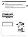
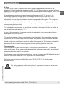
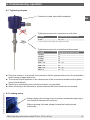
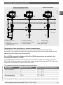
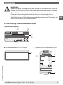
Versions (see figures page 19):
■
Thermometers without a flame path fitting may only be used in combination with a
solid-machined, certified WIKA thermowell with a minimal wall thickness of 1 mm. The
thermometer is marked with IIC and is suitable for use in zone 1.
■
After installation of a flame path fitting into the connection head of the thermometer, a
thermowell is no longer mandatory for certification reasons. In most cases, however, the
use of a thermowell (solid-machined, with a wall thickness of 1 mm) is necessary for
process engineering reasons. The thermometer is marked with IIB + H
2
and is suitable for
use in zone 1.
The design of the thermowell can be selected as desired, but the operational process
data (temperature, pressure, density and flow rate) must be taken into account. If a solid
WIKA thermowell is already available or installed, a flame path fitting is not necessary.
The thermometers models TR10-L or TC10-L are manufactured by WIKA with certified
Ex d connection heads or connection housings. These enclosures and covers are made
from aluminium or stainless steel. The cover is optionally available with a glass window.
Possible sensor measuring ranges see chapter 3 “Specifications”
4. Design and function

WIKA operating instructions models TR10-L, TC10-L (Ex d)
3370964.08 09/20019 EN/DE/FR/ES
13
EN
The following mounting and operating information has been compiled with care.
However, it is not possible to consider all potential usage cases.
4.2 Scope of delivery
Cross-check scope of delivery with delivery note.
5. Transport, packaging and storage
5.1 Transport
Check the instrument for any damage that may have been caused by transport.
Obvious damage must be reported immediately.
5.2 Packaging
Do not remove packaging until just before mounting. Keep the packaging as it will provide
optimum protection during transport (e.g. change in installation site, sending for repair).
5.3 Storage
Permissible conditions at the place of storage:
■
Storage temperature: -20 ... +80 °C
■
Humidity: 35 ... 85 % relative humidity (no condensation)
Avoid exposure to the following factors:
■
Direct sunlight or proximity to hot objects
■
Mechanical vibration, mechanical shock (putting it down hard)
■
Soot, vapour, dust and corrosive gases
Store the instrument in its original packaging in a location that fulfils the conditions listed
above. If the original packaging is not available, pack and store the instrument as described
below:
1. Wrap the instrument in an antistatic plastic film.
2. Place the instrument along with shock-absorbent material in the packaging.
3. If stored for a prolonged period of time (more than 30 days), place a bag containing a
desiccant inside the packaging.
WARNING!
Before storing the instrument (following operation), remove any residual media.
This is of particular importance if the medium is hazardous to health, e.g. caustic,
toxic, carcinogenic, radioactive, etc.
4. Design and function / 5. Transport, packaging and storage

3370964.08 09/20019 EN/DE/FR/ES
14 WIKA operating instructions models TR10-L, TC10-L (Ex d)
EN
6. Commissioning, operation
6.1 Removal and installation of the measuring insert
When servicing is necessary, the flame path fitting must be renewed when replacing the
measuring insert. When recalibrating, make sure that both surfaces of the flameproof joint
(flame path fitting and measuring insert) are not damaged when removing the measuring
insert.
6.2 Electrical connection
Connection to terminal block
For the electrical specifications (e.g. connection diagrams, tolerance values, etc.) please
refer to the data sheets TE 60.12 (for TR10-L) and TE 65.12 (for TC10-L).
Connection to built-in transmitter
For the electrical specifications (e.g. connection diagrams, tolerance values, etc.) please
refer to the relevant operating instructions and/or data sheet for the built-in head-mounted
transmitter.
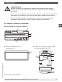
■
Junction between Ex d cable gland and connection head
Threads M20 x 1.5: tightening torques 12 Nm
Threads ½ NPT: tightening torques 30 Nm
■
Junction between cable and Ex d cable gland
Screw the male nut tightly into the adapter (use appropriate tools!)
During installation, take care to
■
Avoid distorting the cable sheath when tightening the male nut.
■
Avoid cutting too deep into the cable sheath.
■
Use suitable cable.
■
Be careful of the clamping zone of the cable gland.
6. Commissioning, operation

WIKA operating instructions models TR10-L, TC10-L (Ex d)
3370964.08 09/20019 EN/DE/FR/ES
15
EN
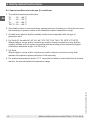
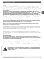
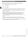
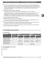
6.3 Tightening torques
Connection head, selectable (example)
Tightening torques for connection to thermowell
Tightening torques for connection to neck tube
Thread Tightening torques in Nm
R 1/2
1)
50 ... 60
1) only for versions with “nipple-union-nipple” neck tube
Thread Tightening torques in Nm
1/2 NPT 35
3/4 NPT 40
G 1/2 B 35
G 3/4 B 40
M14 x 1.5 25 ... 30
M18 x 1.5 35
M20 x 1.5 35 ... 40
M27 x 2 40 ... 45
■
Only ever screw in, or unscrew, the instrument via the spanner-flats and to the prescribed
torque using an appropriate tool.
■
The correct torque depends on the dimensions of the connection thread and the gasket
used (form/material).
■
Screwing or unscrewing the connection head is not permitted.
■
When screwing in the instrument, please observe that the threads are not skewed.
6. Commissioning, operation
6.4 Locking screw
Always tighten the locking screw to prevent unintended opening of
the head with flameproof enclosure.
Before opening the head, always loosen the locking screw
sufficiently.

3370964.08 09/20019 EN/DE/FR/ES
16 WIKA operating instructions models TR10-L, TC10-L (Ex d)
EN
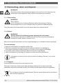
7. Information on mounting and operation in hazardous areas
WARNING!
Non-observance of these instructions and their contents may result in the loss of
explosion protection.
The requirements of the ATEX directive must be followed. Additionally the
specifications of the respective national regulations concerning Ex usage (e.g.
IEC/EN 60079-10 and IEC/EN 60079-14) apply.
■
The responsibility for classification of zones lies with the plant operator and not the
manufacturer/supplier of the equipment.
■
The plant operator guarantees, and is solely responsible, that all thermometers in use
are identifiable with respect to all safety-relevant characteristics. Damaged thermometers
may not be used.
■
For the installation of the thermometer, only components (e.g. cables, cable glands, etc.)
permitted for “flameproof” may be used.
■
For earthing the conductive screen, follow the specifications of IEC/EN 60079-14.
■
When using a transmitter/digital display, note and follow:
- The contents of these operating instructions and those of the transmitter/digital display
- The relevant regulations for installation and use of electrical systems
- The regulation and guidelines regarding explosion protection
■
The flameproof thermometers should only be fitted to certified housing- or connection
heads certified with a “flameproof” ignition protection type.
■
For fitting, the permitted flameproof joints for electrical equipment for gas hazardous
areas are contained in IEC/EN 60079-1. Flameproof joints
1)
for parallel threads
2)
, must
be ≥ 5 mm for housing volumes < 100 cm³ and ≥ 8 mm for housing volumes > 100 cm³.
There must be ≥ 5 threads engaged.
Flameproof joints
1)
for tapered threads
2)
, must have ≥ 5 available threads on each part.
There must be ≥ 3.5 threads engaged. These specifications for flameproof joints must be
adhered to, without fail, when fitting and during operation.
■
The direct threaded connection of the thermometer to the connection head or housing
must not be twisted or opened. Any alignment of the housing may only be made using the
optional “nipple-union-nipple” neck tube.
■
The temperature resistance of the connecting cable must match the permissible
operating temperature of the housings.
For ambient temperatures above 60 °C, heat-resistant connecting cable must be used.
■
No batteries may be built in to the flameproof housing.
7. Information on mounting and operation in hazardous areas
1) Section 5.3 of IEC 60079-1
2) In accordance with table 3 of IEC 60079-1

WIKA operating instructions models TR10-L, TC10-L (Ex d)
3370964.08 09/20019 EN/DE/FR/ES
17
EN
■
No capacitor may be fitted within the flameproof enclosure that has a residual energy of
≥ 0.02 mJ at the end of the time required to open the housing. The housing must not be
opened during operation. After the power supply has been switched off, a waiting time of
2 minutes must be observed before the housing is opened.
■
Mounting within metallic enclosures:
The housing must be grounded against electromagnetic fields and electrostatic
discharge. It does not have to be connected separately to the equipotential bonding
system. It is sufficient if the metallic thermowell has a solid and secured contact with the
metallic vessel or its structural components or pipelines, so long as these components are
connected to the equipotential bonding system.
■
Mounting within non-metallic enclosures:
All electrically-conductive thermometer components within the hazardous area must be
provided with equipotential bonding.
■
Neither repairs nor structural modifications are permitted, and any would void the
guarantee and the respective certification.
■
The manufacturer shall not be responsible for constructional modifications after delivery
of the instruments.
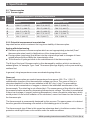
8. Safety-related instructions
8.1 Marking
Design Flame path
fitting
ATEX IECEx
Gas Dust Gas Dust
Solid-machined
thermowell (minimum
wall thickness 1 mm)
No II 2G Ex db IIC
T6...T4 Gb
II 2D Ex tb IIIC
T85 °C Db IP66
Ex db IIC
T6…T4 Gb
Ex tb IIIC
T85 °C Db IP66
Solid-machined
thermowell (minimum
wall thickness 1 mm)
Yes II 2G Ex db IIC
T6...T4 Gb
II 2D Ex tb IIIC
T85 °C Db IP66
Ex db IIC
T6…T4 Gb
Ex tb IIIC
T85 °C Db IP66
Without thermowell Yes II 2G Ex db IIB +
H
2
T6…T4 Gb
- Ex db IIB +
H
2
T6…T4 Gb
-
Electrical parameters
U
m
= DC 30 V
P
m
= 2 W
7. Information on mounting ... / 8. Safety-related instructions

3370964.08 09/20019 EN/DE/FR/ES
18 WIKA operating instructions models TR10-L, TC10-L (Ex d)
EN
8. Safety-related instructions
8.2 Special conditions for safe use (X conditions)
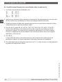
1. The ambient temperature limits are:
T6: -20 ... +60 °C
T5: -20 ... +75 °C
T4: -20 ... +80 °C
T85 °C: -20 ... +60 °C
2. Care shall be taken to ensure that any external sources of heating or cooling do not cause
the assembly to operate outside of the allowable ambient temperature range.
3. All cable entry devices shall be suitably certified and compatible with the type of
protection used.
4. For Ex db IIC (models AE, AF, AG, AK, TXE, TXF, TXG, TXK, YTE, WTE, YTP, WTP):
Where nipples, unions and/or couplers are used for sensor connections, they shall be
suitably certified as Ex d and be compatible with the marking of this assembly. Nipples
shall have a maximum length ≤ 15.24 cm (6").
5. For Ex tb:
Where nipples, unions and/or couplers are used for sensor connections, they shall
maintain the required ingress protection of the assembly.
6. For ambient temperatures above 70 °C, care shall be taken to select cable that is suitably
rated for the intended ambient temperature range.

WIKA operating instructions models TR10-L, TC10-L (Ex d)
3370964.08 09/20019 EN/DE/FR/ES
19
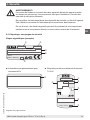
EN
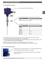
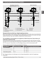
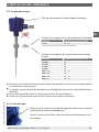
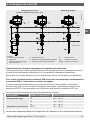
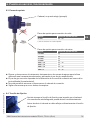
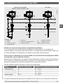
Solid-machined thermowell
(minimum wall thickness 1 mm)
Without thermowell
Legend:
Connection head
Neck tube
Connection to thermowell
Measuring insert
Process connection
Terminal block/transmitter
Flame path fitting
T4
T3
T1
T
undefined
U Insertion length
NL Nominal length
N(M
H
) Neck length
Temperature class classification, ambient temperatures
A heating in the connection head can occur with built-in transmitter through faulty
electronics. The permissible ambient temperatures depend on the housings used and any
additionally-fitted head-mounted transmitter.
For all WIKA connection heads with built-in WIKA temperature transmitters, the
following interrelation is valid:
The temperature increase on the surface of the connection head or housing is less than
25 K if the following conditions are observed: power supply U
B
maximum DC 30 V when the
transmitter is operated in a current limit of 22.5 mA.
This yields the following temperature class classification:
Atmosphere Temperature class Limits for ambient temperature
Gas atmosphere T6 -20 ... +60 °C
T5 -20 ... +75 °C
T4 -20 ... +80 °C
Dust atmosphere T85 °C -20 ... +60 °C
The temperature class is dependent upon the user application and the ambient temperature.
8. Safety-related instructions
14081546.01

3370964.08 09/20019 EN/DE/FR/ES
20 WIKA operating instructions models TR10-L, TC10-L (Ex d)
EN
The permissible ambient temperatures for third-party products can be seen from the relevant
approvals and/or data sheets. However, an impermissible heat reflux from the process which
can exceed the operating temperature of the housing or the temperature class, must be
prevented through suitable heat insulation or a suitably long neck tube.
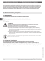
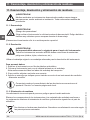
9. Maintenance and cleaning
9.1 Maintenance
The thermometers described here are maintenance-free.
Repairs must only be carried out by the manufacturer.
9.2 Cleaning
CAUTION!
■
Prior to cleaning the electrical connections, disconnect them properly.
■
Clean the instrument with a moist cloth.
■
Electrical connections must not come into contact with moisture.
■
Wash or clean the dismounted instrument before returning it, in order to
protect persons and the environment from exposure to residual media.
■
Residual media in the dismounted instrument can result in a risk to persons,
the environment and equipment. Take sufficient precautionary measures.
For information on returning the instrument see chapter 11.2 “Return”.
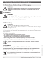
9.3 Calibration, recalibration
It is recommended that the measuring insert is recalibrated at regular intervals (resistance
thermometers: approx. 24 months, thermocouples: approx. 12 months). This period can
reduce, depending on the particular application. The calibration can be carried out by the
manufacturer, as well as on site by qualified technical staff with calibration instruments.
8. Safety-related instructions / 9. Maintenance and cleaning
La page est en cours de chargement...
La page est en cours de chargement...
La page est en cours de chargement...
La page est en cours de chargement...
La page est en cours de chargement...
La page est en cours de chargement...
La page est en cours de chargement...
La page est en cours de chargement...
La page est en cours de chargement...
La page est en cours de chargement...
La page est en cours de chargement...
La page est en cours de chargement...
La page est en cours de chargement...
La page est en cours de chargement...
La page est en cours de chargement...
La page est en cours de chargement...
La page est en cours de chargement...
La page est en cours de chargement...
La page est en cours de chargement...
La page est en cours de chargement...
La page est en cours de chargement...
La page est en cours de chargement...
La page est en cours de chargement...
La page est en cours de chargement...
La page est en cours de chargement...
La page est en cours de chargement...
La page est en cours de chargement...
La page est en cours de chargement...
La page est en cours de chargement...
La page est en cours de chargement...
La page est en cours de chargement...
La page est en cours de chargement...
La page est en cours de chargement...
La page est en cours de chargement...
La page est en cours de chargement...
La page est en cours de chargement...
La page est en cours de chargement...
La page est en cours de chargement...
La page est en cours de chargement...
La page est en cours de chargement...
La page est en cours de chargement...
La page est en cours de chargement...
La page est en cours de chargement...
La page est en cours de chargement...
La page est en cours de chargement...
La page est en cours de chargement...
La page est en cours de chargement...
La page est en cours de chargement...
La page est en cours de chargement...
La page est en cours de chargement...
La page est en cours de chargement...
La page est en cours de chargement...
La page est en cours de chargement...
La page est en cours de chargement...
La page est en cours de chargement...
La page est en cours de chargement...
La page est en cours de chargement...
La page est en cours de chargement...
La page est en cours de chargement...
La page est en cours de chargement...
La page est en cours de chargement...
La page est en cours de chargement...
La page est en cours de chargement...
La page est en cours de chargement...
La page est en cours de chargement...
La page est en cours de chargement...
La page est en cours de chargement...
La page est en cours de chargement...
-
 1
1
-
 2
2
-
 3
3
-
 4
4
-
 5
5
-
 6
6
-
 7
7
-
 8
8
-
 9
9
-
 10
10
-
 11
11
-
 12
12
-
 13
13
-
 14
14
-
 15
15
-
 16
16
-
 17
17
-
 18
18
-
 19
19
-
 20
20
-
 21
21
-
 22
22
-
 23
23
-
 24
24
-
 25
25
-
 26
26
-
 27
27
-
 28
28
-
 29
29
-
 30
30
-
 31
31
-
 32
32
-
 33
33
-
 34
34
-
 35
35
-
 36
36
-
 37
37
-
 38
38
-
 39
39
-
 40
40
-
 41
41
-
 42
42
-
 43
43
-
 44
44
-
 45
45
-
 46
46
-
 47
47
-
 48
48
-
 49
49
-
 50
50
-
 51
51
-
 52
52
-
 53
53
-
 54
54
-
 55
55
-
 56
56
-
 57
57
-
 58
58
-
 59
59
-
 60
60
-
 61
61
-
 62
62
-
 63
63
-
 64
64
-
 65
65
-
 66
66
-
 67
67
-
 68
68
-
 69
69
-
 70
70
-
 71
71
-
 72
72
-
 73
73
-
 74
74
-
 75
75
-
 76
76
-
 77
77
-
 78
78
-
 79
79
-
 80
80
-
 81
81
-
 82
82
-
 83
83
-
 84
84
-
 85
85
-
 86
86
-
 87
87
-
 88
88


WIKA TC10-L tag:model:TR10-L Mode d'emploi
- Taper
- Mode d'emploi
dans d''autres langues
Documents connexes
-
WIKA TC84 Mode d'emploi
-
-
-
-
WIKA CTR3000 Mode d'emploi
-
-
-
-
-
Autres documents
-
Honeywell Tête de visualisation et processeur de signal combinés modèle U2-S Mode d'emploi
-
ABB 266Dx Operating Instructions Manual
-
Tegam 921B-900 Manuel utilisateur
-
Chalmit lighting Lomond Fluorescent | ATEX Guide d'installation
-
Micro Motion Model D DL DT Guide d'installation
-
-
AKO AKO-80004A Converter Manuel utilisateur
-
Garant GridLine casing Mode d'emploi