
HCM 500
Installation and User Manual

PCI Private Limited
35 Pioneer Road North
Singapore 628475
Copyright © 2020 PCI Private Limited. All rights reserved.
PCI Private Limited is a trademark of PCI Private Limited. All other trademarks are the property of their
respective owners.
PCI Private Limited endeavors to ensure that the information in this document is correct and fairly stated,
but PCI Private Limited is not liable for any errors or omissions. Published information may not be up to
date, and it is important to confirm current status with PCI Private Limited.
This technical data may be subject to U.S. and international export, re-export or transfer (export) laws.
Diversion contrary to U.S. and international law is strictly prohibited.
Oct 2020

1. Component Overview
2. FCC, IC and CE Compliance Statements
3. Installation Planning
4. Mounting Options

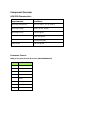
Component Overview
HCM 500 Characteristics
Requirements
Conditions
Operating Temperature
-20° C to +60° C (-4° F to +140° F)
Operating Voltage
12VDC, 24 VDC, 48 VDC
Operating Current
0.5A max @ 12V
0.25A max @ 24V
0.125A max @ 48V
Sleep current
4mA max @ 48V
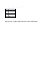
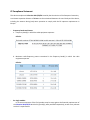
Connector Pinouts
M8 8-pin for communication & interface (M8H4308BMWBG1)
Pin #
Function
1
RS422_TX-
2
RS422_TX+
3
LIN BUS
4
CAN L
5
CAN H
6
RS422_RX+
7
RS422_RX-
8
GND

M8 5-pin for power supply and start up control (M8H4305BMWBG1)
Pin #
Function
1
RESET
2
VIN
3
DIGITAL IN 1
4
DIGITAL IN 2
5
GND
The HCM 500 system has no user-serviceable parts. The HCM 500 contains a Li-ion rechargeable
battery (model: 703343. 3.7V 1000mAh) for back-up power; proper recycling or disposal per local law is
required for all components of the HCM 500.

FCC Compliance Statement
This device complies with Part 15 of the FCC Rules. Operation is subject to the following two conditions:
(1) This device may not cause harmful interference, and (2) this device must accept any interference
received, including interference that may cause undesired operation.
This equipment has been tested and found to comply with the limits for a Class B digital device, pursuant
to Part 15 of the FCC Rules. These limits are designed to provide reasonable protection against harmful
interference in an industrial installation. This equipment generates, uses and can radiate radio frequency
energy and, if not installed and used in accordance with the instructions, may cause harmful interference
to radio communications. However, there is no guarantee that interference will not occur in a particular
installation. If this equipment does cause harmful interference to radio or television reception, which can
be determined by turning the equipment off and on, the user is encouraged to try to correct the
interference by one of the following measures:
- Reorient or relocate the receiving antenna.
- Increase the separation between the equipment and receiver.
- Connect the equipment into an outlet on a circuit different from that to which the receiver is
connected.
- Consult the dealer or an experienced radio/TV technician for help.
FCC Caution: Any changes or modifications not expressly approved by the party responsible for
compliance could void the user's authority to operate this equipment.
This transmitter must not be co-located or operating in conjunction with any other antenna or transmitter.
This device meets all the other requirements specified in Part 15E, Section 15.407 of the FCC Rules.

Radiation Exposure Statement:
This equipment complies with FCC radiation exposure limits set forth for an uncontrolled environment.
This equipment should be installed and operated with minimum distance of 20cm between the radiator
& your body.
Note: The country code selection is for non-US model only and is not available to all US model. Per FCC
regulation, all product marketed in US must fixed to US operation channels only.

IC Compliance Statement
This device complies with ISED’s licence-exempt RSSs. Operation is subject to the following two conditions:
(1) This device may not cause harmful interference, and (2) this device must accept any interference
received, including interference that may cause undesired operation.
Le présent appareil est conforme aux CNR d’ ISED applicables aux appareils radio exempts de licence.
L’exploitation est autorisée aux deux conditions suivantes : (1) le dispositif ne doit pas produire de
brouillage préjudiciable, et (2) ce dispositif doit accepter tout brouillage reçu, y compris un brouillage
susceptible de provoquer un fonctionnement indésirable.
Caution :
(i) where applicable, antenna type(s), antenna models(s), and worst-case tilt angle(s) necessary to remain
compliant with the E.I.R.P. elevation mask requirement set forth in section 6.2.2.3 shall be clearly
indicated.
Advertisement:
Le guide d’utilisation des dispositifs pour réseaux locaux doit inclure des instructions précises sur les
restrictions susmentionnées, notamment :
(i) lorsqu’il y a lieu, les types d’antennes (s’il y en a plusieurs), les numéros de modèle de l’antenne
et les pires angles d’inclinaison nécessaires pour rester conforme à l’exigence de la P.I.R.E.
applicable au masque d’élévation, énoncée à la section 6.2.2.3, doivent être clairement indiqués
Radiation Exposure Statement:
This equipment complies with ISED radiation exposure limits set forth for an uncontrolled environment.
This equipment must be installed and operated with greater than 20cm between the radiator & your body.
Déclaration d'exposition aux radiations:
Cet équipement est conforme aux limites d'exposition aux rayonnements ISED établies pour un
environnement non contrôlé. Cet équipement doit être installé et utilisé à plus de 20 cm entre le
radiateur et votre corps.

CE Compliance Statement
This device complies with Directive 2014/53/EU issued by the Commission of the European Community.
A minimum separation distance of 20 cm must be maintained between the user’s body and the device,
including the antenna during body-worn operation to comply with the RF exposure requirements in
Europe.
- Frequency bands and Powers
a. Frequency band(s) in which the radio equipment operates:
Cellular:
The bands variants of Telit ME910C1-WW module operate in 2G and LTE CATM1/NB1
b. Maximum radio-frequency power transmitted in the frequency band(s) in which the radio
equipment operates
Cellular:
- For single module:
In all cases assessment of the final product must be mass against the Essential requirements of
the Directive 2014/53/EU Articles 3.1(a) and (b), safety and EMC respectively, as well as any relevant
Article 3.2 requirements.

- Antenna:
a. An external 3-in-1 puck antenna manufactured by TE Connectivity (part no. 2363696) will be used
in the device for wireless connectivity. The maximum antenna gain of frequency range 698 MHz
to 960 MHz and 1710 MHz to 3800 MHz is 0 dBi and 2.0 dBi, respectively.
b. A surface-mounted antenna (part no. GA123408BL02) is integrated in device for bluetooth
connectivity. The maximum antenna gain of frequency range 2400 MHz to 2500 MHz is 2.28 dBi.

Installation Planning
Safety, Reliability, and Accessibility
• Use eye protection when using a drill/performing work that may be hazardous to the eyes.
• Use ear protection in noisy work areas.
• Wear appropriate clothing/uniforms and safety shoes.
• Maintain three points of contact when climbing in and out of cab.
• Make sure you know what is behind the area before you drill.
• Install equipment so it will not cause damage to the vehicle or work loose over time.
• Make sure there are no loose components/cables and no unsecured components.
• Use solid mounting surfaces.
• Route all cables away from hot or abrasive areas.
• Choose installation locations where components can be easily serviced.
• Choose installation locations where components are safe from tampering and damage
IMPORTANT SAFETY INFORMATION
------------------------------------------------------------------------------------------------------------------------------------------
WARNING
Do not locate the product where it obstructs the driver’s field of vision, distracts the driver from the driving
task, interferes with the driver’s operation of controls or displays, or creates a safety hazard. Follow all
laws and regulations governing the placement of equipment and mounts.
------------------------------------------------------------------------------------------------------------------------------------------
DO locate the product where:
• it can be safely installed on a secured bracket that is robust enough to minimize any
vibration and sustain the weight of the product.
• the mounting surface is strong enough to support the mounting hardware.
• the mounting surface is flat.
• it does not block the view of the road or mirrors.
• the surrounding area is clear of dash controls and gauges.
• it is not mounted in constant, direct sunlight.

• it does not limit a passenger’s leg room or block access to any other compartments.
• it does not interfere with anyone entering or exiting the vehicle cab.
• it is not likely to impact the driver or passenger in case of an accident or collision.
MAY CONTAIN U.S. AND INTERNATIONAL EXPORT CONTROLLED INFORMATION
DO NOT locate the Product where it:
• obstructs the driver’s field of vision.
• distracts the driver from the driving task.
• interferes with the driver’s operation of controls or shifting.
• obstructs moving parts of the vehicle, if any.
• blocks the deployment of an airbag.
Additional information for selecting an installation location:
• Installations should not obstruct the driver’s field of vision while operating the vehicle, and
should comply with all applicable federal and state laws and regulations regarding
• appropriate installation locations (including restrictions against the mounting of objects on
a vehicle’s windshield) and driver distraction.
• Consider the owner’s preference in selecting the installation location and whether there is
a team or a single driver.
• Once a suitable location is selected, verify that there is nothing behind the mounting
surface that might be damaged by drilling holes.
------------------------------------------------------------------------------------------------------------------------------------------
WARNING
Excess cable can be a tripping hazard. Ensure cable is not draped where it will interfere with either the
driver or passenger as they move within the cab.
------------------------------------------------------------------------------------------------------------------------------------------

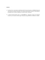
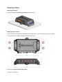
Mounting Condition
Mounting Orientation
Device is mounted in horizontal orientation as below picture
Mounting Screw Locations
There are a total of 4 mounting screw holes, one at each corner, as pointed to by the red arrows below.
Two of the holes are slightly elongated for tolerance purpose.
Fastening using 4 pcs, M5 bolts and washer
Units are in millimeters.
-
 1
1
-
 2
2
-
 3
3
-
 4
4
-
 5
5
-
 6
6
-
 7
7
-
 8
8
-
 9
9
-
 10
10
-
 11
11
-
 12
12
-
 13
13


dans d''autres langues
- English: Husqvarna HCM 500 User manual
Autres documents
-
 Aev Spol WSBRC001 Manuel utilisateur
-
Intermec IM11 Integration Manual
-
Trendnet RB-TEW-840APBO2K Quick Installation Guide
-
Mediatek MT7922A12L Mode d'emploi
-
-
Lantronix Open-Q Mode d'emploi
-
-
-
King WiFiMax KWM1000 Installation And Operating Instructions Manual
-
Telit Wireless Solutions xE910 Manuel utilisateur
