
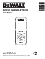
Please read these instructions before operating the product.
www.DEWALT.com
E
NL
GR
PT
FIN
HU
BG
LV
ES
DK
CZ
E
NO
SK
RO
LT
F
SE
RU
PT
PL
SI
EE
TR
HR
DW0165, DW0165S, DW0330S
User Manual
DW0165S

1
2
0.000 m
0.000 m
0.000 m
0.000 m
50.0°
DW0165S
B
DW0
1
6
5
4.5V
DC
D
DW0
1
6
5
4.5V DC
DW0
1
6
5
4.5V
DC
AAA
AAA
AAA
DW0
1
6
5
4.5V DC
AAA
AAA
DW0
1
6
5
4.5V DC
2
Figures
A
4
DW0165
4.5V DC
2
5
6
1
3
7
8
C
3
1
2
4
5
6
0.0000 m
0.0000 m
0.0000 m
0.0000 m
50.0°

3
a
a
50.0°
F
DW0165S
DW0330S
1
2
3
0.0000 m
0.0000 m
0.0000 m
0.0000 m
50.0°
4
=
=
=
=
1
3
4
G
ft/m
E
2

4
Figures
H
J
K
0.0000 m
0.0000 m
0.0000 m
0.7000m
50.0°
I
71.77 in
45.86 in
45.86 in
50.0°
max
min
+
0.3000 m
0.7000 m
1.0000m
50.0°
+
-
/
0.8500m
-
50.0°
0.1500 m
1.0000 m
+
-
/

5
L
0.6000 m
0.4000 m
0.2400 m
50.0°
2
M
N
O
0.7000 m
0.6000 m
0.5000 m
0.2100 m
50.0°
3
2
0.240 m
2
+
0.210 m
0.450 m
2
50.0°
+
-
/
+/-
+/-

6
Figures
1.0100m
2.7390 m
50.0°
2.1000 m
?
P
Q
?
R

7
4.8270m
24.3°
0.0320 m
24.3°
?
S
T

8
Figures
12”
12”
12”
0.000 in
0.00 in
12.0 in
50.0°
a
a
12”
12”
0.000 in
12.0 in
12.0 in
50.0°
a
a
12” 12”
0.000 in
12.0 in
12.0 in
50.0°
a
a
12”
U

9
180°
90°
180°
X
15.0°
15.0°
50.0°
V
?
W

10
E
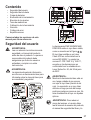
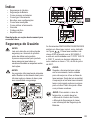
Contents
• User Safety
• Battery Safety
• Loading Batteries
• Turning the Tool On
• Choosing the Settings
• Taking Measurements
• Calibrating the Tool
• Warranty
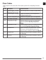
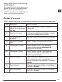
• Error Codes
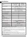
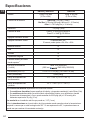
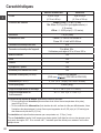
• Specications
Retain all sections of this manual for future
reference.
User Safety
WARNING:
Carefully read the Safety Instructions
and Product Manual before using
this product. The person responsible
for the product must ensure that all
users understand and adhere to these
instructions.
WARNING:
The following label information is
placed on your laser tool to inform you
of the laser class for your convenience
and safety.
DW0165S
4.5V DC
FCC ID: 2ANWFDW0165
IC: 23237-DW0165
DW0165
4.5V DC
DW0330S
4.5V DC
FCC ID: 2ANWFDW0330
IC: 23237-DW0330
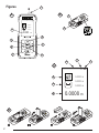
The DW0165/DW0165S/DW0330S tool emits
a visible laser beam, as shown in Figure
A
1
. The laser beam emitted is Laser
Class 2/3R per IEC 60825-1 and complies
with 21 CFR 1040.10 and 1040.11 except for
deviations pursuant to Laser Notice No. 50,
dated June 24, 2007.
WARNING:
While the laser tool is in operation,
be careful not to expose your eyes
to the emitting laser beam (red light
source). Exposure to a laser beam
for an extended time period may be
hazardous to your eyes. Do not look
into the beam with optical aids.
WARNING: To reduce the risk of
injury, user must read the Product User
manual, Laser Safety manual, and
Battery Safety information.
FCC Compliance
This device complies with Part 15 of the FCC
Rules. Operation is subject to the following
two conditions: (1) This device may not cause
harmful interference, and (2) this device must
accept any interference received, including
interference that may cause undesired
operation.
DW0165
4.5V DC
DW0165S
FCC ID: 2ANWF-DW0165
IC: 23237-DW0165
4.5V DC
DW0330S
FCC ID: 2ANWFDW0330
IC: 23237-DW0330
4.5V DC

11
E
FCC Statement
This equipment has been tested and found
to comply with the limits for a Class B digital
device, pursuant to part 15 of the FCC
rules. These limits are designed to provide
reasonable protection against harmful
interference in a residential installation. This
equipment generates, uses, and can radiate
radio frequency energy and, if not installed
and used in accordance with the instructions,
may cause harmful interference to radio
communications. This device is a portable unit.
The exclusion threshold is 0.887<3. However,
there is no guarantee that interference will
not occur in a particular installation. If this
equipment does cause harmful interference
to radio or television reception, which can be
determined by turning the equipment off and
on, the user is encouraged to try to correct the
interference by one or more of the following
measures:
- Reorient or relocate the receiving antenna.
- Increase the separation between the
equipment and the receiver.
- Connect the equipment into an outlet on
a different circuit (not the circuit to which the
receiver is connected).
- Consult the dealer or an experienced radio/
TV technician for help.
Canada, Industry Canada (IC) Notices
Class B digital circuitry of this device complies
with Canadian ICES-003. This device complies
with Industry Canada license-exempt RSS
standard(s). Operation is subject to the
following two conditions: (1) this device may
not cause interference, and (2) this device
must accept any interference, including
interference that may cause undesired
operation of the device.
Under Industry Canada regulations, the radio
transmitter(s) in this device may only operate
using an antenna of a type and maximum (or
lesser) gain approved for the transmitter by
Industry Canada. To reduce potential radio
interference to other users, the antenna type
and its gain should be so chosen that the
equivalent isotropically radiated power (e.i.r.p.)
is not more than that necessary for successful
communication.
Battery Safety
WARNING: Batteries can explode or
leak and cause serious injury or re. To
reduce the risk:
ALWAYS follow all instructions and
warnings on the battery label and
package.
DO NOT short any battery terminals.
DO NOT charge alkaline batteries.
DO NOT mix old and new batteries.
Replace all of them at the same time
with new batteries of the same brand
and type.
DO NOT mix battery chemistries.
DO NOT dispose of batteries in re.
ALWAYS keep batteries out of reach
of children.
ALWAYS remove batteries if the
device will not be used for several
months.
NOTE: Ensure that the recommended
batteries are used.
NOTE: Ensure the batteries are
inserted in the correct manner, with the
correct polarity.

12
E
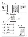
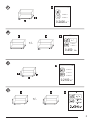
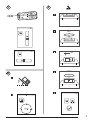
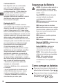
Loading Batteries
1.
Pull up the endpiece on the back of the
tool (Figure
D
1
).
2.
Pull up the battery compartment latch on
the back of the tool (Figure
D
2
and
D
3
).
3.
Insert three AAA batteries, making sure to
position the - and + ends of each battery
as noted inside the battery compartment
(Figure
D
4
).
4.
Push the battery door down until it snaps
in place (Figure
D
5
).
When the tool is ON, the battery level appears
on the screen (Figure
C
1
).
Turning the Tool On
1.
Point the tool's laser (Figure
A
1
) toward
a wall or object, and not toward anyone's
eyes.
2.
Press (Figure
A
3
) to turn the tool
on and display the red laser dot.
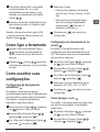
Choosing the Settings
Setting Automatic Turn Off
By default, the tool will automatically turn off
90 seconds after no buttons or options have
been selected. To change when the tool
automatically turns off, follow these steps.
1.
On the first screen (Figure
E
1
), press
to display the Main Menu.
2.
On the Main Menu (Figure
E
2
), select
and press .
3.
On the Settings Menu (Figure
G
), select
and press .
4.
Select the time.
• Choose to turn off the tool after 30 sec,
60 secs, 90 secs, or 300 secs.
• To keep the tool turned on until you
manually turn it off (by pressing and
holding for 10 seconds), select
∞
.
5.
Press to save your setting.
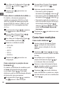
Setting Screen Brightness
By default, the tool's screen will be set at 25%
brightness. To change the brightness level,
follow these steps.
1.
On the first screen (Figure
E
1
), press
to display the Main Menu.
2.
On the Main Menu (Figure
E
2
), select
and press .
3.
On the Settings Menu (Figure
G
), select
and press .
4.
Select the desired brightness level: 25%,
50%, 75%, or 100%.
5.
Press to save your new setting.
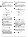
Turning Off the Sound
By default, the tool will beep each time you
take a measurement. You can turn off the
beeps.
1.
On the first screen (Figure
E
1
), press
to display the Main Menu.
2.
On the Main Menu (Figure
E
2
), select
and press .
3.
On the Settings Menu (Figure
G
), select
and press to display .
4.
Press to save your setting.

13
E
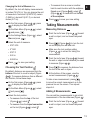
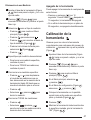
Changing the Unit of Measure
ft/m
By default, the tool will display measurements
in inches (74 9/16 in). You can change the unit
of measure to fractional ft (6'02"9/16), meters
(1.8940 m), decimal ft (6.21 ft), or decimal
inches (3.21 in).
1.
On the first screen (Figure
E
1
), press
to display the Main Menu.
2.
On the Main Menu (Figure
E
2
), select
and press .
3.
On the Settings Menu (Figure
G
), select
ft/m and press .
4.
Select the unit of measure.
• 0'00" 0/00
• 0" 0/00
• 0'00" ft
• 0.00 in
• 0.0000 m
5.
Press to save your setting.
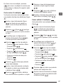
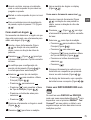
Choosing the Tool Position
By default, distances are measured from the
bottom of the tool to a wall or object (Figure
F
3
). To measure distances from a different
tool location, follow these steps.
1.
On the first screen (Figure
E
1
), press
to display the Main Menu.
2.
On the Main Menu (Figure
E
2
), select
and press .
3.
Select the tool position.
• To measure from the top of the tool
(Figure
F
1
), select .
• To measure from the tripod connection
on the tool (Figure
F
2
), select .
• To measure from a corner or another
hard-to-reach location with the endpiece
flipped open (Figure
D
1
), select
(Figure
F
4
) to measure from the end
of the endpiece.
4.
Press to save your new setting.
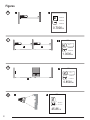
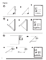
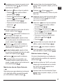
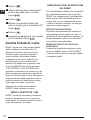
Taking Measurements
Measuring Distance
1.
Point the tool's laser (Figure
A
1
) toward
a wall or object, and not toward anyone's
eyes.
2.
Press (Figure
A
3
) to turn the tool
on and display the red laser dot.
3.
Make sure the tool position setting
(Figure
C
4
) is correct for taking the
measurement.
4.
Point the tool's laser (Figure
A
1
) toward
the wall or object whose distance you need
to measure (Figure
H
1
).
5.
Press to measure the distance from
the tool to the wall or object.
6.
At the bottom of the screen, view the
current measurement (Figure
H
2
).
To take a new measurement, press
to move the current measurement up to the
previous line on the screen. Then repeat
steps 4-6.
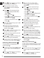
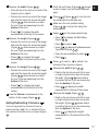
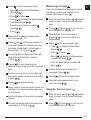
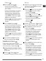
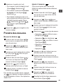
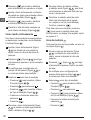
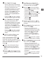
Adding 2 Measurements
You can add two measurements to get a total
measurement of the two distances (Figure
I
).
1.
Point the tool's laser (Figure
A
1
) toward
a wall or object, and not toward anyone's
eyes.

14
E
2.
Press (Figure
A
3
) to turn the tool
on and display the red laser dot.
3.
Make sure the tool position setting
(Figure
C
4
) is correct for taking the
measurement.
4.
Select as the measurement type.
• Press to display the Main Menu
(Figure
E
2
)
• Press to select .
• Press to display the Measurement
Type Menu (Figure
E
3
).
• Press the arrow buttons to select .
• Press .
5.
Press to indicate that you want to add
two measurements.
6.
Point the tool's laser toward the wall
or object whose distance you need to
measure (Figure
I
1
).
7.
Press to measure the distance from
the tool to the first wall or object.
8.
Point the tool's laser toward the next wall
or object (Figure
I
2
).
9.
Press to measure the distance and
add it to the previous measurement.
10.
View the total of the two measurements at
the bottom of the screen (Figure
I
3
).
Subtracting 2 Measurements
You can subtract one measurement from
another (Figure
J
).
1.
Point the tool's laser (Figure
A
1
) toward
a wall or object, and not toward anyone's
eyes.
2.
Press (Figure
A
3
) to turn the tool
on and display the red laser dot.
3.
Make sure the tool position setting
(Figure
C
4
) is correct for taking the
measurement.
4.
Select as the measurement type.
• Press to display the Main Menu
(Figure
E
2
).
• Press to select .
• Press to display the Measurement
Type Menu (Figure
E
3
).
• Press the arrow buttons to select .
• Press .
5.
Press to indicate that you want to
subtract one measurement from another.
6.
Point the tool's laser toward the wall
or object whose distance you need to
measure (Figure
J
1
).
7.
Press to measure the distance from
the tool to the wall or object.
8.
Point the tool's laser toward the wall or
object whose distance is to be subtracted
from the first measurement (Figure
J
2
).
9.
Press to measure the distance and
subtract it from the previous measurement.
10.
View the difference between the two
measurements at the bottom of the screen
(Figure
J
3
).
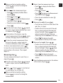
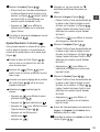
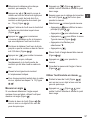
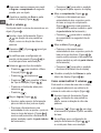
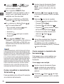
Measuring Continuously
To take a series of measurements as you move
around, change to Continuous Measure mode
(Figure
K
).
1.
Point the tool's laser (Figure
A
1
) toward
a wall or object, and not toward anyone's
eyes.
2.
Press Figure
A
3
) to turn the tool
on and display the red laser dot.

15
E
3.
Make sure the tool position setting
(Figure
C
4
) is correct for taking the
measurement.
4.
Select as the measurement type.
• Press to display the Main Menu
(Figure
E
2
).
• Press to select .
• Press to display the Measurement
Type Menu (Figure
E
3
).
• Press the arrow buttons to select .
• Press .
5.
Point the tool's laser (Figure
A
1
) toward
the wall or object whose distance you need
to measure (Figure
K
1
).
6.
At the bottom of the screen, view the
current measurement (Figure
K
2
), which
will keep changing as you move the tool.
7.
To take the current measurement (from
the tool to the wall or object) and exit
Continuous Measure mode, press .
To take a new measurement, press
to move the current measurement up to the
previous line on the screen. Then repeat
steps 4-7.
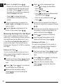
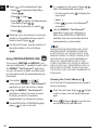
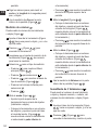
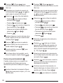
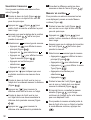
Measuring Area
You can measure the area of a wall, floor, or
object (Figure
L
).
1.
Point the tool's laser (Figure
A
1
) toward
a wall or object, and not toward anyone's
eyes.
2.
Press (Figure
A
3
) to turn the tool
on and display the red laser dot.
3.
Make sure the tool position setting
(Figure
C
4
) is correct for taking the
measurement.
4.
Select as the measurement type.
• Press to display the Main Menu
(Figure
E
2
).
• Press to select .
• Press to display the Measurement
Type Menu (Figure
E
3
).
• Press the arrow buttons to select .
• Press .
5.
Measure the width (Figure
L
1
).
• Point the top of the tool at one side of the
wall, floor, or object.
• Position the tool at one end of the wall,
floor, or object and point the laser dot
across the width. (Figure
L
1
shows
where to position the tool if you are
measuring from the bottom of the tool.)
• Press to display the width
measurement at the top of the screen.
6.
Measure the length (Figure
L
2
).
• Position the tool at one end of the wall,
floor, or object and point the laser dot
across the length. (Figure
L
2
shows
where to position the tool if you are
measuring from the bottom of the tool.)
• Press to display the length
measurement on the second line of the
screen.
7.
View the Area measurement at the bottom
of the screen (Figure
L
3
).

16
E
Adding/Subtracting 2 Areas
You can measure the area of a wall, floor,
or object and then add it to, or subtract it
from, the area of another wall, floor, or object
(Figure
M
).
1.
Point the tool's laser (Figure
A
1
) toward
a wall or object, and not toward anyone's
eyes.
2.
Press (Figure
A
3
) to turn the tool
on and display the red laser dot.
3.
Make sure the tool position setting
(Figure
C
4
) is correct for taking the
measurement.
4.
Select as the measurement type.
• Press to display the Main Menu
(Figure
E
2
).
• Press to select .
• Press to display the Measurement
Type Menu (Figure
E
3
).
• Press the arrow buttons to select .
• Press .
5.
Press to add, or to subtract, the
areas of two walls, floors, or objects.
6.
Measure the width of the first wall, floor, or
object (Figure
D
1
).
• Position the tool at one end of the wall,
floor, or object and point the laser dot
across the width. (Figure
M
1
shows
where to position the tool if you are
measuring from the bottom of the tool.)
• Press to display the width
measurement at the top of the screen.
7.
Measure the length of the first wall, floor,
or object (Figure
M
2
).
• Position the tool at one end of the wall,
floor, or object and point the laser dot
across the length. (Figure
M
2
shows
where to position the tool if you are
measuring from the bottom of the tool.)
• Press to display the length
measurement on the second line of the
screen.
8.
Follow the same steps to measure the
width and length of the second wall, floor,
or object.
9.
View the Area measurement at the bottom
of the screen (Figure
M
3
).
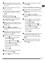
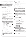
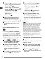
Measuring Volume
You can measure the volume of a room or
object (Figure
N
).
1.
Point the tool's laser (Figure
A
1
) toward
a wall or object, and not toward anyone's
eyes.
2.
Press (Figure
A
3
) to turn the tool
on.
3.
Make sure the tool position setting
(Figure
C
4
) is correct for taking the
measurement.
4.
Select as the measurement type.
• Press to display the Main Menu
(Figure
E
2
).
• Press to select .
• Press to display the Measurement
Type Menu (Figure
E
3
).
• Press the arrow buttons to select .
• Press .

17
E
5.
Measure the width (Figure
N
1
).
• Point the top of the tool at one side of the
target (room or object).
• Position the tool at one end of the target
and point the laser dot across the width.
(Figure
N
1
shows where to position
the tool if you are measuring from the
bottom of the tool.)
• Press to display the width
measurement at the top of the screen.
6.
Measure the length (Figure
N
2
).
• Position the tool at one end of the target
and point the laser dot across the length.
(Figure
N
2
shows where to position
the tool if you are measuring from the
bottom of the tool.)
• Press to display the length
measurement on the second line of the
screen.
7.
Measure the height (Figure
N
3
).
• Position the tool at one end of the target
and point the laser dot across the height.
(Figure
N
3
shows where to position
the tool if you are measuring from the
bottom of the tool).
• Press to display the height
measurement on the third line of the
screen.
8.
View the Volume measurement at the
bottom of the screen (Figure
N
4
).
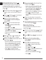
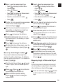
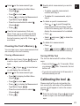
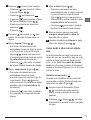
Adding/Subtracting 2 Volumes
You can measure the volume of room or
object and then add it to, or subtract it from,
the volume of another room or object (Figure
O
).
1.
Point the tool's laser (Figure
A
1
) toward
a wall or object, and not toward anyone's
eyes.
2.
Press (Figure
A
3
) to turn the tool
on and display the red laser dot.
3.
Make sure the tool position setting
(Figure
C
4
) is correct for taking the
measurement.
4.
Select as the measurement type.
• Press to display the Main Menu
(Figure
E
2
).
• Press to select .
• Press to display the Measurement
Type Menu (Figure
E
3
).
• Press the arrow buttons to select .
• Press .
5.
Press to add, or to subtract, the
volumes of two rooms or objects.
6.
Measure the width (Figure
O
1
).
• Position the tool at one end of the room
or object and point the laser dot across
the width. (Figure
O
1
shows where
to position the tool if you are measuring
from the bottom of the tool.)
• Press to display the width
measurement at the top of the screen.
7.
Measure the length (Figure
O
2
).
• Position the tool at one end of the room
or object and point the laser dot across
the length. (Figure
O
2
shows where
to position the tool if you are measuring
from the bottom of the tool.)
• Press to display the length
measurement on the second line of the
screen.

18
E
8.
Measure the height (Figure
O
3
).
• Position the tool at one end of the room
or object and point the laser dot across
the height. (Figure
O
3
shows where
to position the tool if you are measuring
from the bottom of the tool).
• Press to display the height
measurement on the third line of the
screen.
9.
Follow the same steps to measure the
width, length, and height of the second
room or object.
10.
View the Volume measurement at the
bottom of the screen (Figure
O
4
).
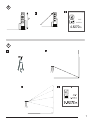
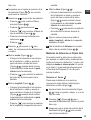
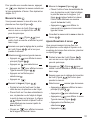
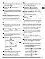
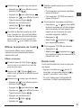
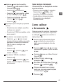
Measuring the Height of a Tall Object
If you need to measure the height of a tall
object (e.g., a tall building), you can calculate
the height based on the distance to 1 point
or the distances from the same point to 2
points on the object. The tool will use the
Pythagorean Theorem (C
2
=A
2
+B
2
) to calculate
the height.
Distance to 1 Point
You can use the distance to one point on a
wall or object (Indirect Height) to determine
its height (Figure
P
).
1.
Point the tool's laser (Figure
A
1
) toward
a wall or object, and not toward anyone's
eyes.
2.
Press (Figure
A
3
) to turn the tool
on and display the red laser dot.
3.
Make sure the tool position setting
(Figure
C
4
) is correct for taking the
measurement.
4.
Select as the measurement type.
• Press to display the Main Menu
(Figure
E
2
).
• Press to select .
• Press to display the Measurement
Type Menu (Figure
E
3
).
• Press the arrow buttons to select .
• Press .
5.
Position the tool opposite the bottom of
the vertical height to be measured (Figure
P
1
).
6.
Point the laser toward the highest point of
the building or object whose height you
need to measure (Figure
P
1
).
7.
Press to measure the distance.
8.
View the height measurement at the
bottom of the screen (Figure
P
2
).
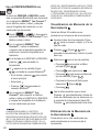
Distances to 2 Points
You can use the distance to two points on
a wall or object (Double Indirect Height) to
determine its height (Figure
Q
).
1.
Point the tool's laser (Figure
A
1
) toward
a wall or object, and not toward anyone's
eyes.
2.
Press (Figure
A
3
) to turn the tool
on and display the red laser dot.
3.
Make sure the tool position setting
(Figure
C
4
) is correct for taking the
measurement.

19
E
4.
Select as the measurement type.
• Press to display the Main Menu
(Figure
E
2
).
• Press to select .
• Press to display the Measurement
Type Menu (Figure
E
3
).
• Press the arrow buttons to select .
• Press .
5.
Position the tool opposite the approximate
center of the vertical height to be
measured (Figure
Q
1
).
6.
Point the laser toward the lowest point of
the building or object whose height you
need to measure (Figure
Q
2
).
7.
Press to measure the distance.
8.
From the same point, aim the laser at
the highest point of the building or object
(Figure
Q
3
).
9.
Press to measure the distance.
10.
On the bottom line of the screen, view the
height of the building or object (Figure
Q
4
).
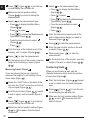
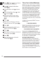
Measuring Partial Height of a Wall
If you need to determine the height of a
section of a wall or object (e.g., the distance
from the ceiling to the top of TV or window on
the wall) (Figure
R
).
1.
Point the tool's laser (Figure
A
1
) toward
a wall or object, and not toward anyone's
eyes.
2.
Press (Figure
A
3
) to turn the tool
on and display the red laser dot.
3.
Make sure the tool position setting
(Figure
C
4
) is correct for taking the
measurement.
4.
Select as the measurement type.
• Press to display the Main Menu
(Figure
E
2
).
• Press to select .
• Press to display the Measurement
Type Menu (Figure
E
3
).
• Press the arrow buttons to select .
• Press .
5.
Point the laser at the highest point of the
wall or object (Figure
R
1
).
6.
Press to measure the distance to
the top of the tall object.
7.
From the same point, aim the laser at
the top of the obstruction on the wall or
object (Figure
R
2
).
8.
Press to measure the distance from
the top of the wall to the obstruction (TV,
window, etc.).
9.
From the same point, aim the laser on a
horizontal line straight ahead toward the
bottom of the wall (Figure
R
3
).
10.
Press to measure the distance.
11.
On the bottom line of the screen, view
the distance between the top of the wall
and the top of the obstruction on the wall
(Figure
R
4
).
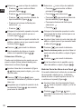
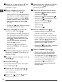
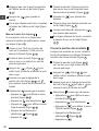
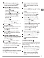
Measuring Height of Obstructed Object
-
Follow these steps to determine the height
of a tall building or object that is blocked by
other buildings or objects (Figure
S
).
1.
Point the tool's laser (Figure
A
1
) toward
a wall or object, and not toward anyone's
eyes.

20
E
2.
Press (Figure
A
3
) to turn the tool
on and display the red laser dot.
3.
Make sure the tool position setting
(Figure
C
4
) is correct for taking the
measurement.
4.
Select as the measurement type.
• Press to display the Main Menu
(Figure
E
2
).
• Press to select .
• Press to display the Measurement
Type Menu (Figure
E
3
).
• Press the arrow buttons to select
(Figure
E
4
).
• Press .
5.
Point the laser at the highest point of the
building, wall, or object (Figure
S
1
).
6.
Press to take the measurement.
7.
On the bottom line of the screen, view the
height of the building or object (Figure
S
2
).
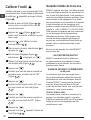
Measuring from a Tripod
If you are placing the tool on a tripod to
measure the height of a tall building, follow
these steps (Figure
T
).
1.
Screw the 1/4-20" hole on the back of the
tool onto the 1/4-20" connection on the top
of your tripod (Figure
T
1
).
2.
Point the tool's laser (Figure
A
1
) toward
a wall or object, and not toward anyone's
eyes.
3.
Press (Figure
A
3
) to turn the tool
on and display the red laser dot.
4.
Make sure the tool position setting (Figure
C
4
) is to measure from the tripod
connection.
5.
Select as the measurement type.
• Press to display the Main Menu
(Figure
E
2
).
• Press to select .
• Press to display the Measurement
Type Menu (Figure
E
3
).
• Press the arrow buttons to select
(Figure
E
4
).
• Press .
6.
Point the laser at the lowest point of the
wall or object whose height you need to
measure (Figure
T
2
).
7.
Press to take the measurement.
8.
Point the laser at other points on the wall
or object (Figure
T
3
).
9.
When ready, press to take the
measurement.
10.
On the bottom line of the screen, view the
height of the wall or object (Figure
T
4
).
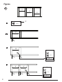
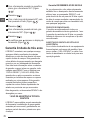
Positioning Studs
a
a
When you are framing a wall, use the
Stakeout feature to easily mark the position
of each stud (Figure
U
).
1.
Point the tool's laser (Figure
A
1
) toward
a wall or object, and not toward anyone's
eyes.
2.
Press (Figure
A
3
) to turn the tool
on and display the red laser dot.
3.
Make sure the tool position setting (Figure
C
4
) is set to to measure from the
back of the tool.
La page charge ...
La page charge ...
La page charge ...
La page charge ...
La page charge ...
La page charge ...
La page charge ...
La page charge ...
La page charge ...
La page charge ...
La page charge ...
La page charge ...
La page charge ...
La page charge ...
La page charge ...
La page charge ...
La page charge ...
La page charge ...
La page charge ...
La page charge ...
La page charge ...
La page charge ...
La page charge ...
La page charge ...
La page charge ...
La page charge ...
La page charge ...
La page charge ...
La page charge ...
La page charge ...
La page charge ...
La page charge ...
La page charge ...
La page charge ...
La page charge ...
La page charge ...
La page charge ...
La page charge ...
La page charge ...
La page charge ...
La page charge ...
La page charge ...
La page charge ...
La page charge ...
La page charge ...
La page charge ...
La page charge ...
La page charge ...
La page charge ...
La page charge ...
La page charge ...
La page charge ...
La page charge ...
La page charge ...
La page charge ...
La page charge ...
La page charge ...
La page charge ...
La page charge ...
La page charge ...
La page charge ...
La page charge ...
-
 1
1
-
 2
2
-
 3
3
-
 4
4
-
 5
5
-
 6
6
-
 7
7
-
 8
8
-
 9
9
-
 10
10
-
 11
11
-
 12
12
-
 13
13
-
 14
14
-
 15
15
-
 16
16
-
 17
17
-
 18
18
-
 19
19
-
 20
20
-
 21
21
-
 22
22
-
 23
23
-
 24
24
-
 25
25
-
 26
26
-
 27
27
-
 28
28
-
 29
29
-
 30
30
-
 31
31
-
 32
32
-
 33
33
-
 34
34
-
 35
35
-
 36
36
-
 37
37
-
 38
38
-
 39
39
-
 40
40
-
 41
41
-
 42
42
-
 43
43
-
 44
44
-
 45
45
-
 46
46
-
 47
47
-
 48
48
-
 49
49
-
 50
50
-
 51
51
-
 52
52
-
 53
53
-
 54
54
-
 55
55
-
 56
56
-
 57
57
-
 58
58
-
 59
59
-
 60
60
-
 61
61
-
 62
62
-
 63
63
-
 64
64
-
 65
65
-
 66
66
-
 67
67
-
 68
68
-
 69
69
-
 70
70
-
 71
71
-
 72
72
-
 73
73
-
 74
74
-
 75
75
-
 76
76
-
 77
77
-
 78
78
-
 79
79
-
 80
80
-
 81
81
-
 82
82


DeWalt DW0330S Manuel utilisateur
- Taper
- Manuel utilisateur
- Ce manuel convient également à
dans d''autres langues
- English: DeWalt DW0330S User manual
- español: DeWalt DW0330S Manual de usuario
- português: DeWalt DW0330S Manual do usuário
Documents connexes
Autres documents
-
Stanley STHT1-77142N Manuel utilisateur
-
Crafstman CMHT77638 Le manuel du propriétaire
-
Skil ME981901 Le manuel du propriétaire
-
Crafstman CMHT77637 Le manuel du propriétaire
-
-
Ryobi ELDM65 Le manuel du propriétaire
-
Bosch GLM 50 CX Manuel utilisateur
-
Stanley STHT77138 Manuel utilisateur
-
-
Milwaukee 48-22-9803 Manuel utilisateur