nsl LVLDL-04-CCT-WH-R-L3-277 Mode d'emploi
- Taper
- Mode d'emploi

LED SERIES
FIXTURE INSTALLATION
INSTALLATION DU LUMINAIRE
Important: Read all instructions in order to ensure safety and proper installation.
Do not modify this fixture. Any modifications may render the product unsafe and void warranty.
N’apportez pas de modifications à cet appareil. Toute altération risque de rendre l’appareil dangereux et
d’annuler la garantie.
This product is suitable for wet locations.
Ce produit convient aux endroits humides.
MAINTENANCE
ENTRETIEN
Limited Warranty
The warranty applies to the product from the original date of purchase for five (5) years
against manufacturing defects. The owner must provide a copy of the original proof of
purchase. The manufacturer's obligation under this warranty is limited to repairing or
replacing the component. It is not related in any way to the cost of the connection, the
installation of the replacement parts or cost of transport.
Garantie Limitée
Cette garantie limitée s'applique pour une période de cinq (5) ans suivant la date de l'achat
par l'acheteur original. Une copie de la facture originale sera requise pour procéder avec
toute demande. L'obligation du fabriquant se limite à la réparation ou remplacement de
l'unité. L'obligation de cette garantie ne comprend aucun frais d'installation ni des frais de
transport.
PARTS LIST /
LISTE DES COMPOSANTS
Remote driver / Commande à distance
Light panel / Panneau d’éclairage
Spring clips / Clavettes
Connector / Connecteur
Lisez toutes les instructions afin d’assurer une bonne installation en toute sécurité.
120V-277V 3 Color Temperature
LED Thin Line Down Light
2700K
3000K
4000K
LVLDL-04-CCT-WH-R-L3-277
LVLDL-06-CCT-WH-R-L3-277
0-10V dimmable on 120V AC (non-dimmable on 277V AC)

Turn power OFF from electrical panel before installation or
maintenance.
WARNING
Mettez l’interrupteur hors tension ou coupez le courant
avant de remplacer ou d’entretien.
MISE EN GARDE
GUIDE D'INSTALLATION
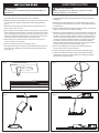
Fig. 3
Fig. 1 Fig. 2
Fig. 4
Hole diameter/Diamètre de perforation:
LVLDL-04-CCT-WH-R-L3-277 4.33” (110mm)
LVLDL-06-CCT-WH-R-L3-277 6.3” (160mm)
1. Turn power OFF from the electrical panel prior to installation.
2. Determine the location for installation and cut ceiling hole in accordance with
cut-hole dimensions. Refer to Hole Diameter table for appropriate sizes.
(Fig. 1)
3. Insert the electrical cable through the knockout of the remote driver, and
secure it with a cable connector.
4. Strip 1/3” (8mm) of the insulation off each incoming 120V (277V) power wire.
Connect white wire (neutral) to push-in connector on white wire from remote
driver. Connect black incoming 120V (277V) power wire (hot wire) to push-in
connector on black wire from remote driver. Connect ground wire to push-in
connector from that non-insulated wire is not exposed. (Fig. 2)
5. Place all wiring and connections back in to the box and close the cover.
Connect the driver to the light panel.
6. Insert remote driver through the mounting hole. (Fig. 3)
7. Push spring-loaded clips on the xture upwards and insert xture base in to
the mounting hole. Release the clips and xture will be pulled ush to the
ceiling. (Fig. 4)
1. Coupez l’électricité à partir du panneau électrique avant de commencer
l’installation.
2. Déterminez un endroit approprié pour l’encastré. Mesurez et coupez un
trou conformément aux dimensions coupe-trous. Voir le tableau approprié
à la taille. (Fig. 1)
3. Insérez le câble d’alimentation électrique par la provision du commande à
distance, et le xer avec un connecteur de câble.
4. Dénuder 1/3 po (8mm) d’isolation de chaque l d’entrée de courant de 120
(277) volts. Brancher le l blanc (neutre) dans le connecteur à poussée sur
le l blanc venant du comande à distance. Brancher le l noir d’entrée de
120 (277) volts (l sous tension) dans le connecteur à poussée du l noir
venant du commmand à distance. Brancher le l de mise à la terre dans
le connecteur du l de mise à la terre relié à la commande à distance.
Pousser tous les ls fermement à fond dans les connecteurs pour éviter
que toute partie non isolée des ls soit exposée. (Fig. 2)
5. Placez tout le câblage et les connexions dans la boîte et fermez le
couvercle. Branchez le circuit et le luminaire.
6. Insérez la commande à distance à travers le trou de montage. (Fig. 3)
7. Pousser les clavettes du luminaire vers le haut et insérez la base de
l’appareil dans le trou de montage. Relâchez les clavettes et l’appareil
sera tiré au ras du plafond. (Fig. 4)
Turn power OFF from electrical panel before installation or
maintenance.
WARNING
Mettez l’interrupteur hors tension ou coupez le courant
avant de remplacer ou d’entretien.
MISE EN GARDE
GUIDE D'INSTALLATION
Fig. 3
Fig. 1 Fig. 2
Fig. 4
Hole diameter/Diamètre de perforation:
-
 1
1
-
 2
2


nsl LVLDL-04-CCT-WH-R-L3-277 Mode d'emploi
- Taper
- Mode d'emploi
dans d''autres langues
Autres documents
-
Cooper Lighting IB517071ML Manuel utilisateur
-
 MaxLite FlatMAX Manuel utilisateur
-
MaxLite LSU4U23WCSCR Manuel utilisateur
-
-
C-LITE C-CP-B-BRQ Series Manuel utilisateur
-
 MaxLite RCF832WCSDW Manuel utilisateur
-
C-LITE C-AR-A-SAL-SCCT Guide d'installation
-
C-LITE C-LITE C-WP-C-TR Series LED Wall Pack Manuel utilisateur
-
Fulham VPR-22-MU-25-9TW-A Manuel utilisateur
-
MaxLite RRCX25CSD Manuel utilisateur

