Modern Forms FR-W2003 Slim Mode d'emploi
- Catégorie
- Ventilateurs ménagers
- Taper
- Mode d'emploi

Slim
Installation Instructions
works with the
Google Assistant

FR-W2003
Slim Instructions2
Please read and
save these instructions
before installation
DO NOT RETURN TO STORE

FR-W2003Slim Instructions 3
For all questions about your ceiling fan please read all included
instructions, installation procedures, troubleshooting guidelines
and warranty information before starting installation.
For missing parts or general inquiries call our trained technical staff at:
1-866-810-6615 option 1
MON-FRI 8AM-8PM EST
Email: customerservice@modernforms.com
Or live chat at modernforms.com
For fast service have the following information below when you call:
1. Model Name and Number
2. Part Number and Part Description
3. Date Of Purchase and Purchase Location
1-866-810-6615 option 2
MON-FRI 8AM-8PM EST
Email: fansupport@modernforms.com
General Inquiries
Fan Support

FR-W2003
Slim Instructions4
For operation, maintenance, and troubleshooting information,
visit http://modernforms.com/fan-support/
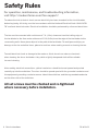
To reduce the risk of electric shock, ensure electricity has been turned off at the circuit breaker
before beginning. All wiring must be in accordance with the National Electrical Code “ANSI/NFPA
70” and local electrical codes. Electrical installation should be performed by a licensed electrician.
The fan must be mounted with a minimum of 7 ft. (2.1m) clearance from the trailing edge of
the fan blades to the floor and a minimum of 1.5 ft (0.5m) from the edge of the fan blades to the
surrounding walls. Never place objects in the path of the fan blades. To avoid personal injury or
damage to the fan and other items, please be cautious when working around or cleaning the fan.
To avoid electrical shock or damage to the motor or finish, do not use water or chemicals
when cleaning the fan or fan blades. A dry cloth or lightly dampened cloth will be suitable
for most cleaning.
After making electrical connections, spliced conductors should be turned upward and pushed
carefully up into the outlet box. The wires should be spread apart with the grounded conductor and
the equipment-grounding conductor on one side of the outlet box, and the ungrounded conductor
on the other side of the outlet box.
All set screws must be checked and re-tightened
where necessary before installation.
Safety Rules

FR-W2003 Slim Instructions 5
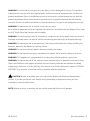
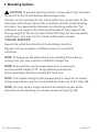
WARNING: Do not install or use your fan if any part(s) is/are damaged or missing. This product
is designed for use only with the supplied parts and/or accessories designated for use with this
product by Modern Forms. Substitution of parts or accessories not designated for use with this
product by Modern Forms could result in personal injury or property damage and will void the
warranty. Contact an authorized dealer or the manufacturer if any parts are damaged or missing.
WARNING: To reduce the risk of electric shock, this fan must
be installed and operated with the supplied wall control, or controlled from the Modern Forms app
or Wi-Fi Touch Panel Wall Control (not included).
WARNING: Do not use power tools to assemble or install your fan. Using power tools can result in
improper assembly which can lead to noise or fan damage,personal injury or property damage.
WARNING: To reduce the risk of personal injury, do not bend the blade arms when installing the
brackets, balancing the blades or cleaning the fan.
WARNING: Do not insert foreign objects between rotating fan blades.
WARNING: Do not operate fan unless fan blades are in place. Noise and fan damage can occur
WARNING: This appliance is not intended for use by young children without supervision.
WARNING: To reduce the risk of fire, electric shock, personal injury or damage to the fan or other
items, the outlet box and support structure must be securely mounted and capable of reliably
supporting a minimum of 35 Ibs (15.9 kg). Use only UL/cUL listed outlet boxes marked “FOR FAN
SUPPORT.” Use only the screws and washers provided with the outlet box.
CAUTION: Before assembling your fan, refer to the “Making the Electrical Connections“
section. If you feel you do not have enough wiring knowledge or experience, have your fan
installed by a licensed electrician.
NOTE: Before servicing or cleaning the fan, switch power off at the circuit breaker.

FR-W2003
Slim Instructions6
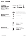
Get Smart...
Integrates
seamlessly with:
devices you already own
works with the
Google Assistant
Premium smart
features:
Accessories:
DC
MOTOR
complement high quality materials
personalize your experience
Quiet, reliable, and up to 70%
PRUHHɝFLHQWWKDQ$&IDQV
:L)LDQG%OXHWRRWKHQDEOHG
IRUȵH[LEOHFRQWURO
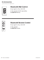
%OXHWRRWK:DOO&RQWURO
'LPVOLJKWWR_212))
IDQVSHHGV_6ROGVHSDUDWHO\
F-WCBT-WT :KLWH
%OXHWRRWK5HPRWH&RQWURO
'LPVOLJKWWR_212))
IDQVSHHGV
F-RCBT-WT :KLWH
Wet Location-listed to the strictest
UL/cUL safety regulations. Finished
and rated for interior and exterior use

FR-W2003 Slim Instructions 7
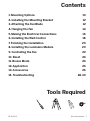
Contents
Tools Required
1. Mounting Options 10
2. Installing the Mounting Bracket 12
3. Attaching the Fan Blade 12
4. Hanging the Fan 14
5. Making the Electrical Connections 16
6. Installing the Wall Control 18
7. Finishing the Installation 20
8. InstallIng the Luminaire Module 20
9. Controlling the Fan 22
10. Reset 24
11. Breeze Mode 24
12. Application 24
13. Accessories 26
14. Troubleshooting 28-30

FR-W2003
Slim Instructions8
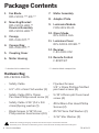
Package Contents
• Safety Cable
• 6.5” x 19 x 2mm Flat washer (1)
• Safety Cable #10 x 76mm
Pan head Philips wood screw (1)
• Safety Cable 3/16” (5.2 x 8.4
x1mm)Spring washer (1)
• Blade Screws 3/16*12 mm
Philip washer head screws (10)
Hardware Bag
RPL-FR2003-PARTS
** denotes finish code of fan *** denotes blade sweep of fan
Before discarding packaging materials be certain all parts have been removed.
Place the parts from the hardware bag into a small container to keep them from being lost.
• Flywheel Screws
1/4” x 11mm Phillips/Slotted
pan head screws (4)
• 5/32”x25mm phil truss head
screw (4)
• #10x38mm Pan Head Phillip
Screws (2)
• Ø5*14*1mm Flat Washer (2)
• 3/16” Star Washer (2)
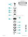
7. Motor Assembly
8. Adapter Plate
9. Luminaire Module
F3IN-120V-R1-30
10. Glass Shade
RPL-F2003-GLA
11. Luminiare Cover
RPL-F2003-COVER-**
12. Receiver
F-R3-2003-052
13. Remote Control
F-RCBT-WT
1. Fan Blade
RPL-F2003-***-BD-**
2. Mounting Bracket
RPL-F2003-HGR-**
Downrod Assembly
RPL-F2003-HGR-**
3. Canopy
RPL-CAN-OCT-**
4. Canopy Ring
RPL-CAN-OCT-**
5. Coupling Cover
6. Motor Housing

FR-W2003 Slim Instructions 9
MAC ID
13
6
8
9
11
10
12
7
5
4
3
2
Hanging Weight: OEV
1
IMPORTANT: Please make note of
the MAC ID on the receiver and
keep it in a safe place.

FR-W2003
Slim Instructions10
1. Mounting Options
CAUTION: To prevent electrical shock, ensure electricity has been
turned off at the circuit breaker before beginning.
If there isn’t an existing UL/cUL listed outlet box, please refer to the
following instructions. Secure the outlet box directly to the building
structure. Use appropriate fasteners and building materials. The
outlet box and support structure must be able to fully support the
moving weight of the fan (at least 35 lbs/15.9 kg). Do not use plastic
outlet boxes. Use only UL/cUL listed outlet boxes marked
“FOR FAN SUPPORT.”
Secure the outlet box directly to the building structure.
Figures 1-1C are examples of different ways to mount the
outlet box.
NOTE: To hang your fan where there is an existing fixture but no
ceiling joist, you may need an installation hanger bar.
NOTE: Downrod fans can be suspended up to a maximum
recommended length of 72” using additional downrods
(sold separately) and the included 80” lead wire.
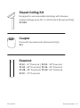
NOTE: The sloped ceiling kit (sold separately) is required for sloped
ceiling applications, and will accommodate slopes up to 45° (Fig. 1B).
NOTE: You may need a longer downrod to maintain proper blade
clearance when installing on a steep, sloped ceiling (Fig. 1B).

FR-W2003 Slim Instructions 11
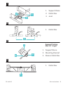
1
1A
1B
1C
1
1
2
1
1
2
3
3
1. Support Brace
2. Outlet Box
3. Joist
1. Support Brace
2. Mounting Bracket
3. Recess Outlet Box
1. Outlet Box
1. Outlet Box
Support Ceiling
Max 30° Angle

FR-W2003
Slim Instructions12
2. Installing the Mounting Bracket
Remember to disconnect the power at the circuit breaker.
1. (Fig. 2) illustrates how to mount the outlet box.
2. Remove 1 set screw from mounting bracket and set aside
for use in Finishing the Installation.
3. Pass supply wires through mounting bracket and secure
to outlet box.
1. Insert blades in slots, aligning with motor assembly holes (Fig. 3).
2. Secure blades with blade attachment screws & washers.
3. Attach the motor assembly to the motor housing (Fig. 3A).
3. Attaching the Fan Blade

FR-W2003 Slim Instructions 13
2 3
3A

FR-W2003
Slim Instructions14
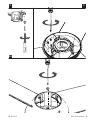
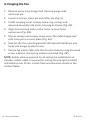
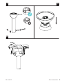
1. Remove screw from hanger ball. Remove hanger ball
and cross pin.
2. Loosen 2 screws, clevis pin and cotter pin (Fig. 4).
3. Install coupling cover, canopy screw ring, canopy and
downrod assembly into motor housing as shown (Fig. 4A).
4. Align downrod and motor collar holes, re-insert pins
and screws (Fig. 4B).
5. Slip up canopy and canopy screw cover. Re-install hanger ball
with cross pin in correct place (Fig. 4A).
6. Seat all into the mounting bracket. Rotate until ball drops and
locks into hanger bracket screw.
7. Secure the safety cable into the structure beams using the wood
screw, washers, and spring washers provided (Fig. 4B).
NOTE: Safety cable is required for all ceiling fan installations in
Canada. Safety cable is required for ceiling fan and light (combo)
installations over 35 lbs. in both flush and downrod models in the
United States.
4. Hanging the Fan

FR-W2003 Slim Instructions 15
4B
4 4A

FR-W2003
Slim Instructions16
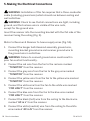
5. Making the Electrical Connections
WARNING: Installation of this fan requires that a three-conductor
cable (including ground wire) which should run between ceiling and
wall outlet box.
WARNING: Check to see that all connections are tight, including
ground, and that no bare wire is visible at the wire nuts,
except for the ground wire.
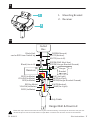
Insert the receiver into the mounting bracket with the flat side of the
receiver facing the ceiling (Fig. 5).
Motor to Receiver & Receiver to house supply wires (Fig. 5A).
1. Connect the hanger ball/downrod assembly ground wire,
mounting bracket ground wire and receiver ground wire to
the ground wire in outlet box.
WARNING: Failure to connect ground wires could result in
poor fan control functionality.
2. Connect the red wire from the fan to the red wire marked
“TO MOTOR” from the receiver.
3. Connect the grey wire from the fan to the grey wire marked
“TO MOTOR” from the receiver.
4. Connect the yellow wire from the fan to the yellow wire marked
“TO MOTOR” from the receiver.
5. Connect the white wire from the fan to the white wire marked
“FOR LIGHT” from the receiver.
6. Connect the blue wire from the fan to the blue wire marked
“FOR LIGHT” from the receiver.
7. Connect the black (hot) wire from the ceiling to the black wire
marked “AC in L” from the receiver.
8. Connect the white (neutral) wire from the ceiling to the white
wire marked “AC in N” from the receiver.

FR-W2003 Slim Instructions 17
Follow the steps above to connect the fan to your household wiring. Use the plastic wire nuts with your fan.
Secure the plastic wire nuts with electrical tape. Make sure there are no loose strands or connections.
5
5A
1
2
1. Mounting Bracket
2. Receiver
Black(Hot)
can be RED from Switch leg
Black(Line in H)
RED(to Motor)
GREEN(Ground)
BLUE (to Light)
BLUE(for Light)
GREEN(GND Must Use)
GREEN(Hanger Bracket Ground)
GREEN(Hanger Bracket Ground)
RED(to Motor)
GREY(to Motor)
WHITE(Neutral)
WHITE(to Light)
WHITE(Neutral)
Safety Cable
GREY(to Motor)
YELLOW(to Motor)
WHITE(Line in N)
YELLOW(to Motor)
Outlet
Box
Receiver
Hanger Ball & Downrod
Hanger
Bracket

FR-W2003
Slim Instructions18
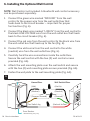
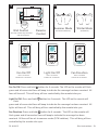
6. Installing the Optional Wall Control
NOTE: Wall Control not included. A bluetooth wall control accessory
can be purchased separately.
1. Connect the green wire marked “GROUND” from the wall
control to the copper wire from the wall outlet box that
feeds back to the circuit breaker – important for proper
fan function (Fig. 6).
2. Connect the black wire marked “LINE IN” from the wall control to
the black LINE VOLTAGE wire from the wall outlet box that feeds
back to the circuit breaker (Fig. 6).
3. Connect the red wire from the wall control to the black wire from
the wall outlet box that feeds up to the fan (Fig. 6).
4. Connect the white wire from the wall control to the white
(neutral) wire from the wall outlet box (Fig. 6).
5. Carefully tuck the wire connections inside the outlet box.
Secure the wall control with the two (2) wall control screws
provided (Fig. 6A).
6. Attach the wall mounting plate over the wall switch and secure
with the two (2) wall mounting plate screws provided (Fig. 6A).
7. Fasten the wall plate to the wall mounting plate (Fig. 6A).
6
Wall Switch WiresHouse Wires
(Hot In)
(Neutral)
(Ground)
(Hot out to Fan)Fan Switch leg
(Copper/Ground)
(Neutral)
(Hot)
From Breaker
* Home Wiring may vary
to Fan

FR-W2003 Slim Instructions 19
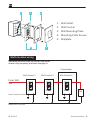
6A
Multi-location wiring
1 2 3
54
1. Wall Outlet
2. Wall Control
3. Wall Mounting Plate
4. Mounting Plate Screws
5. Wallplate
Individually pair each of the wall controls with the fan
receiver using the pairing instruction. See page 23.
Line/Hot
Red
Green (Green or Bare)
Wall Control 1 Wall Control 2 Wall Control 3
If Applicable
FAN
Neutral/White

FR-W2003
Slim Instructions20
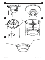
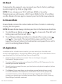
7. Finishing the Installation
1. Secure wire connectors with supplied wire ties.
2. Install canopy to mounting bracket with the screw
removed in section 4 (Fig. 7).
3. Install canopy screw ring as shown (Fig. 7A).
8. Installing the Luminaire Module
1. Remove 1 of 3 screws and loosen the others (Do Not Remove) (Fig. 8).
2. Using the screw from the previous step, install the adapter plate.
NOTE: If you are not installing the luminaire module skip to step 7.
3. Remove 3 screws from the outer perimeter.
4. Attach LED wires from motor assembly to luminaire module (Fig. 8A).
5. Secure the luminaire module with the 3 previously removed screws to
the adapter plate (Fig. 8A).
6. Install glass shade without over-tightening (Fig. 9).
7. Similar to (Fig. 9) install optional metal light cover as shown.
NOTE: Add metal light cover if you do not need lighting function or
prefer a different aesthetic.
NOTE: Do not connect the LED connector wires if you are using the
metal light plate.
La page charge ...
La page charge ...
La page charge ...
La page charge ...
La page charge ...
La page charge ...
La page charge ...
La page charge ...
La page charge ...
La page charge ...
La page charge ...
La page charge ...
La page charge ...
La page charge ...
La page charge ...
La page charge ...
-
 1
1
-
 2
2
-
 3
3
-
 4
4
-
 5
5
-
 6
6
-
 7
7
-
 8
8
-
 9
9
-
 10
10
-
 11
11
-
 12
12
-
 13
13
-
 14
14
-
 15
15
-
 16
16
-
 17
17
-
 18
18
-
 19
19
-
 20
20
-
 21
21
-
 22
22
-
 23
23
-
 24
24
-
 25
25
-
 26
26
-
 27
27
-
 28
28
-
 29
29
-
 30
30
-
 31
31
-
 32
32
-
 33
33
-
 34
34
-
 35
35
-
 36
36


Modern Forms FR-W2003 Slim Mode d'emploi
- Catégorie
- Ventilateurs ménagers
- Taper
- Mode d'emploi
dans d''autres langues
Documents connexes
-
Modern Forms FH-W2003 Slim Flush Mode d'emploi
-
-
-
-
-
-
-
-
-
Autres documents
-
 Lucid FR-W2304 Matte Black Blades Downrod Ceiling Fan Manuel utilisateur
-
 Kichler Lighting Jade 300030 Manuel utilisateur
-
Kichler 310155SBK Manuel utilisateur
-
 Kichler Lighting Motu Manuel utilisateur
-
 Kichler Lighting 310204WCP Manuel utilisateur
-
-
 Kichler Lighting 300365MWH Manuel utilisateur


