La page est en cours de chargement...

INSTRUCTION MANUAL
Product images may vary slightly from actual product.
Cameron
™

KICHLER.COM

TABLE OF CONTENTS
SAFETY RULES ................................................................. 4
TOOLS AND MATERIALS REQUIRED ....................... 5
PACKAGE CONTENTS ....................................................5
MOUNTING OPTIONS .....................................................6
HANGING THE FAN ......................................................7-9
INSTALLATION OF SAFETY SUPPORT ..................10
MAKE THE ELECTRICAL CONNECTIONS .....11-12
FINISHING THE INSTALLATION................................12
ATTACHING THE FAN BLADES .................................13
INSTALLING THE LIGHT PLATE ............................... 13
INSTALLING THE LED LIGHT KIT .............................14
INSTALLING THE GLASS SHADE ..............................14
INSTALLING THE BATTERIES ....................................15
OPERATING INSTRUCTIONS ...............................16-17
INSTALLING THE COOLTOUCH™
CONTROL SYSTEM WALL PLATE ............................18
INSTALLING THE TRANSMITTER ............................19
TROUBLESHOOTING.............................................20-21
SPECIFICATIONS.............................................................21
FCC INFORMATION ...................................................... 22
3
Cameron
™
|

SAFETY RULES
1. To reduce the risk of electric shock, ensure electricity has been
turned o at the circuit breaker or fuse box before beginning.
2. All wiring must be in accordance with the National Electrical
Code and local electrical codes. Electrical installation should
be performed by a qualified licensed electrician.
3. WARNING: To reduce the risk of fire, electric shock, or
personal injury, use mounting screws provided with the
outlet box. Most outlet boxes commonly used for the
support of light fixtures are not acceptable for fan support
and may need to be replaced. Due to the complexity of the
installation of this fan, a qualified licensed electrician is
strongly recommended.
4. The outlet box and support structure must be securely
mounted and capable of reliably supporting a minimum of
50 pounds. Use only CUL Listed outlet boxes marked “FOR
FAN SUPPORT”.
5. The fan must be mounted with a minimum of 7 feet
clearance from the trailing edge of the blades to the floor.
6. Do not operate reversing switch while fan blades are in
motion. Fan must be turned o and blades stopped before
reversing blade direction.
7. Avoid placing objects in the path of the blades.
8. To avoid personal injury or damage to the fan and other
items, be cautious when working around or cleaning the fan.
WARNING
TO REDUCE THE RISK OF FIRE, ELECTRIC SHOCK OR
PERSONAL INJURY, MOUNT FAN TO OUTLET BOX
MARKED “ACCEPTABLE FOR FAN SUPPORT”.
9. Do not use water or detergents when cleaning the fan or fan
blades. A dry dust cloth or lightly dampened cloth will be suitable
for most cleaning.
10. After making the electrical connections, spliced conductors should
be turned upward and pushed carefully up into outlet box. The
wires should be spread apart with the ground wire and white
(common) wire to one side with the black (load) wire to the other
side of the outlet box.
11. Electrical diagrams are reference only. Light kits that are not
packed with the fan must be CUL Listed and marked suitable for
use with the model fan you are installing. Switches must be CUL
General Use Switches. Refer to the Instructions packaged with the
light kits and switches for proper assembly.
WARNING
TO REDUCE THE RISK OF PERSONAL INJURY, DO NOT BEND
THE BLADE BRACKETS (ALSO REFERRED TO AS FLANGES)
DURING ASSEMBLY OR AFTER INSTALLATION. DO NOT INSERT
OBJECTS IN THE PATH OF THE BLADES.
SPECIAL NOTICE
This appliance is equipped with a “Wattage Limiting Device”
required by the United States Department of Energy. The
device has been installed at the factory and can not be removed.
Installing Lamps in excess of 75 total watts will disable the unit’s
light fixture. If this should happen, you will need to reset the
lighting fixture by turning the power o to the ceiling fan
and/or light fixture, reinstalling lamps totaling less that
75 watts and then turning the power back on.
4 | KICHLER.COM

TOOLS AND MATERIALS REQUIRED
PACKAGE CONTENTS
•
Phillips screwdriver
•
Blade screwdriver
•
11 mm wrench
•
Step ladder
•
Wire cutters
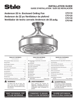
Unpack your fan and check the contents . You should have the following items:
A. Fan blades (5)
B. Canopy & Ceiling mounting bracket
C. Ball/downrod assembly
D. Coupling cover
E. Fan motor assembly
F. Set of 5 blade brackets and
Pre-Installed mounting screws
G. Light plate
H. Switch housing
I. Glass shade
J. CoolTouch
™
Receiver
K. Basic Function CoolTouch
™
Control System
L. Part bag contents
1) Mounting hardware:
wood screws (2), flat washers (2), star
washers (2), wire nuts (3), screws (2)
2) Blade attachment hardware :
screws (17), fiber washers (17)
3) Blade brackets hardware:
screws (2)
4) Safety cable hardware:
Wood screw, spring washer, flat washer
5) Balance kit
a
b
c
d
e
f
i
g
h
k
l
j
5
Cameron
™
|

MOUNTING OPTIONS
If there isn’t an existing UL (cUL for Canadian Installation) listed
mounting box, then read the following instructions. Disconnect the
power by removing fuses or turning o circuit breakers.
Secure the outlet box directly to the building structure. Use
appropriate fasteners and building materials. The outlet box and its
support must be able to fully support the moving weight of the fan
(at least 50 lbs). Do not use plastic outlet boxes.
Figures 1, 2 and 3 are examples of dierent ways to mount the
outlet box.
NOTE: If you are installing the ceiling fan on a sloped (vaulted)
ceiling, you may need a longer downrod to maintain proper
clearance between the tip of the blade and the ceiling. A minimum
clearance of 12” is suggested for optimal operation.
NOTE: Depending on the location you have selected for
installation, you may need to purchase and install a “Joist Hanger”
for the support of the outlet box. Make sure the joist hanger you
purchase has been designed for use with ceiling fans. (Fig. 4)
Outlet box
Fig. 1
Outlet box
Fig. 2
Fig. 3
Recessed
outlet box
Provide strong
support
Ceiling
mounting
plane
ANGLED CEILING
MAXIMUM 30° ANGLE
Fig. 4
Outlet box
6 | KICHLER.COM

HANGING THE FAN
REMEMBER to turn o the power before you begin. To properly install your ceiling
fan, follow the steps below.
Step 1. Remove the decorative canopy bottom cover from the canopy by turning
the cover counter clockwise. (Fig. 5)
Step 2. Remove the ceiling mounting bracket from the canopy by removing
(and save) one of the two screws. Loosen the remaining screw by a half turn.
(Fig. 5)
Step 3. Pass the 120 volt supply wires from the ceiling outlet box through the
center of the ceiling mounting bracket. (Fig. 6)
Step 4. Attach the ceiling mounting bracket to the outlet box using the screws
and washers included with the outlet box. (Fig. 6)
Step 5. Remove the hanger ball from the downrod assembly by loosening the set
screw, removing the cross pin and sliding the ball o the rod. (Fig. 7)
Fig. 5
Ceiling mounting bracket
Canopy
Canopy cover
Fig. 6
120V Wires
CUL Listed
outlet box
Washers
Hook
Mounting screws
(supplied with electrical box)
Ceiling
mounting
bracket
Fig. 7
Downrod
Set screw
Hanger ball
Cross pin
7
Cameron
™
|

HANGING THE FAN
Step 6. Loosen the two set screws and remove the hitch pin and retaining clip
from the coupling on top of the motor assembly. (Fig. 8)
Step 7. Carefully feed the electrical lead wires from the fan up through the
downrod. Thread the downrod into the coupling until the Hitch pin holes
are aligned.
Next, replace the hitch pin and retaining clip. Tighten both set screws. (Fig. 8)
Step 8. Slip the coupling cover, canopy cover and canopy onto the downrod.
Thread the hanger ball onto the downrod, insert the cross pin through the
downrod and tighten. Now tighten the set screw. (Fig. 9)
Fig. 9
Cross pin
Hanger ball
Hanger ball
Downrod
Coupling
Coupling cover
Canopy cover
Canopy
PL-190B
Fig. 8
Supply wires
Coupling
Set screw
Set screw
Retaining clipHitch pin
Downrod
8 | KICHLER.COM

HANGING THE FAN
Step 9. Lift the motor assembly into position and place the hanger ball into the
ceiling mounting bracket.
Rotate the entire assembly until the “Check Tab” has dropped into the
“Registration Slot” and seats firmly. (Fig. 10)
The entire motor assembly should not rotate (left or right) when seated properly.
WARNING: Failure to reattach the cross pin and seat the “Check Tab” can cause
the fan to fall from the ceiling during operation. Take special care to make sure this
pin is reattached.
Fig. 10
Check tab
Registration slot
9
Cameron
™
|

INSTALLATION OF SAFETY SUPPORT
(Required for Canadian installation ONLY)
A safety support cable is provided to help prevent the ceiling fan from falling,
please install it as follows.
Step 1. Attach the provided wood screw and washers to the ceiling joist next to the
mounting bracket but do not tighten. (Fig. 11)
Step 2. Adjust the length of the safety cable to reach the screw and washers by pulling the
extra cable through the cable clamp until the overall length is correct, put the end of the
cable back through the cable clamp, forming a loop at the end of the cable. Tighten the
cable clamp securely. Now, put the loop in the end of the safety cable over the wood screw
and under the washer. Tighten the wood screw securely.
NOTE: Although the safety support cable is required for Canadian installations only. It’s a
good idea to make the attachment with any installation.
Ceiling
mounting
bracket
Attach safety
cable to ceiling
joist with screw
and washer
Fig. 11
10 | KICHLER.COM

MAKE THE ELECTRIC CONNECTIONS
WARNING: To avoid possible electrical shock, be sure you have turned o the
power at the main circuit panel.
NOTE: In the Transmitter, Set Dip Switch #5 on the D position. This enables the
dimming function.
NOTE: The CoolTouch
™
Control System is equipped with 16 possible frequency
combinations to prevent interference from or with other remote control units.
The frequency switches on your receiver and transmitter have been preset at the
factory. Please recheck to make sure the switches on transmitter and receiver
are set to the same position, any combination of settings will operate the fan as
long as the transmitter and receiver are set to the same position. (Fig. 12)
Step 1. Insert the receiver into the ceiling mounting bracket with the flat side of
the receiver facing the ceiling. (Fig. 13) For best performance, make sure the Black
Antenna, on the end of the receiver, remains extended and not tangled with any
of the electrical wires.
Step 2. Motor to Receiver Electrical Connections: (Fig. 14) Connect the black wire
from the fan to the black wire marked “TO MOTOR L” on the receiver.
Fig. 13
ON
1 2 3 4
D
X
ON
Hanger
bracket
Receiver
Dip switch
Fig. 12
11
Cameron
™
|

MAKE THE ELECTRIC CONNECTIONS
FINISHING THE INSTALLATION
Connect the white wire from the fan to the white wire marked “TO MOTOR N” from the receiver.
Connect the blue wire from the fan to the blue wire marked “FOR LIGHT” from the receiver.
Secure all the wire connections with the plastic wire nuts provided.
Step 3. (Fig. 14) Receiver to House Supply Wires Electrical Connections: Connect the black
(hot) wire from the ceiling to the black wire marked “AC in L” from the receiver. Connect the
white(neutral) wire from the ceiling to the white wire marked “AC in N” from the Receiver. Secure
the wire connections with the plastic wire nuts provided.
Step 4. (Fig. 14) If your outlet box has a ground wire (green or bare copper) connect it to the fan
ground wires; otherwise connect the hanging bracket ground wire to the mounting bracket. Secure
the wire connection with a plastic nut provided. After connecting the wires, spread them apart so
that the green and white wires are on one side of the outlet box and black and blue wires are on the
other side. Carefully tuck the wire connections up into the outlet box.
NOTE: Fan must be installed at a maximum distance of 30 feet from the CoolTouch
™
Remote
Transmitter for optimal signal transmission between the transmitter and the fan’s receiving unit.
Step 1. Tuck all the connections neatly into the ceiling outlet box.
Step 2. Slide the canopy up to the mounting bracket and place one of the key hole slots over the
mounting screw on the mounting bracket. Rotate the canopy until the screw head locks in place at
the narrow section of the key hole. See figure 15.
Step 3. Align the remaining circular hole on the canopy with the remaining hole on the Ceiling
Mounting Bracket. Insert and tighten the mounting screw you removed earlier and the mounting
screw from Step 2 above. Now, attach the canopy cover to the mounting screw heads by inserting
the screw heads into the bottom side of the canopy cover and rotating the cover clockwise.
NOTE: Adjust the canopy screws as necessary until the canopy and canopy cover are snug. (Fig. 15)
Black (motor)
Blue (for light)
Receiver
Black (“to motor L”)
Black (“AC IN L”)
Black (hot)
Outlet box
(Connect to
ground wire on
hanger bracket if
no house ground
wire exists.)
Ground
(green)
White (“to motor N”)
White (“AC IN N”)
Green or bare
copper (ground)
White (neutral)
White (neutral)
Screws
Screws
Ceiling
mounting
bracket
Outlet box
Fig. 15
Fig. 14
Blue (for light)
Canopy cover
Canopy
12 | KICHLER.COM

ATTACHING THE FAN BLADES
Step 1. Attach a blade to a blade bracket using the screws and rubber washers provided.
(Fig.16)
Make sure the blade is straight when set on the blade bracket. Tighten each mounting
screw and then repeat this procedure for each blade.
Step 2. Attach each blade assembly to the motor using the “Pre-Installed” mounting
screws in the blade bracket. (Fig 16)
INSTALLING THE LIGHT PLATE
Step 1. Loosen the two screws on the mounting ring attached to the motor shaft
and “remove” and save the third screw. (Fig. 17)
Step 2. Place the key hole slots on the light plate over the two screws previously
loosened on the mounting ring.
Turn the light plate until is locks in place at the narrow section of the key hole slots.
Tighten both key hole screws and replace the third screw previously removed and
tighten securely.
Mounting ring
Screws
Light plate
Screws
Rubber
washers
Blade brackets
Screws
Blades
Fig. 16
Fig. 17
13
Cameron
™
|

INSTALLING THE LED LIGHT KIT
INSTALLING THE GLASS SHADE
NOTE: Before continuing installation, confirm that the power is still turned o at the
main circuit breaker or by removing the correct fuse. Turning the power o using a
wall switch is not sucient to prevent electrical shock.
Step 1. Loosen the two mounting screws on the inside of the light plate then remove
and save the third screw.
Hold the LED light kit close to the light plate and connect the white wires from the
socket plate and the fan by pushing the connectors together. Follow the same
procedure with the black wire connectors. (Fig. 18)
Step 2. Tuck the connections neatly into the light plate. Place the key holes on the
LED light kit over the 2 screws previously loosened from the light plate, turn the
LED light kit until it locks in place at the narrow section of the key holes. Secure by
tightening all three screws. (Fig. 18)
Raise the glass shade against the LED light kit and turn clockwise until snug, DO
NOT OVER TIGHTEN. (Fig. 19)
LED Light kit
Wire connectors
Light plate
Screws
Glass
shade
LED Light kit
Fig. 19
Fig. 18
14 | KICHLER.COM

INSTALLING THE BATTERIES
Remove the battery compartment cover on the back of the CoolTouch
™
Transmitter and insert both batteries provided. Make sure the + sign is facing up.
Take care during this procedure NOT TO move the frequency dip switches inside this
compartment. The settings MUST remain the same as the settings on the receiver for
proper communication with the control system.
It’s a good idea to remove these batteries if your fan is not used for extend periods of
time, (months).
NOTE: Make sure Dip Switch #5 is set to the D position. This enables the dimming function.
ON
1 2 3 4
D
X
ON
Fig. 20
Code Switch
15
Cameron
™
|

OPERATING INSTRUCTIONS
Restore power to ceiling fan and test for proper operation.
A. , , and buttons:
These three buttons are used to set the fan speed as follows:
= High speed
= Medium speed
= Low speed
B.
button:
This button turns the fan o.
C. The “
” button: turns the light fixture On/O or controls dimming.
Press and release for On or O, Press and HOLD for full range dimming.
NOTE: As stated above, the light dimming function on this control is operated by
holding down the light button and releasing it at the desired brightness level.
This control system is NOT designed to “Reverse” the rotation of the blades. To set
the fan blades in reverse, the reverse slide switch is located on the top of the Motor
Housing. See Fig. 22
Do not operate reversing switch while fan blades are in motion. Fan must be turned
o and blades stopped before reversing blade direction.
Fig. 22
Fig. 21
Slide Switch
16 | KICHLER.COM

OPERATING INSTRUCTIONS
Speed settings for warm or cool weather depend on factors such as
the room size. Ceiling height, number of fans and so on.
Warm Weather Operation: Forward (counter clockwise) A downward
airflow creates a cooling eect as shown in Fig. 23. This allows you to
set your air conditioner on a warmer setting without aecting your
general comfort.
Cool Weather Operation: Reverse (clockwise). An upward airflow
moves warm air o the ceiling areas as shown in Fig. 24. This allows
you to set your heating unit on a cooler setting without aecting your
general comfort.
Fig. 23
Fig. 24
17
Cameron
™
|

INSTALLING THE COOLTOUCH
™
CONTROL SYSTEM WALL PLATE
NOTE: All wiring must be in accordance with the National Electrical
Code and local electrical codes. Electrical installation should be
performed by a qualified licensed electrician.
Select a location to install your CoolTouch
™
Control System
Transmitter. You can replace an existing wall switch or, install the
transmitter on ANY flat surface.
Option 1: Install the control system using an existing wall switch
outlet box. Make sure the electrical power is TURNED OFF at the
main panel before continuing.
NOTE: Switch installation must comply with all local and national
electric code.
Step 1. Remove the existing wall plate and the old switch from the
wall outlet box. Wire nut the BLACK leads (hot) together and push
back inside the outlet box. (Fig. 25)
Step 2. Install the metal plate and CoolTouch™ wall plate to the
existing wall outlet box with 4 screws provided. Then place the two
plastic plugs into the wall plate. (Fig. 26)
Option 2: Install the control system on ANY flat surface.
Select the desired location and use the CoolTouch
™
wall plate to
mark the location for the mounting holes. Use the dry wall anchors
and/or screws provided and finish the installation.
Metal plate
Outlet box
CoolTouch™ wall plate
Plastic plugs
Screws
Screws
Outlet box
Switch
Wall plate
Fig. 26
Fig. 25
18 | KICHLER.COM

INSTALLING THE TRANSMITTER
1. Insert the transmitter into the wall plate by inserting the bottom
of the transmitter first and then press the top of the transmitter into
the pocket. The transmitter will fully function from this location or
you can remove the transmitter and use as a “Hand Held” device.
2. To remove the transmitter from the wall plate, push the release
button and the transmitter will fall into your hand.
Release
button
Fig. 27
19
Cameron
™
|

TROUBLESHOOTING
Problem Solution
Fan will not start. 1. Check circuit fuses or breakers.
2. Check all electrical connections to ensure proper contact. CAUTION: Make sure the main
power is OFF when checking any electrical connection.
3. Make sure the transmitter batteries are installed properly. Positive (+) side facing out.
4. Ensure the batteries have a good charge.
Fan sounds noisy. 1. Make sure all motor housing screws are snug.
2. Make sure the screws that attach the fan blade brackets to the motor are tight.
3. Make sure wire nut connections are not rubbing against each other or the interior wall of the
switch housing. CAUTION: Make sure main power is o.
4. Allow a 24-hour “breaking-in” period. Most noise associated with a new fan disappear during
this time.
5. If using an optional light kit, make sure the screws securing the glassware are tight. Make sure
the light bulbs are not touching any other component.
6. Do not connect this fan to wall mounted variable speed control(s). they are not compatible
with ceiling fan motors or remote controls.
7. Make sure the upper canopy is a short distance from the ceiling. It should not touch the
ceiling.
20 | KICHLER.COM
/