NOMA Landon Indoor Le manuel du propriétaire
- Catégorie
- Ventilateurs ménagers
- Taper
- Le manuel du propriétaire

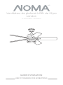
Landon
52” LED Ceiling Fan
PRODUCT NO. 052-9608-8
USER MANUAL
READ AND SAVE THESE INSTRUCTIONS

TABLE OF CONTENTS

3
01. SAFETY/CAUTIONS
02. TOOLS REQUIRED
03. EXPLODED VIEW
04. ELECTRICAL SAFETY
05. ASSEMBLY
06. OPERATION
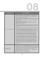
08. TROUBLESHOOTING
07. DYNAMIC BLADE BALANCING KIT
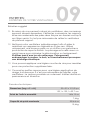
09. MAINTENANCE
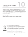
10. WARRANTY & DISPOSAL
4
6
7
10
12
19
22
24
26
27

4
SAFETY / CAUTIONS
•
•
•
•
•
•
•
•
•
•
TO REDUCE THE RISK OF ELECTRIC SHOCK, ENSURE ELECTRICITY HAS
BEEN TURNED OFF AT THE CIRCUIT BREAKER OR FUSE BOX BEFORE
BEGINNING.
ALL WIRING MUST BE IN ACCORDANCE WITH THE NATIONAL AND
LOCAL ELECTRICAL CODES. ELECTRICAL INSTALLATION SHOULD BE
PERFORMED BY A QUALIFIED LICENSED ELECTRICIAN.
WARNING: TO REDUCE THE RISK OF ELECTRIC SHOCK OR FIRE, DO
NOT USE THIS FAN WITH ANY SOLID-STATE FAN-SPEED CONTROL DEVICE.
IT WILL PERMANENTLY DAMAGE THE ELECTRONIC CIRCUITRY.
CAUTION: TO REDUCE THE RISK OF PERSONAL INJURY, USE ONLY THE
SCREWS PROVIDED WITH THE OUTLET BOX.
THE OUTLET BOX AND SUPPORT STRUCTURE MUST BE SECURELY
MOUNTED AND CAPABLE OF RELIABLY SUPPORTING A MINIMUM OF
35 LB (15.9 KG). USE ONLY UL LISTED OUTLET BOXES MARKED “FOR FAN
SUPPORT.”
THE FAN MUST BE MOUNTED WITH A MINIMUM OF 6’ 11” (2.1 M) FROM
THE TRAILING EDGE OF THE BLADES TO THE FLOOR.
DO NOT PLACE OBJECTS IN THE PATH OF THE BLADES.
TO AVOID PERSONAL INJURY OR DAMAGE TO THE FAN AND OTHER
ITEMS BE CAUTIOUS WHEN WORKING AROUND OR CLEANING THE FAN.
DO NOT USE WATER OR DETERGENTS WHEN CLEANING THE FAN OR
FAN BLADES. A DRY DUST CLOTH WILL BE SUITABLE FOR MOST
CLEANING.
AFTER MAKING ELECTRICAL CONNECTIONS, SPLICED CONDUCTORS
SHOULD BE TURNED UPWARD AND PUSHED CAREFULLY UP INTO THE
OUTLET BOX. THE WIRES SHOULD BE SPREAD APART WITH THE GROUNDED
CONDUCTOR AND THE EQUIPMENT-GROUNDING CONDUCTOR ON ONE
SIDE OF THE OUTLET BOX AND THE UNGROUNDED CONDUCTOR ON THE
OTHER SIDE OF THE OUTLET BOX. ALL SET SCREWS MUST BE CHECKED AND
RE-TIGHTENED WHERE NECESSARY BEFORE INSTALLATION.

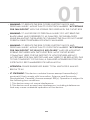
01
•
•
•
•
•
WARNING: TO REDUCE THE RISK OF FIRE, ELECTRIC SHOCK AND
PERSONAL INJURY, MOUNT FAN TO OUTLET BOX MARKED “ACCEPTABLE
FOR FAN SUPPORT” WITH THE SCREWS PROVIDED WITH THE OUTLET BOX
WARNING: TO AVOID RISK OF PERSONAL INJURY, DO NOT BEND THE
BLADE ARMS (ALSO REFERRED TO AS FLANGES) OR THE BRACKETS
WHILE BALANCING THE BLADES OR CLEANING THE FAN. DO NOT INSERT
FOREIGN OBJECTS BETWEEN ROTATING FAN BLADES.
WARNING: TO REDUCE THE RISK OF FIRE, ELECTRIC SHOCK AND
PERSONAL INJURY, MOUNT FAN TO OUTLET BOX MARKED “ACCEPTABLE
FOR FAN SUPPORT” OF 35 LB (15.9 KG) OR LESS” AND USE MOUNTING
SCREWS PROVIDED WITH THE OUTLET BOX. MOST OUTLET BOXES
COMMONLY USED FOR THE SUPPORT OF LIGHT FIXTURES ARE NOT
ACCEPTABLE FOR FAN SUPPORT AND MAY NEED TO BE REPLACED. DUE
TO THE COMPLEXITY OF THIS FAN, A QUALIFIED LICENSED ELECTRICIAN
IS STRONGLY RECOMMENDED FOR INSTALLATION.
ATTENTION: PLEASE ENSURE LED BULBS’ TOTAL WATTAGE IS ALWAYS
BELOW 70 W!
IC STATEMENT: This device contains license-exempt transmitter(s)/
receiver(s) that comply with lnnovation, Science and Economic
Development Canada’s license-exempt RSS(s). Operation is subject to
the following two conditions:
1. This device may not cause interference.
2. This device must accept any interference, including interference
that may cause undesired operation of the device.
5

6
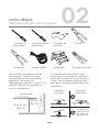
02
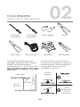
TOOLS REQUIRED
INSTALLATION PREPARATION
Flat-head
screwdriver
Cross-head
screwdriver
Safety glasses Pliers
Wire cuttersElectrical tape Stepladder Wire strippers
To prevent personal injury and
damage, ensure that the hanging
location allows the blades a
clearance of 6’ 11” (2.1 m) from the
obstruction.
6' 11"
(2.1 m)
30”
(76 cm)
blade edge downrod
installation installation
vaulted
ceiling angle
is not to
exceed 18°
This fan can be mounted with a
downrod on a regular (no-slope) or
vaulted ceiling. Other installations,
such as flush mount, are not
available for this fan.

7
03
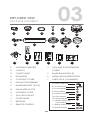
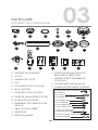
EXPLODED VIEW
PACKAGE CONTENTS
Installation
Instruction
01.
02.
03.
04.
05.
06.
07.
08.
09.
10.
11.
12.
13.
01 02
08
12 13 14 15 16 17
03 04
09 10 11
05 06
07
MOUNTING BRACKET
CANOPY
CANOPY RING
DOWNROD
COUPLING COVER
FAN MOTOR ASSEMBLY
BLADE BRACKETS (5 PCS)
FAN BLADES (5 PCS)
MOUNTING PLATE
20 W LED LIGHT KIT
GLASS SHADE
RECEIVER
REMOTE CONTROL
14.
15.
16.
17.
2-PIN AND 3-PIN EXTENSION
CORDS
BLADE BALANCING KIT
INSTALLATION INSTRUCTIONS
PARTS PACK CONTAINING:
1
2
3
4
5
6
1H 3 6H H
x16
x11
11 x Blade screws with
lock washer
3 x plastic wire nuts
2 x wood screws
3 x Lock washers
2 x Machine screws
1 x Safety cable screw
3 x Flat washers
16 x Flat washers
16 x Fiber washers
5 x Screw retainer

01.
02.
03.
04.
05.
06.
07.
08.
09.
10.
11.
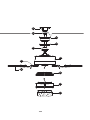
MOUNTING BRACKET
DOWNROD
CANOPY
CANOPY RING
COUPLING COVER
FAN MOTOR ASSEMBLY
BLADE BRACKETS (5 PCS)
FAN BLADES (5 PCS)
MOUNTING PLATE
20 W LED LIGHT KIT
GLASS SHADE
8
EXPLODED VIEW
DETAIL 03

9
08
07
03
04
06
09
10
11
01
02
05

10
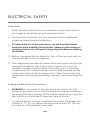
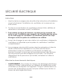
ELECTRICAL SAFETY
Instructions
•
01.
02.
03.
04
Making the Electrical Connections
•
•
Read all safety information and installation instructions before
you begin to install the fan and save instructions.
All set screws of the fan must be checked and re-tightened
where necessary before installation.
To reduce the risk of personal injury, do not bend the blade
brackets when installing the brackets, balancing the blades or
cleaning the fan. Do not insert foreign objects between rotating
fan blades.
Before changing the fan direction, turn off the fan and wait for
the fan blades to stop completely.
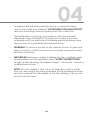
The safeguards provided by these safety instructions and by the
separate installation instructions are not meant to cover all
possible conditions and situations that may occur. It must be
understood that common sense, caution and care are factors
which can not be built into this product. These factors must be
supplied by the person(s) installing, caring for and operating the
fan.
WARNING: To avoid risk of electric shock, be sure to shut off
power at the main fuse or circuit breaker box before installing or
servicing this fixture. Turning off the electrical power by using the
light switch is not sufficient to prevent electric shock.
To reduce the risk of injury, install the fan so that the blades are
at least 6’ 11” (2.1 m) above the floor and at least 30” (76 cm)
from the tip of the blades to the wall.

To reduce the risk of fire, electric shock, or personal injury,
mount the outlet box marked “ACCEPTABLE FOR FAN SUPPORT”
and use mounting screws provided with the outlet box.
The installation must be in accordance with the national
electrical code, ANSI/NFPA 70 and local codes. If you are
unfamiliar with the methods of installing electrical wiring, seek
the services of a qualified licensed electrician.
WARNING: To reduce the risk of fire, electric shock, or personal
injury, mount to outlet box and use mounting screws provided
with the outlet box.
IMPORTANT: Before you begin installing the fan, carefully read
all information on the separate sheet “SAFETY INSTRUCTIONS”
as well as the following “Installation Steps”. If in doubt, consult a
qualified electrician.
NOTE: The fan weight is 16 lb 12 oz (7.6 kg). Be sure the outlet
box you are using is securely attached to the building structure
and can support the full weight of the fan. Failing to do so can
result in serious injury.
04
•
•
•
•
•
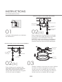
11

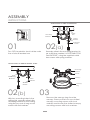
Turn OFF the electric circuit at the main
fuse of circuit breaker box
01 02(a)
02(b) 03
ASSEMBLY
INSTRUCTIONS
12
Securely attach the mounting bracket to
an outlet box marked “ACCEPTABLE FOR
FAN SUPPORT” using the supplied outlet
box screws with spring washers.
With two mounting holes in the
ceiling joist, securely attach the
mounting bracket to the ceiling,
using the two sets of long wood
screws with flat washers.
INSTALLING TO THE OUTLET BOX
Outlet
Box
Mounting
Bracket
Outlet Box
Screw
Spring
Washer
INSTALLING TO THE BUILDING JOIST
Flat
Washer
Mounting
Bracket
Wood
Screw
Canopy
Canopy
ring
Mounting
Bracket
Screws
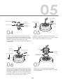
Remove the canopy ring from the
canopy. Remove the two non-slotted
canopy mounting screws with lock
washers and loosen the slotted canopy
mounting screws with lock washers.

13
05
06 07
04 05
Canopy
Ring
Canopy
Coupling
Cover
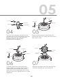
Take out the setscrew located in the
hanger ball, lower the hanger ball and
remove the cross pin. Remove the
hanger ball from the hanger
ball/downrod assembly.
Downrod
Hanger Ball
Setscrew
Cross Pin
Remove the clevis pin and cotter pin,
and loosen the two collar setscrews from
the motor collar.
Cotter pin
Setscrews
Clevis pin
Carefully feed the motor wires and
safety cable up through the downrod.
Thread the downrod into the collar.
Align the holes and replace the cotter
pin and clevis pin. Tighten the two collar
setscrews.
Setscrews
Cotter pin
Clevis pin
Downrod
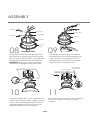
Slip the coupling cover, the canopy ring,
and the canopy onto the downrod.

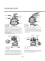
ASSEMBLY
14
10 11
08 09
Canopy
Ring
Canopy
Hanger Ball
Canopy
Ring
Canopy
Downrod
Hanger Ball
Setscrew
Cross Pin
Carefully reinstall the hanger ball onto
the downrod, being sure that the cross
pin is in the correct position, the setscrew
is tightened and wires are not twisted.
WARNING: Ensure no wire is pinched,
twisted or damaged during this step.
If a longer downrod (not included) is
needed, be sure to snap together the
2-pin and 3-pin connectors, the two
male plugs from the fan and female
plugs from the extension cord.
Secure the safety cable to the building
structure using a wood screw and
washers.
Carefully lift the fan motor assembly up
to the mounting bracket. Make sure the
tab on the mounting bracket socket is
properly seated in the groove in the
hanger ball/downrod assembly.
Groove
Tab
Safety Cable
Ceiling
Wood Screw
And Washer

15
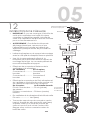
05
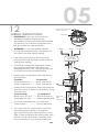
12
WIRING INSTRUCTIONS
•
•
•
•
•
•
•
•
IMPORTANT: If you are not sure if the
electrical outlet box and fan are
grounded, contact a licensed electrician
for advice. The outlet box and fan must
be grounded for safe operation.
WARNING: To avoid possible electric
shock, be sure electricity is turned off at
the main fuse box before wiring.
Insert the receiver into the mounting
bracket with the flat side of the receiver
facing the ceiling.
2-pin and
3-pin
connectors
Black White
Ground
conductor
Outlet Box
Mains cables
White
Black
Green
Green
Green
Green
Once the connection has been made,
the receiver inserts into the drop rod
hanging bracket. The canopy comes up
to cover the receiver and bracket.
Make wire connections from the fan to
the receiver.
From fan To receiver
2-pin connector----------2-pin connector
3-pin connector----------3-pin connector
Make wire connections from the receiver
and fan to the outlet box as follows, using
the wire nuts.
From receiver To outlet box
Black wire "AC in L" -------Black wire (hot)
White wire "AC in N" ----------White wire (neutral)
From fan and receiver to outlet box
Green wires --------------- Green (ground)
Turn the wire nut connections upward,
spreading them apart so the green
(ground) and white wires will be on one
side of the outlet box and the black wire
will be on the other side. Carefully tuck
the connections up into the outlet box.
Leave unconnected
and do not cut.
Receiver

16
15 16
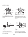
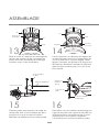
Attach the blades to the blade brackets
using the three blade attachment
screws and fiber washers. Make sure the
blade is straight. Repeat these steps for
the remaining blades.
Attach two blade bracket screws and
lock washer to the blade brackets by
using the screw retainer to keep the
screws in place. Repeat for all remaining
blades.
Blade Brackets
Screws and
Fiber Washers
Fan Blade
ASSEMBLY
13
Secure the canopy to the mounting
bracket with the four canopy mounting
screws with lock washers included with
your fan.
14
Raise up canopy ring and line up the
four grooves with the four screw heads
on the canopy. Once lined up, slide the
canopy ring and secure it to the canopy
by turning the canopy ring clockwise
until snug.
Canopy
Screws
Screws
Mounting
Bracket
Canopy
Canopy
Ring
Screws
Screws
Grooves
Blade
Brackets
Screws with
Lock Washers
Screw
Retainer

17
05
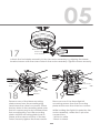
17
19
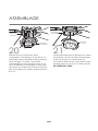
Remove one of the three mounting
plate screws from the mounting ring
and loosen the other two screws. Place
the key holes in the mounting plate over
the two screws previously loosened from
the mounting ring. Turn the mounting
plate until the mounting plate locks in
place at the narrow section of the key
holes. Securely tighten the three screws.
Remove one of the three light kit
mounting screws from the mounting
plate and loosen the other two screws.
While holding the light kit under the fan
motor assembly, make the 2-pin wire
connections:
- White to white
- Black to black
Mounting
Plate
Screws
Mounting
Ring
Light Kit
Screws
Mounting
Plate
Wire
Connectors
18
Attach the fan blade assembly to the fan motor assembly by aligning the blade
bracket screws with the screw holes in the motor assembly. Tighten screws securely.
Screws with
Lock Washers
Blade Brackets

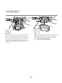
18
21
Carefully lift the glass shade up inside the
LED light kit and secure it to the fan by
turning the glass shade clockwise until
snug. DO NOT OVERTIGHTEN.
Place the key holes in the light kit over
the two screws previously loosened
from the mounting plate. Turn the light
kit clockwise until the light kit locks in
place at the narrow section of the key
holes. Securely tighten the three
screws.
20
Light Kit
Screws
Mounting
Plate
Light Kit
Glass
Shade
ASSEMBLY

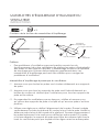
19
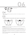
06
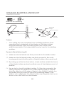
OPERATION
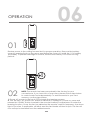
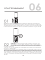
01
Restore power to the ceiling fan and test for proper operation. Remove the battery
cover by pressing firmly on the arrow and sliding the cover off. Install the 1.5 V battery
(included). To prevent damage to remote, remove the battery if not used for long
periods.
02 NOTE: The remote has been pre-paired in the factory for your
convenience. If you have two or more fans, please follow steps below
to control each fan independently. To add a remote to your fan’s
memory, use the steps below:
1. Ensure AC power to the fan is OFF to begin the learning process.
2. Turn the fan’s AC power ON. Within 60 seconds of turning AC power on, press and
release the "LEARN" button located in the remote's battery compartment to enter the
learning function. Once the fan has detected the remote control's frequency, the down
light of your fan, if applicable, will blink, and the fan blades will start to spin. The fan will
now accept commands from the added remote.
LEARN

20
OPERATION
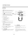
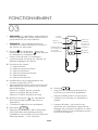
03
NOTE: The fan will store the last used speed
setting for the next time it is turned on.
NOTE: You must turn the fan on prior to
using the speed or time functions.
Fan button - Press and release the
button to turn the fan on or off.
When turned on, the fan will begin
spinning using its last speed settings.
Speed functions
1 = Low speed
2 = Medium low speed
3 = Medium speed
4 = Medium high speed
5 = High speed
6 = Extra high speed
Correlated Colour Temperature (CCT)
changing
Push and release the button to cycle
through the five colour temperature
options.
Option 1: 3000K (Soft White)
Option 2: 4000K (Bright White)
Option 3: 5000K (Daylight)
Fan reverse botton (Must be pushed
when the fan is in operation)
Controls fan direction.
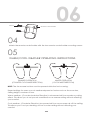
Timer
Pressing the timer button will automatically
turn fan and light (if light is on) off after 1,
3, or 6 hours.
Signal Light
Timer
Light Dimmer
Fan Reverse
Fan speed
1
2
3
4
5
6
1H 3 6H H
Correlated Colour
Temperature (CCT)
changing
Power on/off
•
•
•
•
•
•
1.
2.
3.
4.
5.
Light
Press and hold the button to activate
the dimmer function.
Press and release the light button to turn
the light on or off.
Light on: The fan memory function will
resume the light setting (on or off and
dim) on the fan prior to the power being
turned off.
•
•
•
6.
1H 3 6H H
La page est en cours de chargement...
La page est en cours de chargement...
La page est en cours de chargement...
La page est en cours de chargement...
La page est en cours de chargement...
La page est en cours de chargement...
La page est en cours de chargement...
La page est en cours de chargement...
La page est en cours de chargement...
La page est en cours de chargement...
La page est en cours de chargement...
La page est en cours de chargement...
La page est en cours de chargement...
La page est en cours de chargement...
La page est en cours de chargement...
La page est en cours de chargement...
La page est en cours de chargement...
La page est en cours de chargement...
La page est en cours de chargement...
La page est en cours de chargement...
La page est en cours de chargement...
La page est en cours de chargement...
La page est en cours de chargement...
La page est en cours de chargement...
La page est en cours de chargement...
La page est en cours de chargement...
La page est en cours de chargement...
La page est en cours de chargement...
La page est en cours de chargement...
La page est en cours de chargement...
La page est en cours de chargement...
La page est en cours de chargement...
La page est en cours de chargement...
La page est en cours de chargement...
La page est en cours de chargement...
La page est en cours de chargement...
-
 1
1
-
 2
2
-
 3
3
-
 4
4
-
 5
5
-
 6
6
-
 7
7
-
 8
8
-
 9
9
-
 10
10
-
 11
11
-
 12
12
-
 13
13
-
 14
14
-
 15
15
-
 16
16
-
 17
17
-
 18
18
-
 19
19
-
 20
20
-
 21
21
-
 22
22
-
 23
23
-
 24
24
-
 25
25
-
 26
26
-
 27
27
-
 28
28
-
 29
29
-
 30
30
-
 31
31
-
 32
32
-
 33
33
-
 34
34
-
 35
35
-
 36
36
-
 37
37
-
 38
38
-
 39
39
-
 40
40
-
 41
41
-
 42
42
-
 43
43
-
 44
44
-
 45
45
-
 46
46
-
 47
47
-
 48
48
-
 49
49
-
 50
50
-
 51
51
-
 52
52
-
 53
53
-
 54
54
-
 55
55
-
 56
56


NOMA Landon Indoor Le manuel du propriétaire
- Catégorie
- Ventilateurs ménagers
- Taper
- Le manuel du propriétaire
dans d''autres langues
- English: NOMA Landon Indoor Owner's manual
Documents connexes
-
NOMA Bower Indoor Le manuel du propriétaire
-
-
-
-
-
-
-
-
-
Autres documents
-
 Kichler Lighting Jade 300030 Manuel utilisateur
-
Kichler 310155SBK Manuel utilisateur
-
 Kichler Lighting 339501AP Manuel utilisateur
-
 Kichler Lighting 330017SNB Manuel utilisateur
-
Kichler Lighting 330016SNB Manuel utilisateur
-
 Kichler Lighting Motu Manuel utilisateur
-
 Kichler Lighting 310204WCP Manuel utilisateur
-
 Kichler Lighting 300200PN Manuel utilisateur
-
Fanimation FP8533PN Le manuel du propriétaire
-
for Living 5-blade 3-Speed Le manuel du propriétaire


