Fanimation FP8533PN Le manuel du propriétaire
- Catégorie
- Ventilateurs ménagers
- Taper
- Le manuel du propriétaire

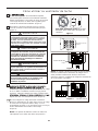
Serial Number
Purchase Date
™
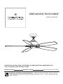
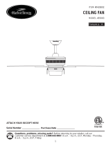
DOREN CEILING FAN
MODEL #FP8533**
Español p. 19
Questions, problems, missing parts? Before returning to your retailer, call our customer
service department at 1-888-567-2055, 8 a.m.-5 p.m., EST, Monday-Friday.
Net Weight 18.52 lbs (8.4 kg)
ATTACH YOUR RECEIPT HERE AND REGISTER YOUR FAN AT FANIMATION.COM
READ AND SAVE THESE INSTRUCTIONS

LIMITED LIFETIME MOTOR WARRANTY - If any part of your fan motor fails, due to a defect in materials or workmanship during 1.
the lifetime of the original purchaser, Fanimation will provide the replacement part free of charge, when the defective fan is returned
to our national service center. Proof of purchase is required. Customer shall be responsible for all costs incurred in the removal or
reinstallation and shipping of the product for repairs or replacement.
ONE YEAR MOTOR LABOR WARRANTY - If your fan motor fails at any time within one year from the original purchase, due to defects 2.
in materials or workmanship, labor to repair the motor will be provided free of charge at our national service center. Purchaser will
be responsible for labor charges after this one-year period. Customer shall be responsible for all costs incurred in the removal or
reinstallation and shipping of the product for repairs or replacement.
If any other part of your fan fails at any time within one year after original purchase, due to a defect in materials or workmanship, we will 3.
repair, or replace, at our option, the defective part free of charge for parts and labor performed at our national service center.
Because of varying climate conditions, this warranty does not cover changes in the finish, including rusting, pitting, corroding, tarnishing, 4.
or peeling.
This
warranty is void and does not apply to damage from improper installation, neglect, accident, misuse, exposure to extremes of heat 5.
or humidity, or as a result of any modification to the original product.
All costs of removal and reinstallation of the fan are the sole responsibility of the owner of the fan and not the store that sold the fan 6.
or Fanimation.
Fanimation reserves the right to modify or discontinue any product at any time and may substitute any part under this warranty.7.
Under no circumstances may a fan be returned without prior authorization from Fanimation. The receipt of purchase must accompany 8.
authorized returns and must be sent freight prepaid to Fanimation. The fan to be returned must be properly packed to avoid damage
in transit; Fanimation will not be responsible for any damage resulting from improper packaging.
It is understood that any repair or replacement is the exclusive remedy available from Fanimation. There is no other expressed or 9.
implied warranty. Fanimation hereby disclaims any and all implied warranties, including, but not limited to those of merchantability and
fitness for a particular purpose to the extent permitted by law. Some states do not allow limitations on implied warranties. Fanimation
will not be liable for incidental, consequential, or special damages arising out of or in conjunction with product use or performance,
except as may otherwise be accorded by law. This warranty gives you special legal rights and you may also have other rights that
vary from state to state.
A certain amount of wobble is normal and should not be considered a problem or a defect.10.
LIMITED LIFETIME WARRANTY
Extends to the original purchaser of a Fanimation Fan
Important Safety Instructions
WARNING: To avoid fire, shock and serious personal injury, follow these instructions.
Table of Contents
Unpacking Instructions . . . . . . . . . . . . . . . . . . . . . . . . . . . . . . . . . . . . . . .3
(QHUJ\(I¿FLHQW8VHRI&HLOLQJ)DQV ............................4
(OHFWULFDODQG6WUXFWXUDO5HTXLUHPHQWV ..........................4
How to $VVHPEOH YRXU&HLOLQJ)DQ .............................6
How to Hang YRXU&HLOLQJ)DQ .................................8
How to Wire <RXU&HLOLQJ)DQ . . . . . . . . . . 9
+RZWR,QVWDOO<RXU&DQRS\+RXVLQJ . . . . . . . . . . . . . . . . . .10
Read your owner’s manual and safety information before installing your new fan. Review the accompanying assembly diagrams.1.
Before servicing or cleaning unit, switch power off at service panel and lock service panel disconnecting means to prevent power 2.
from being switched on accidentally. When the service disconnecting means cannot be locked, securely fasten a warning device,
such as a tag, to the service panel.
Be careful of the fan and blades when cleaning, painting, or working near the fan. Always turn off the power to the ceiling fan 3.
before servicing.
Do not insert anything into the fan blades while the fan is operating.4.
Do not operate reversing switch until fan blades have come to a complete stop.5.
Additional Safety Instructions
To avoid possible shock, be sure electricity is turned off at the fuse box before wiring, and do not operate fan without blades.1.
All wiring and installation procedures must satisfy National Electrical Codes (ANSI/ NFPA 70) and Local Codes. The ceiling fan 2.
must be grounded as a precaution against possible electrical shock. Electrical installation should be made or approved by a licensed
electrician.
The fan base must be securely mounted and capable of reliably supporting at least 35 lbs. See page 4 of owner’s manual for support 3.
requirements. Consult a qualified electrician if in doubt.
The fan must be mounted with the fan blades at least 7 feet from the floor to prevent accidental contact with the fan blades.4.
Follow the recommended instructions for the proper method of wiring your ceiling fan. If you do not have adequate electrical 5.
This fan is to be used in dry locations only.6.
knowledge or experience, have your fan installed by licensed electrician.
W$51,1* This product is designed to use only those parts supplied with this product and/or accessories designated specifically for
use with this product. Using parts and/or accessories not designated for use with this product could result in personal injury or property
damage.
W$51,1* To reduce the risk of personal injury, do not bend the blade bracket (flange or blade holder) when installing the brackets,
balancing the blades, or cleaning the fan. Do not insert foreign objects in between rotating fan blades.
W$51,1* To Reduce The Risk Of Fire Or Electric Shock. Do Not Use This Fan With Any Solid-State Speed Control Device.
W$51,1* To Reduce The Risk Of Electric Shock. Disconnect The Electrical Supply Circuit To The Fan Before Installing Light Kit.
+RZWR2SHUDWH<RXU&HLOLQJ)DQ ..........................13
Maintenance...............................................14
14
14
16
15Parts List . . . . . . . . . . . . . . . . . . . . . . . . . . . . . . . . . . . . . . . . . . . . . . . . . .
. . . . . . . . . . . . . . . . . . . . . . . . . . . . . . . . . . . . . . . . . . . .
([SORGHG9LHZ,OOXVWUDWLRQ. . . . . . . . . . . . . . . . . .
TURXEOHVKRRWLQJ 17
+RZWR&OHDQ<RXU&HLOLQJ)DQ%ODGHV . . . . . . . . . . . . . . . . . . . . . . . . .
How to .......... 10. . . . . . . . .+RZWR$VVHPEOH<RXU&HLOLQJ)DQ%ODGHV
+RZWR$VVHPEOH<RXU/LJKW.LW$VVHPEO\ . . . . . . . . . .11
+RZWR,QVWDOO<RXU5HPRWH&RQWURO. . . . . . . . . . . . . . . . . . . . . . . . . . . .

3
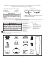
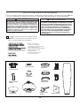
Unpacking Instructions
For your convenience, check-off each step. As each step is completed, place a check mark. This will ensure that all
VWHSVKDYHEHHQFRPSOHWHGDQGZLOOEHKHOSIXOLQ¿QGLQJ\Rur place should you be interrupted.
NOTE: If you are uncertain of part description, refer to
exploded view illustration.
1. Check to see that you have received the IROORZLQJ
parts:
Motor Assembly
+DQJHU%UDFNHW$VVHPEO\
'RZQURG+DQJHU%DOO
Assembly
&HLOLQJ&DQRS\
Canopy Screw Cover Assembly
0RWRU&RXSOLQJ&RYHU$VVHPEO\
%ODGH+ROGHU6HW
/LJKW3ODWH$VVHPEO\
/LJKW.LW*ODVV$VVHPEO\
%ODGH6HW
Receiver Unit
Hand-held Remote
W
ARNING
Do not install or use fan if any part is damaged or
missing. This product is designed to use only those
parts supplied with this product and/or any accessories
designated specifically for use with this product by
Fanimation. Substitution of parts or accessories not
designated for use with this product by Fanimation could
result in personal injury or property damage. Contact
your retail store for missing or damaged parts.
Light Kit/Glass
Assembly
ardware DJV
(OHYHQÝ3DQ+HDG6FUHZV
(blade holder to fan motor hub)
–
6L[WHHQÝ:DVKHU+HDG
Screws (blade to blade holder)
–
%DJ$VVHPEO\6DIHW\&DEOH–
6L[WHHQ)LEHU:DVKHUV –
– our ire Connectors
ZLWK/RFN:DVKHUV
Hardware BagsCeiling Canopy
Hanger Bracket
Assembly
Downrod/Hanger
Ball Assembly
Motor Assembly Blade Holder Set
Blade Set
Motor Coupling
Cover Assembly
Canopy Screw
Cover Assembly
This manual is designed to make it as easy as possible for you to assemble,
install, operate and maintain your ceiling fan
Tools Needed for Assembly
ne hillips head screwdriver
One stepladder
Four wire connectors
Before assembling your ceiling fan, refer to section
on proper method of wiring your fan (page 9). If you
feel you do not have enough wiring knowledge or
experience, have your fan installed by a licensed
electrician.
WARNING
!
One wire stripper
One
lade
screwdriver
nstalled ire HQJWK
ire i e
p to ft
ft
Materials
LULQJRXWOHW o and o connectors ust e of type
re
uired y the local code he ini u wire would e a
conductor ZLUHZLWKJURXQG RIWKHIROORZLQJVL e:
NOTE:
Place the parts from the loose parts bags in a small
container to keep them from being lost. If any parts are
missing contact your local retailer.
Light Plate Assembly
Hand-held
Remote
Receiver
Unit

4
Energy Efficient Use of Ceiling Fans
Ceiling fan performance and energy savings rely
heavily on the proper installation and use of the ceiling
fan. Here are a few tips to ensure efficient product
performance.
Turn Off When Not in the Room
Ceiling fans cool people, not rooms. If the room is
unoccupied, turn off the ceiling fan to save energy.
Using the Ceiling Fan Year Round
Summer Season: Use the ceiling fan in the counter-
clockwise direction. The airflow produced by the ceiling
fan creates a wind-chill effect, making you “feel” cooler.
Select a fan speed that provides a comfortable breeze,
lower speeds consume less energy.
WinterSeason: Reversethe motor andoperatethe ceiling
fan at low speed in the clockwise direction. This produces
a gentle updraft, which forces warm air near the ceiling
down into the occupied space.Remember to adjust your
thermostat when using your ceiling fan - additional energy
and dollar savings could be realized with this simple step!
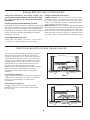
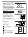
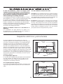
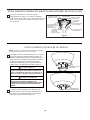
Electrical and Structural Requirements
Your new ceiling fan will require a grounded electrical
supply line of 120 volts AC, 60 HZ, 15 Amp Circuit.
Electrical code requires use of a fan-rated outlet box to
support the extra weight and motion associated with a
ceiling fan. A fan-rated box will be labeled as such and
typically supports up to a 70lb ceiling fan. Fan-Rated
Outlet Boxes vary in ratings and design. Ensure the
ratings of your ceiling fan outlet box meet the
requirements for the ceiling fan being installed. Figure 1,
Figure 2 and Figure 3 depicts different structural
configurations that may be used for mounting the
outlet box.
Low-profile use (Figure 1)
A 1
2-in.-deep pancake box is meant to be screwed to a
joist or block. It’s used if only one cable is coming into
the box. It is also available in a saddle-mount
configuration.
CEILING
2" x 4"
CEILING JOIST
OUTLET BOX
Figure 1
Figure 2
2" x 4"
CEILING JOIST
CEILING
OUTLET BOX
Deep-profile use (Figure 2)
A 2-1
-in.-deep box can be attached to blocking
between joists and is roomy enough to handle more
than one cable.
Choosing the Appropriate Mounting Location
Ceiling fans should be installed, or mounted, in the middle
of the room and at least 7 feet from floor to the blade and
18 inches from wall to the blade. If ceiling height allows,
install the fan 8 - 9 feet from floor to the blade for optimal
airflow. Consult your Fanimation Retailer for optional
mounting accessories.

5
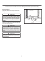
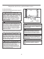
Electrical and Structural Requirements (Continued)
If your fan is to replace an existing light fixture, turn
electricity off at the main fuse box at this time and
remove the existing light fixture.
Turning off wall switch is not sufficient. To avoid
possible electrical shock, be sure electricity is
turned off at the main fuse box before wiring. All
wiring must be in accordance with National and
Local codes and the ceiling fan must be properly
grounded as a precaution against possible electrical
shock.
WARNING
To reduce the risk of fire, electrical shock, or
personal injury, mount fan to outlet box marked
acceptable for fan support of 15.88 kg (35 lbs) or less.
Use screws supplied with outlet box. Most outlet
boxes commonly used for support of light fixtures
are not acceptable for fan support and may need to
be replaced. Consult a qualified electrician if
in doubt.
WARNING
Brace use (Figure 3)
Paired with a deep box, this hanger is meant to span
between two joists and takes the place of wooden
blocking.
To avoid fire or shock, follow all wiring instructions
carefully. Any electrical work not described in these
instructions should be done or approved by a
licensed electrician.
WARNING
Figure 3
CEILING JOIST
CEILING
OUTLET BOX

6
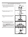
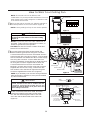
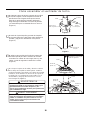
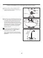
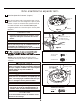
How to Assemble Your Ceiling Fan
1. Remove the hanger ball portion from the downrod/
hanger ball assembly by loosening the set screw in the
hanger ball until the ball falls freely down the downrod.
Remove the pin from the downrod, then remove the
hanger ball. Retain the pin and hanger ball for reinstal-
lation in Step 6. (Figure 1)
Downrod
Set Screw
Pin
Hanger Ball
Figure 1
Figure 2
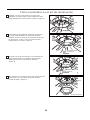
3. Loosen the two set screws and nuts in the downrod
support of the motor assembly. Route the black, white,
blue wires and safety cable through the downrod.
(Figure 3)
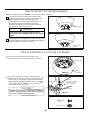
4. Slide downrod into the downrod support on top of
the motor. Install the clevis pin by aligning the holes
in the downrod support with holes in the downrod.
Secure clevis pin with hairpin clip. Tighten the two set
screws with nuts in the downrod support. (Figure 4)
WARNING
It is critical that the clevis pin in the downrod support
is properly installed and the set screws and nuts are
securely tightened. Failure to do so could result in
the fan falling.
2. Remove the hairpin clip and clevis pin from the
bottom of the downrod. Retain the pin and clip for
reinstallation in Step 4. (Figure 2)
Hairpin
Clip
Clevis Pin
Clevis Pin
Figure 4
Figure 5
5. Route wires and safety cable through motor coupling
cover, canopy screw cover and ceiling canopy. (Figure 5)
Motor Coupling
Cover
Ceiling Canopy
Canopy Screw
Cover
Downrod
Hairpin Clip
Set Screws and
Locking Nuts (2)
Downrod
Set Screws
and Nuts (2)
Black, White, Blue wires
and Safety Cable
Figure 3

7
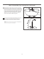
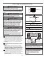
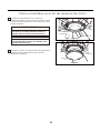
How to Assemble Your Ceiling Fan (continued)
NOTE:
All set screws must be checked, and retightened
where necessary, before installation.
Figure 6
Figure 7
7. Cut off excess lead wire approximately 6 to 9 inches
above the top of the downrod. Strip insulation off
1/2 inch from the end of each lead wire. (Figure 7)
6. Reinstall the hanger ball on the downrod as follows.
Route the black, white and blue wires and safety cable
through the hanger ball. Position the pin through the two
holes in the downrod and align the hanger ball so the pin
is captured in the groove in the top of the hanger ball.
Pull the hanger ball up tight against the pin. Securely
tighten the set screw in the hanger ball. A loose set
screw could create fan wobble. (Figure 6)

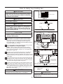
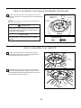
1. Using the
3
»8Ý x 2Ý lag bolt and flat washer, attach
safety cable to ceiling joist or wood structural member.
The lag bolt will pass through the flat washer, safety
cable loop, and into the building structure (Figure 3).
<RXZLOOILUVWGULOODóÝSLORWKROHLQWRWKHEXLOGLQJVWUXcture
to prevent splitting or cracking.
2. Securely attach the hanger bracket to ceiling junction
box acceptable for ceiling fan support..
NOTE: Ceiling support cable cannot be secured to
junction box only, it must be directly secured to ceiling
joist or structural member using the ǪÝ x 2Ý lag bolt and
À at washer. (Figure 3)
3. Make sure the electrical supply wires, including the
hanger bracket grounding wire and safety cable are
pulled through the downrod, between the hanger bracket
and the junction box so that electrical connections can be
made later.
Carefully lift the fan and seat the downrod/hanger ball
assembly on the hanger bracket that was just attached to
the ceiling joist. Be sure the groove in the ball is lined up
with tab on the hanger bracket. (Figure 4)
5. Attach the safety cable to ceiling support cable. Slide
cable clamp onto safety cable (from fan). Place the end
of cable through the loop of ceiling support cable. Pull as
much cable through loop as possible. Feed end of cable
into clamp hole and firmly tighten screw (Figure 4). Cut
off excess safety cable.
ÝÝ r
r.
r
ÝÝ
À r.
r.
of
4.
WARNING
The fan must be hung with at least 7´ of clearance from
floor to blades. (Figure 2)
WARNING
The outlet box must be securely anchored and capable
of withstanding a load of at least 35 lbs. Hanger bracket
must seat
rmly against outlet box. If the outlet box is
recessed, remove wallboard until bracket contacts box.
If bracket and/or outlet box are not securely attached,
the fan could wobble or fall.
CAUTION
Do not connect fan blades until the fan is completely
installed. Hanging fan with blades connected may result
in damage to the fan blades.
WARNING
To avoid possible electrical shock, be sure electricity is
turned off at the main fuse box before hanging. (Figure 1)
NOTE: If you are not sure if the outlet box is grounded,
contact a licensed electrician for advice, as it must be
grounded for safe operation.
WARNING
Failure to seat tab in groove could cause damage to
electrical wires and possible shock or fire hazard.
How to Hang Your Ceiling Fan
Figure 2
%'+.+0)
(.114
01.'55
6*#0
(''6
Figure 1
/#+0(75'$1:
911&/'/$'4
r:r#2241:
%'+.+0),1+56
%'+.+0)
,70%6+10
$1:
*#0)'4$4#%-'6
%'+.+0)
5722146
%#$.'
Figure 3
:
HARDWARE USED:
Figure 4
6#$
016'5722.;9+4'5#0&(#0
9+4'51/+66'&(14%.#4+6;
&19041&*#0)'4
$#..#55'/$.;
#66#%*5#('6;
%#$.'61%'+.+0)
5722146%#$.'
%'+.+0)5722146
%#$.'%.#/2
95%4'9
To avoid possible shock, do not pinch wires
between the downrod/hanger ball assembly and the
hanger bracket.
WARNING
8

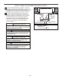
How to Wire Your Ceiling Fan
MAIN FUSE BOX
Figure 2
Figure 1
Figure 4
Green Wire
from Supply
(Ground)
White Wire
from Supply
White Wire
from Receiver
Green Wire
from Hanger
Bracket (Ground)
Green Wire
from Hanger
Ball (Ground)
Listed
Outlet Box
Household
Supply
Black Wire
from Supply
Black Wire
from Receiver
Receiver
Figure 3
x 6WIRE
CONNECTORS
HARDWARE USED:
Bl
ue to
Li
g
ht
Bl
ac
k t
o
M
o
t
or
W
hit
e
t
o
M
o
t
or
all
To avoid possible electrical shock, be sure electricity
is turned off at the main fuse box before wiring
(Figure 2).
WARNING
NOTE:
If you are not sure if the outlet box is
grounded, contact a licensed electrician for advice, as
it must be grounded for safe operation.
NOTE:
If you feel that you do not have enough electrical
wiring knowledge or experience, have your fan installed
by a licensed electrician.
Check to see that all connections are tight, including
ground, and that no bare wire is visible at the wire
connectors except for the ground wire. Do not
operate fan until the blades are in place. Noise and
motor damage could result.
WARNING
3. After connections have been made, turn leads
upward and carefully push leads into the outlet
box, with the white and green leads to one side
of the box and the black leads to the other side.
(Figure 4)
CAUTION: INCORRECT WIRE CONNECTION WILL
DAMAGE THIS RECEIVER.
2. Connect green wires from hanger bracket and
downrod to bare (ground) wire using wire connector.
Connect black wire from receiver unit marked “AC IN L”
to black supply wire using wire connector. Connect white
wire from receiver unit marked “AC IN N” to white supply
wire using wire connector. Connect white wire from
receiver unit marked “TO MOTOR N” to white wire from
fan using wire connector supplied with receiver unit.
Connect black wire from receiver unit marked “TO
MOTOR L” to black wire from fan using wire connector
supplied with receiver unit. Lastly, connect blue wire
from receiver unit to the blue fan light wire using wire
connector supplied with receiver unit. (Figure 3)
1. To set the code on receiver unit, slide dip switches to
the same positions as set on the remote. (Figure 1)
NOTE: The remote unit has 32 different code
combinations. To prevent possible interference from or to
other remote units, simply change the combination code
in the remote and receiver.
NOTE: Factory setting is all up. Do not use this position.
9
Dip Switch
ON DIP
1 2 3 4 5
Receiver Unit

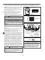
How to Assemble Your Ceiling Fan Blades
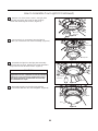
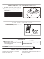
How to Install Your Canopy Housing
2. Securely attach and tighten the canopy screw cover
over the shoulder screws in the hanger bracket utilizing
the keyslot twist-lock feature. (Figure 2)
1. Remove one of the two shoulder screws in the
hanger bracket. Loosen the second shoulder screw
without fully removing it. Assemble canopy by
rotating key slot in canopy over shoulder screw in
hanger bracket. Tighten shoulder screw. Fully
assemble and tighten second shoulder screw that
was previously removed. (Figure 1)
WARNING
To avoid possible fire or shock, make sure that the
electrical wires are completely inside the canopy
housing and not pinched between the housing and the
ceiling.
NOTE: This step is applicable after the neccessary wiring is completed.
Ceiling Canopy
10
HARDWARE USED:
x 15
x 15
FIBER WASHERS
WASHER HEAD
SCREWS
3/16ß-24
2.
Position the blade over the blade holder with
threaded posts showing. Make sure the bottom edge
of the blade is fully seated against the blade holder.
:LWKDSKLOOLSVVFUHZGULYHUWLJKWHQÝZDVKHU
head screws and fiber washers to secure the blade
to the blade holder. (Figure 2)
Do not connect fan blades until the fan is completely
install
ed. Installing the fan with blades assembled
may result in damage to the fan blades.
CAUTION
1. Remove and discard the five rubber motor
stops/screws from the motor assembly. (Figure 1)
Figure 1
Blade
Blade Holder
Figure 2
Ý
Washer Head Screws
and Fiber Washers
(3 each per blade)
Figure 1
Canopy Screw
Cover
Figure 2
Motor Stops
Motor
Assembly

How to Assemble Your Light Kit
How to Assemble Your Ceiling Fan Blades (Continued)
11
NOTE: Periodically check blade holder hardware and
resecure if necessary.
3. Secure the blade holders to the bottom of the motor
DVVHPEO\XVLQJWKHÝVFUHZVIURPWKHKDUGZDUHEDJ
(Figure 3)
To reduce the risk of personal injury, do not bend the
blade holders when installing, balancing the blades
or cleaning the fan. Do not insert foreign objects in
between the rotating blades.
WARNING
!
To reduce the risk of electric shock, disconnect the
electrical supply circult to the fan before installing
light kit.
CAUTION
Blade Holder
SHUDVVHPEO\
HARDWARE USED:
x 10
SCREWS
Figure 3
6FUHZV
Figure 1
Figure 2
1. 5HPRYHRQHRIWKHWKUHHVFUHZVLQWKHVXSSRUW
EUDFNHWDQGUHWDLQWKHVFUHZIRUODWHU6OLJKWO\ORRVHQ
WKHUHPDLQLQJWZRVFUHZV(Figure 1)
Motor
Assembly
Motor
Assembly
Light Plate
Assembly
2.$VVHPEOHWKHOLJKWSODWHDVVHPEO\WRWKHDGDSWRU
SODWHRIWKHPRWRUDVVHPEO\XVLQJWKHWZRNH\VORWVLQ
WKHOLJKWSODWHDVVHPEO\5HSODFHWKHWKLUGVFUHZDQG
VHFXUHDOOWKUHHVFUHZV)LJXUH

How to Assemble Your Light Kit Continued)
12
Light Plate
Assembly
Light Plate
Assembly
Figure 3
3. Remove one of the three screws in the light plate
assembly and retain the screw for later. Slightly
loosen the remaining two screws. (Figure 3)
4. Connect the 2 pin connectors from the light kit
to the 2 pin connectors from motor assembly. (Figure 4)
5. Assemble the light kit to the light plate assembly
using the two key slots. Replace the screw removed in
Step 3 and secure all three screws. (Figure 5)
Light Kit
Light Kit
Light Kit
Motor
Assembly
Figure 4
Figure 5
Figure 6
Glass
The light source is designed for this specific
application and can overheat if serviced by untrained
personnel. If any servicing is required, the product
should be returned to an authorized service facility
for examination or repair.
CAUTION
6. Assemble the glass to the light kit by twisting
in a clockwise direction. Do not overtighten. (Figure 6)

How to Operate Your Ceiling Fan
13
Figure 1
Figure 2
Figure 4
MAIN FUSE BOX
For illustrative purposes only-not
intended to cover all types of controls
2. Restore electrical power to the outlet box by turning
the electricity on at the main fuse box. (Figure 2)
Check to see that all connections are tight, including
ground, and that no bare wire is visible at the wire
connectors, except for the ground wire. Do not
operate fan until the blades are in place. Noise and
fan damage could result.
WARNING
1. IMPORTANT: Using a full range dimmer switch
(not included) to control fan speed will damage the fan.
To reduce the risk of fire or electrical shock, do not use
a full range dimmer switch to control the fan speed.
(Figure 1)
WARNING
Do not operate this fan with a variable (Rheostat) wall
controller or dimmer switch. Doing so could result in
damage to the ceiling fan's remote control unit.
3. To make fan operational, install 23A/12V battery
(included) in hand-held remote transmitter, with fan
power off. Then follow the remote code setting
process. (If not used for long periods of time, remove
battery toprevent damage to transmitter). Store the
remote away from excessive heat or humidly.
(Figure 3)
NOTE: The remote unit has 32 different code
combinations. To prevent possible interference from or
to other remote units, simply change the combination
code in the remote and receiver.
4. To set the remote code with a small screwdriver or
ball point pen (neither included), slide dip switches
firmly up or down. (Figure 4)
NOTE: Factory setting is all up. Do not use this
position.
Dip Switch
ON DIP
1 2 3 4 5
Remote
12V 23A
Battery (1 pcs)
Figure 3
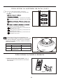
5. Remote functions: (Figure 5)
,QGLFDWRU/('OLJKWIDQVSHHG
EXWWRQ7XUQVIDQRII
)DQ6SHHG
Turns fan on and turns speed up.
Turns fan on and turns speed down.
/LJKWEXWWRQ7XUQVOLJKWRQDQGRII
Increases light output level.
Decreases light output level.
Tap and the fan and light will turn off after
3 hours.
Tap and the fan and light will turn off after
6 hours.
Tap and the fan and light will turn off after
1 hour.
Figure 5

How to Install Your Remote Control
Figure 1
1. Installing Wall Holder: (Figure 1)
Attach wall holder using the two provided screws.
How to Operate Your Ceiling Fan (continued)
14
Maintenance
How to Clean Your Ceiling Fan Blades
1. ylnoehtsinafgniliecwenruoyfogninaelccidoireP
maintenance that is needed.
When cleaning, use only a soft brush or lint free cloth
.hsinif ehtgnihctarcsdiovaot
Abrasive cleaning agents are not required and should
be avoided to prevent damage to finish.
Periodic light dusting of the blades is recommended.
A feather duster will work best.
Avoid using water, cleansers, or harsh rags, which can
warp and ruin the blades.
CAUTION
Do not use solvents when cleaning your ceiling fan. It
could damage the motor or the blades and create the
possibility of electrical shock.
RECOMENDED: Periodically check that the blade holders to motor hub screws are secure and tight.
Season
Summer
Winter
Rotation Direction Switch Position
Clockwise
Counterclockwise
Reverse Switch Information
Right
Left
6. If airflow is desired in the opposite direction, turn
the fan off and wait for the blades to stop turning.
Then slide the reverse switch on top of motor
assembly to the opposite position and turn fan on
again. (Figure 6 )
Reversing
Switch
Figure 6

15
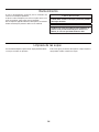
HOW TO ORDER REPAIR PARTS
When ordering repair parts, always give the following information:
Part Number
Part Description
Fan Model Number
Contact your retail store for repair parts.
Before discarding packaging material, be certain all parts have been removed.
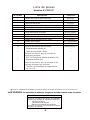
** Insert FINISH CODES (Refer to fan model number located on downrod support)
Parts List
Model No. FP8533**
Reference # Part #
ADR1-45**
PG155**
AP1115**
Motor Coupling Cover
APPAC2604**
AMA8533**
Blade Holder Set
Motor Assembly
AP853305**Blade Set
AP853303BL
AP255BL
AP260**
Light Plate Assembly
HDWFP8533**
1
2
3
4
5
6
7
8
9
AP853304Light Kit/Glass Assembly
10
11
12
RCCA05005001
TR500
Receiver Unit
Hand-Held Remote
13
—
—
—
—
—
—
——
—
—
Hanger Bracket Assembly
Hanger Ball/Downrod Assembly
Ceiling Canopy
Canopy Screw Cover Assembly
Wire Connectors (4)
Bag Assembly Safety Cable
Loose Hardware Bag:
Blade Mounting Hardware Bag:
:DVKHU+HDG6FUHZVÝ
Fiber Washer (16)
Blade Holder Mounting Hardware Bag:
3DQ+HDG6FUHZÝZLWK/RFN:DVKHU
Description

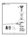
16
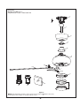
Model FP8533**
Exploded-View Illustration
NOTE: The illustration shown is not to scale or its actual con guration may vary.
Product/parts are subject to change without notice.
Figure 1
DOREN
™
13
1
2
3
4
5
6
7
13
13
9
10
8
13
1112

4. Replace with fresh battery.
4. Dead battery in remote control.
17
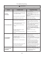
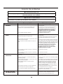
Troubleshooting
For your own safety turn off power at fuse box or circuit breaker before trouble shooting your fan.
WARNING
Trouble Probable Cause Suggested Remedy
1.FAN WILL
NOT START
1. Check main and branch circuit fuses
or circuit breakers.
2. Check line wire connections to fan
and switch wire connections in the
switch housings.
CAUTION: Make sure main power is
turned off !
1. Fuse or circuit breaker blown.
2. Loose power line connections to the
fan, or loose switch wire connections
in the switch housing.
2.FAN SOUNDS NOISY
1. Attach blades to fan before operating.
2. Check to make sure all screws in
motor housing are snug (not over-
tight).
3. Check to make sure the screws which
attach the fan blade holders to the
motor flywheel are tight.
4. Check to make sure wire connectors
in switch housing are not rattling
against each other or against the
interior wall of the switch housing.
CAUTION: Make sure main power is
turned off !
5. Tighten screws securely.
1. Blades not attached to fan.
2. Loose screws in motor housing.
3. Screws securing fan blade holders to
motor flywheel are loose.
4. Wire connectors inside housing
rattling.
5. Screws holding blades to blade
holders are loose.
3.FAN WOBBLES
EXCESSIVELY
1. Tighten both setscrews securely in
downrod support.
2. Tighten the setscrew in the downrod/
hanger ball assembly.
3. Check to be sure screws which attach
the fan blade holders to the flywheel
are tight.
4. Check to be sure the fan blade
holders seat firmly and uniformly to
the surface of the motor housing.
If holders are seated incorrectly,
loosen the screws and retighten.
5. Tighten the hanger bracket screws to
the outlet box, and secure outlet box.
6. Balance blades using balance kit
provided in hardware bag.
1. Setscrew in downrod support is loose.
2. Setscrew in downrod/hanger ball
assembly is loose.
3. Screws securing fan blade holders to
flywheel are loose.
4. Blade holders not seated properly.
5. Hanger bracket and/or ceiling outlet
box is not securely fastened.
6. Fan blades out of balance.
4.NOT ENOUGH AIR
MOVEMENT
1. If possible, consider using a longer
downrod (not included, you can buy
the longer downrod from
fanimation.com).
6. Lower housing support set screw
loose.
6. Tighten set screw securely.
3. Make sure reversing switch position is
all the way to one side.
3. Reversing switch in neutral position.

Copyright 2019 Fanimation
2019/01 V.01
10983 Bennett Parkway
Zionsville, IN 46077
Phone: 888-567-2055
Outside U.S.: 317-733-4113
FANIMATION.COM
FAX: 866-482-5215

MODELO #FP8533**
™
VENTILADOR DE TECHO DOREN
ADJUNTE SU RECIBO AQUÍ Y REGISTRE SU VENTILADOR EN FANIMATION.COM
LEA Y GUARDE ESTAS INSTRUCCIONES
Peso neto 8.4 kg (18.52 lbs)
Preguntas, problemas, piezas faltantes? Antes de volver a la tienda, llame a nuestro
Departamento de Servicio al Cliente al 1-888-567-2055, 8 a.m. - 5 pm, hora del Este, de
lunes - viernes.
Número de serie
Fecha de compra

GARANTÍA LIMITADA DE POR VIDA DEL MOTOR - Si se produjera una falla en alguna de las partes del motor de su ventilador debido 1.
a un defecto en los materiales o en la fabricación durante el tiempo de vida del comprador original, Fanimation proporcionará la pieza de
repuesto sin cargo una vez que el ventilador defectuoso sea devuelto a nuestro centro de servicios nacional. Se requiere comprobante de
venta. El cliente se hará responsable de todos los gastos de remoción o reinstalación y envío del producto para reparaciones o sustitución.
GARANTÍA DE MANO DE OBRA DEL MOTOR POR UN AÑO - Si el motor de su ventilador fallara antes de cumplirse un año a partir del2.
momento de su compra original debido a defectos en los materiales o en la fabricación, se le efectuará la reparación del mismo sin cargo
en nuestro centro de servicios nacional. El comprador se hará responsable de los gastos de mano de obra luego del período de un año.
El cliente se hará responsable de todos los gastos de remoción o reinstalación y envío del producto parareparaciones o sustitución.
Si otra pieza del ventilador fallara dentro del período de un año a partir de la fecha de compra original debido a un defecto en los 3.
materiales o en la fabricación, repararemos o sustituiremos, según creamos conveniente, la pieza defectuosa sin cargo alguno en
nuestro centro de servicios nacional.
Debido a las diversas condiciones climáticas, esta garantía no cubre cambios en la terminación, incluidos oxidación, corrosión, 4.
falta de brillo o peladuras.
Esta garantía es nula y no se aplica a daños por instalación incorrecta, negligencia, accidentes, uso indebido, exposición al calor o 5.
a la humedad en exceso, o como resultado de cualquier modificación realizada al producto original.
Todos los gastos de remoción y reinstalación del ventilador son responsabilidad exclusiva del propietario, y no de la tienda que 6.
vendió el ventilador ni de Fanimation.
Fanimation se reserva el derecho de modificar o discontinuar un producto en cualquier momento, o sustituir cualquier pieza según 7.
lo establecido por esta garantía.
En ningún caso se podrá devolver un ventilador sin previa autorización por parte de Fanimation. Las devoluciones autorizadas 8.
deberán ir acompañadas del recibo de venta y deberán enviarse a Fanimation, previo pago del flete. El ventilador que se devuelva
deberá estar embalado en forma adecuada a fin de evitar daños durante el transporte. Fanimation no se hará responsable de los
daños que resulten del embalaje incorrecto del producto.
Se entiende que las reparaciones y las sustituciones son el único recurso disponible de Fanimation. No existe ninguna otra 9.
garantía expresa o implícita. Por la presente, Fanimation niega todas las garantías implícitas, que incluyen, entre otras, la
comerciabilidad y la aptitud para determinado fin hasta donde la ley lo permita. Algunos estados no permiten limitaciones sobre las
garantías implícitas. Fanimation no se hará responsable por daños accidentales, resultantes o especiales derivados del uso o el
rendimiento del producto o en conjunción con éste, excepto en los casos en los que la ley así lo disponga. Esta garantía le otorga
derechos legales especiales y es posible que también goce de otros derechos que pueden variar según el estado.
Es normal que se produzca un cierto movimiento oscilante y esto no debe considerarse un problema o defecto.10.
GARANTÍA LIMITADA DE POR VIDA
Se extiende al comprador original de un ventilador Fanimation
Instrucciones de seguridad importantes
ADVERTENCIA: Siga estas instrucciones para prevenir incendios, descargas eléctricas y lesiones personales graves.
Lea el manual del propietario y la información de seguridad antes de instalar su nuevo ventilador. Observe los diagramas de 1.
ensamblaje adjuntos.
Antes de llevar a cabo el mantenimiento o la limpieza de la unidad, desconecte la electricidad en el panel de servicio y bloquee los 2.
medios de desconexión del mismo para evitar que se active accidentalmente. Si no se pueden bloquear los medios de desconexión
del servicio, coloque un dispositivo de advertencia, como una etiqueta, en el panel de servicio.
Tenga cuidado con la estructura y las aspas del ventilador cuando limpie, pinte o trabaje cerca del mismo. Desconecte siempre la 3.
electricidad del ventilador de techo antes de llevar a cabo el mantenimiento.
No coloque nada en las aspas del ventilador cuando éste se encuentra en funcionamiento.4.
No accione el conmutador inversor hasta que las aspas del ventilador se hayan detenido por completo.5.
Instrucciones de seguridad adicionales
Para evitar posibles descargas eléctricas, asegúrese de que la electricidad esté desconectada en la caja de fusibles antes de realizar1.
la instalación eléctrica, y no haga funcionar el ventilador sin las aspas.
Todos los procedimientos de conexión eléctrica e instalación deben cumplir con los Códigos eléctricos nacionales (ANSI/NFPA 2.
70) y Códigos locales. El ventilador de techo debe estar conectado a tierra a fin de prevenir posibles descargas eléctricas. La
instalación eléctrica debe ser llevada a cabo o aprobada por un electricista autorizado.
Se debe fijar bien la base del ventilador; ésta debe ser capaz de soportar sin problemas al menos 15,9 kg (35 lb). Consulte la página3.
24 del manual del propietario para ver los requisitos de soporte. Si tiene dudas, consulte a un electricista calificado.
Las aspas del ventilador deben instalarse por lo menos a 2 m (7 pies) del suelo, a fin de evitar un contacto accidental con las mismas.4.
Siga las recomendaciones sobre el método correcto de instalación eléctrica de su ventilador de techo. Si no posee la experiencia o 5.
los conocimientos eléctricos adecuados, contrate a un electricista autorizado para instalar el ventilador.
Utilícelo solo con los kits de iluminación adecuados para ubicaciones seco.6.
ADVERTENCIA: Este producto está diseñado para ser usado sólo con las piezas suministradas o los accesorios indicados
específicamente para el mismo. Si utiliza piezas o accesorios que no están indicados para su uso con este producto, podría
sufrir lesiones personales o dañar el ventilador.
ADVERTENCIA: Para reducir el riesgo de lesiones personales, no doble los soportes de las aspas (borde o soporte de aspas) al instalar
los soportes, balancear las aspas o limpiar el ventilador. No coloque objetos extraños entre las aspas del ventilador en funcionamiento.
ADVERTENCIA: Para reducir el riesgo de incendios o descargas eléctricas. No use este ventilador con un dispositivo de control de la
velocidad de estado sólido.
ADVERTENCIA: Para reducir el riesgo de descarga eléctrica. Desconecte el circuito de la fuente de alimentación al ventilador antes de
instalar el kit de iluminación.
AVERTISSEMENT: Ce produit est conçu pour utiliser uniquement les pièces l'accompagnant et/ou les accessoires spécifiquement
conçus pour ce produit. L'utilisation de pièces et/ou d'accessoires qui ne sont pas conçus pour être utilisés avec ce produit peut
provoquer des blessures ou des dommages matériels.
AVERTISSEMENT: Afin de réduire le risque de blessure, ne pliez pas le support de pale (bride ou porte-pale) lors de l'installation des
supports, de l'équilibrage des pales ou du nettoyage du ventilateur. N'insérez pas de corps étrangers entre les pales du ventilateur en
rotation.
AVERTISSEMENT: Pour réduire le risque d’incendie ou d’électrocution. N’utilisez pas ce ventilateur avec un dispositif de contrôle de la
vitesse à semi-conducteur.
AVERTISSEMENT: Pour réduire le risque d’électrocution. Débranchez le circuit d’alimentation électrique du ventilateur avant d’installer le kit
d’éclairage.
La page est en cours de chargement...
La page est en cours de chargement...
La page est en cours de chargement...
La page est en cours de chargement...
La page est en cours de chargement...
La page est en cours de chargement...
La page est en cours de chargement...
La page est en cours de chargement...
La page est en cours de chargement...
La page est en cours de chargement...
La page est en cours de chargement...
La page est en cours de chargement...
La page est en cours de chargement...
La page est en cours de chargement...
La page est en cours de chargement...
La page est en cours de chargement...
La page est en cours de chargement...
La page est en cours de chargement...
La page est en cours de chargement...
La page est en cours de chargement...
-
 1
1
-
 2
2
-
 3
3
-
 4
4
-
 5
5
-
 6
6
-
 7
7
-
 8
8
-
 9
9
-
 10
10
-
 11
11
-
 12
12
-
 13
13
-
 14
14
-
 15
15
-
 16
16
-
 17
17
-
 18
18
-
 19
19
-
 20
20
-
 21
21
-
 22
22
-
 23
23
-
 24
24
-
 25
25
-
 26
26
-
 27
27
-
 28
28
-
 29
29
-
 30
30
-
 31
31
-
 32
32
-
 33
33
-
 34
34
-
 35
35
-
 36
36
-
 37
37
-
 38
38
-
 39
39
-
 40
40


Fanimation FP8533PN Le manuel du propriétaire
- Catégorie
- Ventilateurs ménagers
- Taper
- Le manuel du propriétaire
dans d''autres langues
Documents connexes
-
Fanimation LP8577LBN Le manuel du propriétaire
-
-
-
-
-
-
Fanimation FP8003BPN Le manuel du propriétaire
Autres documents
-
NOMA Landon Indoor Le manuel du propriétaire
-
-
Modern Forms FR-W2006-62L-MW Guide d'installation
-
 Kichler Lighting 35063 Manuel utilisateur
-
 Kichler Lighting 300200PN Manuel utilisateur
-
 Kichler Lighting 310204WCP Manuel utilisateur
-
Midmark Preva Intraoral X-ray System Guide d'installation


