Fanimation FP8519BL Le manuel du propriétaire
- Catégorie
- Ventilateurs ménagers
- Taper
- Le manuel du propriétaire
Ce manuel convient également à

ATTACH YOUR RECEIPT HERE AND REGISTER YOUR FAN AT FANIMATION.COM
READ AND SAVE THESE INSTRUCTIONS
Serial Number
Purchase Date
Español p. 19
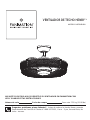
MODEL #FP8519BL
™
CEILING FAN
Questions, problems, missing parts? Before returning to your retailer, call our customer
service department at 1-888-567-2055, 8 a.m.-5 p.m., EST, Monday-Friday.
Net Weight 15.88 lbs (7.2 kgs)
HENRY

Important Safety Instructions
WARNING: To avoid fire, shock and serious personal injury, follow these instructions.
1. Read your owner’s manual and safety information before installing your new fan. Review the accompanying assembly
diagrams.
2. Before servicing or cleaning unit, switch power off at service panel and lock service panel disconnecting means to prevent
power from being switched on accidentally. When the service disconnecting means cannot be locked, securely fasten a
warning device, such as a tag, to the service panel.
3. Be careful of the fan and blades when cleaning, painting, or working near the fan. Always turn off the power to the ceiling
fan before servicing.
4. Do not insert anything into the fan blades while the fan is operating.
Additional Safety Instructions
1. To avoid possible shock, be sure electricity is turned off at the fuse box before wiring, and do not operate fan without
blades.
2. All wiring and installation procedures must satisfy National Electrical Codes (ANSI/ NFPA 70) and Local Codes. The
ceiling fan must be grounded as a precaution against possible electrical shock. Electrical installation should be made or
approved by a licensed electrician.
3. The fan base must be securely mounted and capable of reliably supporting at least 35 lbs. (fan and accessories not to
exceed 35 lbs. or 15.88 kgs.). See page 5 of owner’s manual for support requirements. Consult a qualified electrician if in
doubt.
4. The fan must be mounted with the fan blades at least 7 feet from the floor to prevent accidental contact with the fan blades .
5. Follow the recommended instructions for the proper method of wiring your ceiling fan. If you do not have adequate
electrical knowledge or experience, have your fan installed by licensed electrician.
6. Suitable for use with solid-state speed controls.
WARNING
:
TO REDUCE THE RISK OF ELECTRIC SHOCK, THIS FAN MUST BE INSTALLED WITH A GENERAL USE,
ISOLATING WALL CONTROL/SWITCH.
WARNING
:
This product is designed to use only those parts supplied with this product and/or accessories designated
specifically for use with this product. Using parts and/or accessories not designated for use with this product could result in
personal injury or property damage.
WARNING
:
To reduce the risk of personal injury, do not bend the blade bracket (flange or blade holder) when installing the
WARNING
:
Mount to an outlet box marked acceptable for fan support.
brackets, balancing the blades, or cleaning the fan. Do not insert foreign objects in between rotating fan blades.
LIMITED LIFETIME WARRANTY
Extends to the original purchaser of a Fanimation Fan
1. LIMITED LIFETIME MOTOR WARRANTY - If any part of your fan motor fails, due to a defect in materials or workmanship
during the lifetime of the original purchaser, Fanimation will provide the replacement part free of charge, when the defective
fan is returned to our national service center. Proof of purchase is required. Customer shall be responsible for all costs
incurred in the removal or reinstallation and shipping of the product for repairs or replacement.
2. ONE YEAR MOTOR LABOR WARRANTY - If your fan motor fails at any time within one year from the original purchase, due
to defects in materials or workmanship, labor to repair the motor will be provided free of charge at our national service
center. Purchaser will be responsible for labor charges after this one-year period. Customer shall be responsible for all
costs incurred in the removal or reinstallation and shipping of the product for repairs or replacement.
3. If any other part of your fan fails at any time within one year after original purchase, due to a defect in materials or
workmanship, we will repair, or replace, at our option, the defective part free of charge for parts and labor performed at our
national service center.
4. Because of varying climate conditions, this warranty does not cover changes in the finish, including rusting, pitting,
corroding, tarnishing, or peeling.
5. This warranty is void and does not apply to damage from improper installation, neglect, accident, misuse, exposure to
extremes of heat or humidity, or as a result of any modification to the original product.
6. All costs of removal and reinstallation of the fan are the sole responsibility of the owner of the fan and not the store that
sold the fan or Fanimation.
7. Fanimation reserves the right to modify or discontinue any product at any time and may substitute any part under this
warranty.
This device complies with Part 15 of the FCC Rules. Operation is subject to the following two conditions:
(1) This device may not cause harmful interference, and (2) this device must accept any interference received, including
interference that may cause undesired operation. Please note that changes or modifications not expressly approved by the
party responsible for compliance could void the user's authority to operate the equipment.
Note: This equipment has been tested and found to comply with the limits for Class B digital device, pursuant to part 15 of the
FCC Rules. These limits are designed to provide reasonable protection against harmful interference in a residential installation.
This equipment generates, uses and can radiate radio frequency energy and, if not installed and used in accordance with the
instructions, may cause harmful interference to radio or television reception, which can be determined by turning the
equipment off and on, the user is encouraged to try to correct the interference by one or more of the following measures:
- Reorient or relocate the receiving antenna.
- Increase the separation between the equipment and the receiver.
- Connect the equipment into an outlet on a circuit different from that to which the receiver is connected.
Consult the dealer or an experienced radio/TV technician for help.
5. The appliance is not intended for use by young children or infirm persons without supervision. Young children should be
supervised to ensure that they do not play with the appliance.
8. For supply connections, if the conductor of a fan is identified as a grounded conductor, then it should be connected to a
grounded conductor power supply. If the conductor of a fan is identified as an ungrounded conductor, then it should be
connected to an ungrounded conductor power supply. If the conductor of a fan is identified for equipment grounding, then it
should be connected to an equipment-grounding conductor.
WARNING: Do not operate this fan with a variable (Rheostat) wall controller or dimmer switch. Doing so could result in damage
to the ceiling fan's remote control unit.
7. This fan is to be used in dry and damp locations.

LIMITED LIFETIME WARRANTY
Extends to the original purchaser of a Fanimation Fan
9. It is understood that any repair or replacement is the exclusive remedy available from Fanimation. There is no other
expressed or implied warranty. Fanimation hereby disclaims any and all implied warranties, including, but not limited to
those of merchantability and fitness for a particular purpose to the extent permitted by law. Some states do not allow
limitations on implied warranties. Fanimation will not be liable for incidental, consequential, or special damages arising out
of or in conjunction with product use or performance, except as may otherwise be accorded by law. This warranty gives you
special legal rights and you may also have other rights that vary from state to state.
10.A certain amount of wobble is normal and should not be considered a problem or a defect.
Unpacking Instructions . . . . . . . . . . . . . . . . . . . . . . . . . . . . . . .4
Energy Efficient Use of Ceiling Fans . . . . . . . . . . . . . . . . . . . . .5
Electrical and Structural Requirements . . . . . . . . . . . . . . . . . .5
How to Assemble Your Ceiling Fan . . . . . . . . . . . . . . . . . . . . . .7
How to Hang Your Ceiling Fan . . . . . . . . . . . . . . . . . . . . . . . . . .9
How to Wire Your Ceiling Fan . . . . . . . . . . . . . . . . . . . . . . . . . 10
How to Install Your Canopy Housing . . . . . . . . . . . . . . . . . . . 11
Table of Contents
8. Under no circumstances may a fan be returned without prior authorization from Fanimation. The receipt of purchase must
accompany authorized returns and must be sent freight prepaid to Fanimation. The fan to be returned must be properly
packed to avoid damage in transit; Fanimation will not be responsible for any damage resulting from improper packaging.
How to Operate Your Ceiling Fan . . . . . . . . . . . . . . . . . . . . . .13
How to Assemble Your Light Kit and Glass. . . . . . . . . . . . . . .11
Maintenance . . . . . . . . . . . . . . . . . . . . . . . . . . . . . . . . . . . . . . . .14
Troubleshooting . . . . . . . . . . . . . . . . . . . . . . . . . . . . . . . . . . . . .15
Parts List . . . . . . . . . . . . . . . . . . . . . . . . . . . . . . . . . . . . . . . . . .16
Exploded-View Illustration . . . . . . . . . . . . . . . . . . . . . . . . . . . .17
How to Install Your Remote Control. . . . . . . . . . . . . . . . . . . . .14

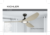
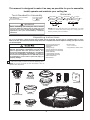
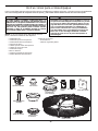
1. Check to see that you have received the following parts:
NOTE:
If you are uncertain of part description, refer to
exploded view illustration.
4
Unpacking Instructions
For your convenience, check-off boxes are provided next to each step. As each step is completed, place a check
mark in the box. This will insure that all steps have been completed and will be helpful in finding your place should
you be interrupted.
Do not install or use fan if any part is damaged or
missing. This product is designed to use only those
parts supplied with this product and/or any
accessories designated specifically for use with this
product by Fanimation. Substitution of parts or
accessories not designated for use with this product
by Fanimation could result in personal injury or
property damage.
Hanger Bracket
Assembly
Downrod/
Hanger Ball Assembly
Motor Assembly
Hardware Bags
This manual is designed to make it as easy as possible for you to assemble,
install, operate and maintain your ceiling fan
Tools Needed for Assembly
ne hillips head screwdriver
One stepladder
nstalled ire ength
ire i e
Before assembling your ceiling fan, refer to section
on proper method of wiring your fan (page 10). If you
feel you do not have enough wiring knowledge or
experience, have your fan installed by a licensed
electrician.
WARNING
!
One wire stripper
p to ft
ft
One lade
screwdriver
Materials
iring outlet o and o connectors ust e of type
re
uired y the local code he ini u wire would e a
conductor wire with ground of the following si e:
NOTE:
Place the parts from the loose parts bags in a small
container to keep them from being lost. If any parts are
missing contact your local retailer.
Canopy Screw
Cover Assembly
Ceiling Cnopy
Motor Coupling
Cover Assembly
Hand-held
Remote
Receiver
Unit
Light Kit/Glass
Assembly
+DQJHU%UDFNHW$VVHPEO\
'RZQURG+DQJHU%DOO
$VVHPEO\
&HLOLQJ&DQRS\
&DQRS\6FUHZ&RYHU$VVHPEO\
0RWRU&RXSOLQJ&RYHU$VVHPEO\
/LJKW.LW*ODVV$VVHPEO\
/LJKW3ODWH/('$VVHPEO\
+DQG+HOG5HPRWH
5HFHLYHU8QLW
0RWRU$VVHPEO\
+DUGZDUHEDJV
– Wire Connectors
±%DJ$VVHPEO\6DIHW\&DEOH
Four wire connectors
Light Plate/LED
Assembly

Energy Efficient Use of Ceiling Fans
Ceiling fan performance and energy savings rely
heavily on the proper installation and use of the ceiling
fan. Here are a few tips to ensure efficient product
performance.
Turn Off When Not in the Room
Ceiling fans cool people, not rooms. If the room is
unoccupied, turn off the ceiling fan to save energy.
Using the Ceiling Fan Year Round
Summer Season: Use the ceiling fan in the counter-
clockwise direction. The airflow produced by the ceiling
fan creates a wind-chill effect, making you “feel” cooler.
Select a fan speed that provides a comfortable breeze,
lower speeds consume less energy.
WinterSeason: Reversethemotor andoperatetheceiling
fan at low speed in the clockwise direction. This produces
a gentle updraft, which forces warm air near the ceiling
down into the occupied space.Remember to adjust your
thermostat when using your ceiling fan - additional energy
and dollar savings could be realized with this simple step!
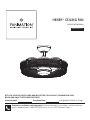
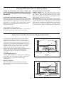
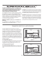
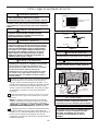
Electrical and Structural Requirements
Your new ceiling fan will require a grounded electrical
supply line of 120 volts AC, 60 HZ, 15 Amp Circuit.
Electrical code requires use of a fan-rated outlet box to
support the extra weight and motion associated with a
ceiling fan. A fan-rated box will be labeled as such and
typically supports up to a 70lb ceiling fan. Fan-Rated
Outlet Boxes vary in ratings and design. Ensure the
ratings of your ceiling fan outlet box meet the
requirements for the ceiling fan being installed. Figure 1,
Figure 2 and Figure 3 depicts different structural
configurations that may be used for mounting the
outlet box.
Low profile box (Figure 1)
$»LQGHHSSDQFDNHER[LVPHDQWWREHVFUHZHGWRD
joist or block. It’s used if only one cable is coming into
the box. It is also available in a saddle-mount
configuration.
CEILING
2" x 4"
CEILING JOIST
OUTLET BOX
Figure 1
Figure 2
2" x 4"
CEILING JOIST
CEILING
OUTLET BOX
Deep box (Figure 2)
$»LQGHHSER[FDQEHDWWDFKHGWREORFNLQJ
between joists and is roomy enough to handle more
than one cable.
5
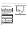
Choosing the Appropriate Mounting Location
Ceiling fans should be installed, or mounted, in the middle
of the room and at least 7 feet from floor to the blade and
18 inches from wall to the blade. If ceiling height allows,
install the fan 8 - 9 feet from floor to the blade for optimal
airflow. Consult your Fanimation Retailer for optional
mounting accessories.

6
Electrical and Structural Requirements (Continued)
If your fan is to replace an existing light fixture, turn
electricity off at the main fuse box at this time and
remove the existing light fixture.
Turning off wall switch is not sufficient. To avoid
possible electrical shock, be sure electricity is
turned off at the main fuse box before wiring. All
wiring must be in accordance with National and
Local codes and the ceiling fan must be properly
grounded as a precaution against possible electrical
shock.
WARNING
WARNING
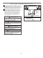
Deep box with brace (Figure 3)
Paired with a deep box, this hanger is meant to span
between two joists and takes the place of wooden
blocking.
To avoid fire or shock, follow all wiring instructions
carefully. Any electrical work not described in these
instructionsshouldbedoneorapprovedby a
licensed electrician.
WARNING
Figure 3
CEILING JOIST
CEILING
OUTLET BOX
To reduce the risk of fire, electric shock, or personal
injury, mount to outlet box marked acceptable for fan
support of 15.9 kg (35 lbs) or less and use mounting
screws provided with the outlet box. Most outlet boxes
commonly used for the support of luminaires are not
acceptable for fan support and may need to be
replaced, consult a qualified electrician if in doubt.
Do not operate this fan with a variable (Rheostat) wall
controller or dimmer switch. Doing so could result in
damage to the ceiling fan's remote control unit.
WARNING

7
Figure 1
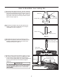
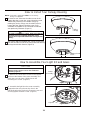
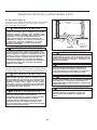
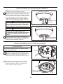
How to Assemble Your Ceiling Fan
Downrod
Set Screw
Pin
Hanger Ball
1. Remove the hanger ball portion from the downrod/
hanger ball assembly by loosening the set screw in the
hanger ball until the ball falls freely down the downrod.
Remove the pin from the downrod, then remove the
hanger ball. Retain the pin and hanger ball for reinstal-
lation in Step 6. (Figure 1)
2.
Remove the hairpin clip and clevis pin from the
bottom of the downrod. Retain the pin and clip for
reinstallation in Step 4. (Figure 2)
Figure 2
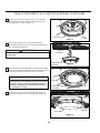
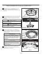
4. Slide downrod into the downrod support on top of
the motor. Install the clevis pin by aligning the holes
in the downrod support with holes in the downrod.
Secure clevis pin with hairpin clip. Install and tighten the
two set screws with nuts in the downrod support.
(Figure 4)
WARNING
It is critical that the clevis pin in the downrod support
is properly installed and the set screws and nuts are
securely tightened. Failure to do so could result in
the fan falling.
Figure 4
Downrod
Set Screws and
Locking Nuts (2)
Hairpin Clip
Figure 3
Black, White, Blue
wires and Safety Cable
3. Loosen the two set screws and locking nuts in
the downrod support of the motor assembly. Route
the black, white and blue wires and safety cable
through the downrod. (Figure 3)
Set Screws
and nuts (2)
Hairpin Clip
Clevis Pin
Clevis Pin

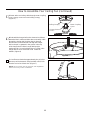
Motor Coupling
Cover
Ceiling Canopy
Canopy Screw
Cover
5. Route wires and safety cable through motor coupling
cover, canopy screw cover and ceiling canopy.
(Figure 5)
6. Reinstall the hanger ball on the downrod as follows.
Route the black, white and blue wires and safety cable
through the hanger ball. Position the pin through
the two holes in the downrod and align the hanger
ball so the pin is captured in the groove in the top
of the hanger ball. Pull the hanger ball up tight
against the pin. Securely tighten the set screw in the
hanger ball. A loose set screw could create fan
wobble. (Figure 6)
8
How to Assemble Your Ceiling Fan (continued)
7. Cut off excess lead wire approximately 6 to 9 inches
above top of the downrod. Strip insulation off 1/2 inch
from the end of each lead wire. (Figure 7)
NOTE:
All set screws must be checked, and retightened
where necessary, before installation.
Figure 6
Figure 7
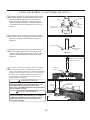
Figure 5

1. Using the
3
»8Ý x 2Ý lag bolt and flat washer, attach
safety cable to ceiling joist or wood structural member.
The lag bolt will pass through the flat washer, safety
cable loop, and into the building structure (Figure 3).
<RXZLOOILUVWGULOODóÝSLORWKROHLQWRWKHEXLOGLQJVWUXcture
to prevent splitting or cracking.
2. Securely attach the hanger bracket to ceiling junction
box acceptable for ceiling fan support.
NOTE: Ceiling support cable cannot be secured to
junction box only, it must be directly secured to ceiling
joist or structural member using the ǪÝ x 2Ý lag bolt and
À at washer. (Figure 3)
3. Make sure the electrical supply wires, including the
hanger bracket grounding wire and safety cable, are
pulled through the downrod, between the hanger bracket
and the junction box so that electrical connections can be
made later.
Carefully lift the fan and seat the downrod/hanger ball
assembly on the hanger bracket that was just attached to
the ceiling joist. Be sure the groove in the ball is lined up
with tab on the hanger bracket. (Figure 4)
5. Attach the safety cable to ceiling support cable. Slide
cable clamp onto safety cable (from fan). Place the end
of cable through the loop of ceiling support cable. Pull as
much cable through loop as possible. Feed end of cable
into clamp hole and firmly tighten screw (Figure 4). Cut
off excess safety cable.
ÝÝ r
r.
r
ÝÝ
À r.
r.
of
4.
WARNING
The fan must be hung with at least 7´ of clearance from
floor to blades. (Figure 2)
WARNING
The outlet box must be securely anchored and capable
of withstanding a load of at least 35 lbs. Hanger bracket
must seat
rmly against outlet box. If the outlet box is
recessed, remove wallboard until bracket contacts box.
If bracket and/or outlet box are not securely attached,
the fan could wobble or fall.
CAUTION
Do not connect fan blades until the fan is completely
installed. Hanging fan with blades connected may result
in damage to the fan blades.
WARNING
To avoid possible electrical shock, be sure electricity is
turned off at the main fuse box before hanging. (Figure 1)
NOTE: If you are not sure if the outlet box is grounded,
contact a licensed electrician for advice, as it must be
grounded for safe operation.
WARNING
Failure to seat tab in groove could cause damage to
electrical wires and possible shock or fire hazard.
Figure 2
%'+.+0)
(.114
01.'55
6*#0
(''6
Figure 1
/#+0(75'$1:
911&/'/$'4
r:r#2241:
%'+.+0),1+56
%'+.+0)
,70%6+10
$1:
*#0)'4$4#%-'6
%'+.+0)
5722146
%#$.'
Figure 3
:
HARDWARE USED:
Figure 4
6#$
016'5722.;9+4'5#0&(#0
9+4'51/+66'&(14%.#4+6;
&19041&*#0)'4
$#..#55'/$.;
#66#%*5#('6;
%#$.'61%'+.+0)
5722146%#$.'
%'+.+0)5722146
%#$.'%.#/2
95%4'9
To avoid possible shock, do not pinch wires
between the downrod/hanger ball assembly and the
hanger bracket.
WARNING
9
How to Hang Your Ceiling Fan

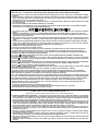
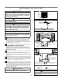
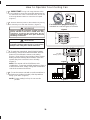
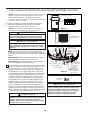
How to Wire Your Ceiling Fan
MAIN FUSE BOX
Figure 2
Figure 1
Figure 4
Green Wire
from Supply
(Ground)
White Wire
from Supply
White Wire
from Receiver
Green Wire
from Hanger
Bracket (Ground)
Green Wire
from Hanger
Ball (Ground)
Listed
Outlet Box
Household
Supply
Black Wire
from Supply
Black Wire
from Receiver
Receiver
Figure 3
x 6WIRE
CONNECTORS
HARDWARE USED:
Bl
ue to
Li
g
ht
Bl
ac
k t
o
M
o
t
or
Whit
e
t
o
M
o
t
or
all
To avoid possible electrical shock, be sure electricity
is turned off at the main fuse box before wiring
(Figure 2).
WARNING
NOTE:
If you are not sure if the outlet box is
grounded, contact a licensed electrician for advice, as
it must be grounded for safe operation.
NOTE:
If you feel that you do not have enough electrical
wiring knowledge or experience, have your fan installed
by a licensed electrician.
Check to see that all connections are tight, including
ground, and that no bare wire is visible at the wire
connectors except for the ground wire. Do not
operate fan until the blades are in place. Noise and
motor damage could result.
WARNING
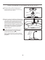
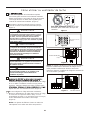
3. After connections have been made, turn leads
upward and carefully push leads into the outlet
box, with the white and green leads to one side
of the box and the black leads to the other side.
(Figure 4)
CAUTION: INCORRECT WIRE CONNECTION WILL
DAMAGE THIS RECEIVER.
2. Connect green wires from hanger bracket and
downrod to bare (ground) wire using wire connector.
Connect black wire from receiver unit marked “AC IN L”
to black supply wire using wire connector. Connect white
wire from receiver unit marked “AC IN N” to white supply
wire using wire connector. Connect white wire from
receiver unit marked “TO MOTOR N” to white wire from
fan using wire connector supplied with receiver unit.
Connect black wire from receiver unit marked “TO
MOTOR L” to black wire from fan using wire connector
supplied with receiver unit. Lastly, connect blue wire
from receiver unit to the blue fan light wire using wire
connector supplied with receiver unit. (Figure 3)
1. To set the code on receiver unit, slide dip switches to
the same positions as set on the remote. (Figure 1)
NOTE: The remote unit has 32 different code
combinations. To prevent possible interference from or to
other remote units, simply change the combination code
in the remote and receiver.
NOTE: Factory setting is all up. Do not use this position.
10
Dip Switch
ON DIP
1 2 3 4 5
Receiver Unit

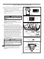
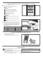
How to Install Your Canopy Housing
How to Assemble Your Light Kit and Glass
2. Securely attach and tighten the canopy screw cover
over the shoulder screws in the hanger bracket utilizing
the keyslot twist-lock feature. (Figure 2)
1. Remove one of the two shoulder screws in the
hanger bracket. Loosen the second shoulder screw
without fully removing it. Assemble canopy by
rotating key slot in canopy over shoulder screw in
hanger bracket. Tighten shoulder screw. Fully
assemble and tighten second shoulder screw that
was previously removed. (Figure 1)
WARNING
To avoid possible fire or shock, make sure that the
electrical wires are completely inside the canopy
housing and not pinched between the housing and the
ceiling.
NOTE: This step is applicable after the neccessary
wiring is completed.
Canopy Screw
Cover
Ceiling
Canopy
Figure 1
11
Figure 2
Figure 2
Motor
Assembly
1. Remove one of the three screws in the support
bracket at the bottom of the motor assembly and
retain the screw for later. Slightly loosen the
remaining two screws. (Figure 1)
To Reduce The Risk Of Electric Shock, Disconnect
The Electrical Supply Circuit To The Fan Before
Installing Light Kit.
CAUTION
2. Assemble the light kit to the motor assembly
support bracket using the two key slots in the
light kit. Replace the previously removed screw and
securely tighten all three screws. (Figure 2)
Light Kit
Figure 1

Light Kit
Light Kit
Light Kit
Figure 3
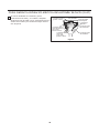
How to Assemble Your Light Kit and Glass (continued)
12
Figure 4
Figure 5
Figure 6
Glass
3. Remove one of the three screws in the light kit
and retain the screw for later. Slightly loosen the
remaining two screws. (Figure 3)
5. Assemble the light plate/LED assembly to the light
kit using the two key slots and replace the third screw
and securely tighten all three screws. (Figure 5 )
The light source is designed for this specific
application and can overheat if serviced by untrained
personnel. If any servicing is required, the product
should be returned to an authorized service facility
for examination or repair.
CAUTION
6. Secure the glass to the light kit by twisting in a
clockwise direction. Do not over-tighten. (Figure 6)
Motor
Assembly
Light Plate/LED
Assembly
Light Plate/LED
Assembly
4. Securely attach 9-pin connector from motor
assembly to wiring harness socket within light plate/
LED assembly. (Figure 4)
WARNING
The color label on these two connectors must correspond
to each other.

How to Operate Your Ceiling Fan
Figure 2
MAIN FUSE BOX
Figure 1
For illustrative purposes only-not
intended to cover all types of controls
2. Restore electrical power to the outlet box by turning
the electricity on at the main fuse box. (Figure 2)
Check to see that all connections are tight, including
ground, and that no bare wire is visible at the wire
connectors, except for the ground wire. Do not
operate fan until the blades are in place. Noise and
fan damage could result.
WARNING
1. IMPORTANT: Using a full range dimmer switch
(not included) to control fan speed will damage the fan.
To reduce the risk of fire or electrical shock, do not use
a full range dimmer switch to control the fan speed.
(Figure 1)
WARNING
Do not operate this fan with a variable (Rheostat) wall
controller or dimmer switch. Doing so could result in
damage to the ceiling fan's remote control unit.
13
3. To make fan operational, install 23A/12V battery
(included) in hand-held remote transmitter, with fan
power off. Then follow the remote code setting
process. (If not used for long periods of time, remove
battery toprevent damage to transmitter). Store the
remote away from excessive heat or humidly.
(Figure 3)
NOTE: The remote unit has 32 different code
combinations. To prevent possible interference from or
to other remote units, simply change the combination
code in the remote and receiver.
4. To set the remote code with a small screwdriver or
ball point pen (neither included), slide dip switches
firmly up or down. (Figure 4)
NOTE: Factory setting is all up. Do not use this
position.
Figure 4
Dip Switch
ON DIP
1 2 3 4 5
Remote
12V 23A
Battery (1 pcs)
Figure 3

How to Operate Your Ceiling Fan (continued)
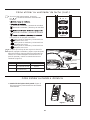
5. Remote functions: (Figure 5)
,QGLFDWRU/('OLJKWIDQVSHHG
EXWWRQ7XUQVIDQRII
)DQ6SHHG
7XUQVIDQRQDQGWXUQVVSHHGXS
7XUQVIDQRQDQGWXUQVVSHHGGRZQ
/LJKWEXWWRQ7XUQVOLJKWRQDQGRII
,QFUHDVHVOLJKWRXWSXWOHYHO
'HFUHDVHVOLJKWRXWSXWOHYHO
7DSDQGWKHIDQDQGOLJKWZLOOWXUQRIIDIWHU
KRXUV
7DSDQGWKHIDQDQGOLJKWZLOOWXUQRIIDIWHU
KRXUV
7DSDQGWKHIDQDQGOLJKWZLOOWXUQRIIDIWHU
KRXU
6HDVRQ
6XPPHU
Winter
5RWDWLRQ'LUHFWLRn 6ZLWFK3RVLWLRQ
&ORFNZLVH
&RXQWHUFORFNZLVe
5HYHUVH6ZLWFK,QIRUPDWLRQ
5LJKW
/HIW
6.,IDLUIORZLVGHVLUHGLQWKHRSSRVLWHGLUHFWLRQWXUQ
WKHIDQRIIDQGZDLWIRUWKHEODGHVWRVWRSWXUQLQJ
7KHQVOLGHWKHUHYHUVHVZLWFKRQOLJKWSODWH/('
DVVHPEO\WRWKHRSSRVLWHSRVLWLRQDQGWXUQIDQRQ
DJDLQ)LJXUH
Figure 5
5HYHUVLQJ
6ZLWFK
Figure 6
OLJKWSODWH/('
$VVHPEO\
14
Maintenance
1. \OnoeKtsinDfgniOiecZenruo\fogninDeOcciGoire3
PDLQWHQDQFHWKDWLVQHHGHG
:KHQ FOHDQLQJ use RQO\ D soft EUXVK or OLQW free FORWK
Ksinif eKtgniKctDrcsGioYDot
$EUDVLYH FOHDQLQJ DJHQWV DUH not UHTXLUHG DQG VKRXOG
EHDYRLGHGWRSUHYHQWGDPDJHWo ILQLVK
CAUTION
Do not use solvents when cleaning your ceiling fan. It
could damage the motor or the blades and create the
possibility of electrical shock.
How to Install Your Remote Control
1. Installing Wall Holder: (Figure 1)
$WWDFKZDOOKROGHUXVLQJWKHWZRSURYLGHGVFUHZV
Figure 1

15
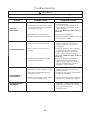
Troubleshooting
For your own safety turn off power at fuse box or circuit breaker before trouble shooting your fan.
WARNING
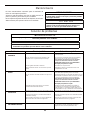
Trouble Probable Cause Suggested Remedy
1.FAN WILL
NOT START
1. Check main and branch circuit fuses
or circuit breakers.
2. Check line wire connections to fan
and switch wire connections in the
switch housings.
CAUTION: Make sure main power is
turned off !
1. Fuse or circuit breaker blown.
2. Loose power line connections to the
fan, or loose switch wire connections
in the switch housing.
2.FAN SOUNDS NOISY
1. Check to make sure all screws in
motor housing are snug (do not
overtighten).
2. Check to make sure wire connectors
in switch housing are not rattling
against each other or against the
interior wall of the switch housing.
CAUTION: Make sure main power is
turned off !
3. Some fan motors are sensitive to
signals from solid-state variable
speed controls. Solid-state controls
are not recommended, choose an
alternative control method.
1. Loose screws in motor housing.
2. Wire connectors inside housing
rattling.
3. Motor noise caused by solid state
variable speed control.
3.FAN WOBBLES
EXCESSIVELY
1. Tighten both setscrews securely in
downrod support.
2. Tighten the setscrew in the downrod/
hanger ball assembly.
3. Tighten the hanger bracket screws to
the outlet box, and secure outlet box.
1. Setscrew in downrod support is loose.
2. Setscrew in downrod/hanger ball
assembly is loose.
3. Hanger bracket and/or ceiling outlet
box is not securely fastened.
4.NOT ENOUGH AIR
MOVEMENT
3. Dead battery in remote control. 3. Replace with new battery.
1. If possible, consider using a longer
downrod (not included, you can buy
the longer downrod from
fanimation.com).
4. Make sure reversing switch position is
all the way to one side.
4. Reversing switch in neutral position.

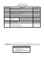
Reference # Description # traP
1
ADR1-45BL
2
P799301BL
3
4
APPCP1403BLMotor Coupling Cover Assembly
5
AMA8519BL
Light Kit/Glass Assembly
Motor Assembly
6
TR500
7
RCCA01001500
AP255BL
AP260BL
Receiver Unit
Hand-Held Remote
9
8
11
10
HDWFP8519
Hanger Bracket Assembly
Hanger Ball/Downrod Assembly
Ceiling Canopy
Canopy Screw Cover Assembly
16
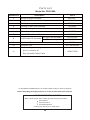
Parts List
Model No. FP8519BL
HOW TO ORDER REPAIR PARTS
When ordering repair parts, always give the following information:
Part Number
Part Description
Fan Model Number
Contact your retail store for repair parts.
Before discarding packaging material, be certain all parts have been removed.
** Insert FINISH CODES (Refer to fan model number located on downrod support)
AP851911BL
AP851912BL
AP845810
Hardware Bag Containing:
Wire Connectors (4)
Bag Assembly Safety Cable
Light Plate/LED Assembly
8a-Light Plate Assembly
8b-LED Assembly

17
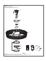
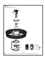
Model FP8519BL
Exploded-View Illustration
NOTE: The illustration shown is not to scale or its actual con guration may vary.
Product/parts are subject to change without notice.
Figure 1
1
2
3
4
5
6
7
8a
8b
Henry
™
11
11
109

Copyright 2019 Fanimation
2019/01 V.01
10983 Bennett Parkway
Zionsville, IN 46077
Phone: 888-567-2055
Outside U.S.: 317-733-4113
FANIMATION.COM
FAX: 866-482-5215

ADJUNTE SU RECIBO AQUÍ Y REGISTRE SU VENTILADOR EN FANIMATION.COM
LEA Y GUARDE ESTAS INSTRUCCIONES
Peso neto 7.20 kg (15.88 lbs)
Preguntas, problemas, piezas faltantes? Antes de volver a la tienda, llame a nuestro
Departamento de Servicio al Cliente al 1-888-567-2055, 8 a.m. - 5 pm, hora del Este, de
lunes - viernes.
Número de serie
Fecha de compra
MODELO #FP8519BL
™
VENTILADOR DE TECHO HENRY

ADVERTENCIA:
Instrucciones de seguridad importantes
ADVERTENCIA: Siga estas instrucciones para prevenir incendios, descargas eléctricas y lesiones personales graves.
Lea el manual del propietario y la información de seguridad antes de instalar su nuevo ventilador. Observe los diagramas de 1.
ensamblaje adjuntos.
Antes de llevar a cabo el mantenimiento o la limpieza de la unidad, desconecte la electricidad en el panel de servicio y bloquee los
2.
medios de desconexión del mismo para evitar que se active accidentalmente. Si no se pueden bloquear los medios de desconexión
del servicio, coloque un dispositivo de advertencia, como una etiqueta, en el panel de servicio.
Tenga cuidado con la estructura y las aspas del ventilador cuando limpie, pinte o trabaje cerca del mismo. Desconecte siempre la
3.
electricidad del ventilador de techo antes de llevar a cabo el mantenimiento.
No coloque nada en las aspas del ventilador cuando éste se encuentra en funcionamiento.
4.
Instrucciones de seguridad adicionales
Para evitar posibles descargas eléctricas, asegúrese de que la electricidad esté desconectada en la caja de fusibles antes de realizar1.
la instalación eléctrica, y no haga funcionar el ventilador sin las aspas.
Todos los procedimientos de conexión eléctrica e instalación deben cumplir con los Códigos eléctricos nacionales (ANSI/NFPA
2.
70) y Códigos locales. El ventilador de techo debe estar conectado a tierra a fin de prevenir posibles descargas eléctricas. La
instalación eléctrica debe ser llevada a cabo o aprobada por un electricista autorizado.
Se debe fijar bien la base del ventilador; ésta debe ser capaz de soportar sin problemas al menos 15,9 kg (35 lb). Consulte la página
3.
24 del manual del propietario para ver los requisitos de soporte. Si tiene dudas, consulte a un electricista calificado.
Las aspas del ventilador deben instalarse por lo menos a 2,13 m (7 pies) del suelo, a fin de evitar un contacto accidental con las mismas.
4.
Siga las recomendaciones sobre el método correcto de instalación eléctrica de su ventilador de techo. Si no posee la experiencia o 5.
los conocimientos eléctricos adecuados, contrate a un electricista autorizado para instalar el ventilador.
Apto para usar con controles de velocidad de estado sólido.
6.
ADVERTENCIA: Monte a una caja de salida aceptable para apoyo de los aficionados.
PARA REDUCIR EL RIESGO DE DESCARGAS ELÉCTRICAS, ESTE VENTILADOR SE DEBE INSTALAR CON UN
CONTROL/INTERRUPTOR DE PARED AISLADO.
ADVERTENCIA: Este producto está diseñado para ser usado sólo con las piezas suministradas o los accesorios indicados
específicamente para el mismo. Si utiliza piezas o accesorios que no están indicados para su uso con este producto, podría
sufrir lesiones personales o dañar el ventilador. ADVERTENCIA: Este producto está diseñado para ser usado sólo con las piezas
suministradas o los accesorios indicados específicamente para el mismo. Si utiliza piezas o accesorios que no están indicados para su
uso con este producto, podría sufrir lesiones personales o dañar el ventilador.
ADVERTENCIA: Para reducir el riesgo de lesiones personales, no doble los soportes de las aspas (borde o soporte de aspas) al instalar
los soportes, balancear las aspas o limpiar el ventila
dor. No coloque objetos extraños entre las aspas del ventilador en funcionamiento.
(1) Este equipo no causará interferencias perjudiciales y (2) este equipo tolerará cualquier interferencia recibida, incluidas las
interferencias que puedan provocar un funcionamiento no deseado. Si el radiador intencional puede ser clasificado como un
dispositivo digital de clase B o un periférico del ordenador, entonces se deberán incluir los siguientes o equivalentes:
Nota: Tras someterlo a las pruebas correspondientes, se ha determinado que este equipo cumple con los límites establecidos para
dispositivos digitales de Clase B de conformidad con la parte 15 de la Normativa FCC. Estos límites se han establecido con el objetivo
de aportar una protección razonable contra interferencias perjudiciales cuando el equipo se utiliza en el hogar. Este equipo genera,
utiliza y puede emitir energía de radiofrecuencia y, a menos que se instale y se utilice de acuerdo con el manual de instrucciones, puede
provocar interferencias perjudiciales en las comunicaciones por radio y televisión. Si el equipo produce interferencias perjudiciales en la
recepción de radio o televisión, lo cual puede probarse encendiendo y apagando el equipo, se recomienda al usuario corregir dichas
interferencias tomando una o varias de las siguientes medidas:
- Modificar la orientación o ubicación de la antena de recepción;
- Aumentar la separación entre el equipo y el receptor;
- Conectar el equipo a una toma de corriente o circuito diferente al del receptor;
Consulte al distribuidor o a un técnico especialista de radio o TV para obtener más ayuda.
Nota: Para un dispositivo digital de clase A, la declaración de 15. 105(a) debe ser incluida cuando sea apropiada para el dispositivo en
cuestión.
5. El dispositivo no ha sido diseñador para ser utilizado por niños o personas enfermas sin supervisión. Los niños deben ser supervisados
para asegurarse de que no juegan con el dispositivo.
7. Este ventilador es apto sólo para lugares secos o húmedos.
8. En lo que respecta a las conexiones de suministro, si el conductor del ventilador está identificado como conductor con conexión a tierra,
se le debe conectar a un suministro de electricidad con conductor de puesta a tierra. Si el conductor del ventilador está identificado
como conductor que no es de puesta a tierra, se le debe conectar a un suministro de electricidad con conductor sin puesta a tierra.
Si el conductor del ventilador está identificado para equipos de puesta a tierra, se le debe conectar al conductor de equipos de puesta
a tierra.
ADVERTENCIA: No utilice este ventilador con un controlador variable de pared (Rheostat) o un regulador de intensidad. Si lo hiciera
podría dañar la unidad del mando a distancia del ventilador de techo.
AVERTISSEMENT: CE VENTILATEUR DOIT ÊTRE INSTALLÉ AVEC UNE COMMANDE/INTERRUPTEUR MURAL ISOLANT À
USAGE GÉNÉRAL AFIN DE RÉDUIRE LES RISQUES D'ÉLECTROCUTION.
AVERTISSEMENT: Ce produit est conçu pour utiliser uniquement les pièces l'accompagnant et/ou les accessoires spécifiquement
conçus pour ce produit. L'utilisation de pièces et/ou d'accessoires qui ne sont pas conçus pour être utilisés avec ce produit peut
provoquer des blessures ou des dommages matériels.
AVERTISSEMENT: Afin de réduire le risque de blessure, ne pliez pas le support de pale (bride ou porte-pale) lors de l'installation des
supports, de l'équilibrage des pales ou du nettoyage du ventilateur. N'insérez pas de corps étrangers entre les pales du ventilateur en
rotation.
AVERTISSEMENT:
AVERTISSEMENT: Montez sur une boîte de sortie indiquée comme étant acceptable pour supporter un ventilateur.
N'utilisez pas ce ventilateur avec un contrôleur mural (rhéostat) variable ou un gradateur. Cela pourrait endommager la
télécommande du ventilateur de plafond.
La page est en cours de chargement...
La page est en cours de chargement...
La page est en cours de chargement...
La page est en cours de chargement...
La page est en cours de chargement...
La page est en cours de chargement...
La page est en cours de chargement...
La page est en cours de chargement...
La page est en cours de chargement...
La page est en cours de chargement...
La page est en cours de chargement...
La page est en cours de chargement...
La page est en cours de chargement...
La page est en cours de chargement...
La page est en cours de chargement...
La page est en cours de chargement...
La page est en cours de chargement...
La page est en cours de chargement...
-
 1
1
-
 2
2
-
 3
3
-
 4
4
-
 5
5
-
 6
6
-
 7
7
-
 8
8
-
 9
9
-
 10
10
-
 11
11
-
 12
12
-
 13
13
-
 14
14
-
 15
15
-
 16
16
-
 17
17
-
 18
18
-
 19
19
-
 20
20
-
 21
21
-
 22
22
-
 23
23
-
 24
24
-
 25
25
-
 26
26
-
 27
27
-
 28
28
-
 29
29
-
 30
30
-
 31
31
-
 32
32
-
 33
33
-
 34
34
-
 35
35
-
 36
36
-
 37
37
-
 38
38


Fanimation FP8519BL Le manuel du propriétaire
- Catégorie
- Ventilateurs ménagers
- Taper
- Le manuel du propriétaire
- Ce manuel convient également à
dans d''autres langues
Documents connexes
-
Fanimation FP8018BL Le manuel du propriétaire
-
-
-
-
-
Fanimation FP8003BPN Le manuel du propriétaire
-