Fanimation FP8018BL Le manuel du propriétaire
- Catégorie
- Ventilateurs ménagers
- Taper
- Le manuel du propriétaire

Serial Number
Purchase Date
Español p. 16
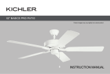
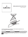
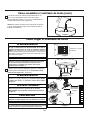
MODEL #FP8018**
™
CEILING FAN
Questions, problems, missing parts? Before returning to your retailer, call our customer
service department at 1-888-567-2055, 8 a.m.-5 p.m., EST, Monday-Friday.
ATTACH YOUR RECEIPT HERE
READ AND SAVE THESE INSTRUCTIONS
ROTATION
Net Weight : 10.21 lbs (4.63 kg)

1. LIMITED LIFETIME MOTOR WARRANTY - If any part of your fan motor fails, due to a defect in materials or workmanship during
the lifetime of the original purchaser, Fanimation will provide the replacement part free of charge, when the defective fan is returned
to our national service center. Proof of purchase is required. Customer shall be responsible for all costs incurred in the removal or
reinstallation and shipping of the product for repairs or replacement.
2. ONE YEAR MOTOR LABOR WARRANTY - If your fan motor fails at any time within one year from the original purchase, due to
defects in materials or workmanship, labor to repair the motor will be provided free of charge at our national service center. Purchaser
will be responsible for labor charges after this one-year period. Customer shall be responsible for all costs incurred in the removal or
reinstallation and shipping of the product for repairs or replacement.
3. If any other part of your fan fails at any time within one year after original purchase, due to a defect in materials or workmanship, we
will repair, or replace, at our option, the defective part free of charge for parts and labor performed at our national service center.
4. Because of varying climate conditions, this warranty does not cover changes in the finish, including rusting, pitting, corroding,
tarnishing, or peeling.
5. This warranty is void and does not apply to damage from improper installation, neglect, accident, misuse, exposure to extremes of
heat or humidity, or as a result of any modification to the original product.
6. All costs of removal and reinstallation of the fan are the sole responsibility of the owner of the fan and not the store that sold the fan
or Fanimation.
7. Fanimation reserves the right to modify or discontinue any product at any time and may substitute any part under this warranty.
8. Under no circumstances may a fan be returned without prior authorization from Fanimation. The receipt of purchase must ac-
company authorized returns and must be sent freight prepaid to Fanimation. The fan to be returned must be properly packed to avoid
damage in transit; Fanimation will not be responsible for any damage resulting from improper packaging.
9. It is understood that any repair or replacement is the exclusive remedy available from Fanimation. There is no other expressed or
implied warranty. Fanimation hereby disclaims any and all implied warranties, including, but not limited to those of merchantability and
fitness for a particular purpose to the extent permitted by law. Some states do not allow limitations on implied warranties. Fanimation
will not be liable for incidental, consequential, or special damages arising out of or in conjunction with product use or performance,
except as may otherwise be accorded by law. This warranty gives you special legal rights and you may also have other rights that vary
from state to state.
10. A certain amount of wobble is normal and should not be considered a problem or a defect.
LIMITED LIFETIME WARRANTY
Extends to the original purchaser of a Fanimation Fan
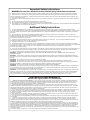
Important Safety Instructions
WARNING: To avoid fire, shock and serious personal injury, follow these instructions.
1. Read your owner’s manual and safety information before installing your new fan. Review the accompanying assembly diagrams.
2. Before servicing or cleaning unit, switch power off at service panel and lock service panel disconnecting means to prevent power
from being switched on accidentally. When the service disconnecting means cannot be locked, securely fasten a warning device, such
as a tag, to the service panel.
3. Be careful of the fan and blades when cleaning, painting, or working near the fan. Always turn off the power to the ceiling fan before
servicing.
4. Do not insert anything into the fan blades while the fan is operating.
5. Do not operate reversing switch until fan blades have come to a complete stop.
Additional Safety Instructions
1. To avoid possible shock, be sure electricity is turned off at the fuse box before wiring, and do not operate fan without blades.
2. All wiring and installation procedures must satisfy National Electrical Codes (ANSI/ NFPA 70-1999) and Local Codes. The ceiling fan
must be grounded as a precaution against possible electrical shock. Electrical installation should be made or approved by a licensed
electrician.
3. The fan base must be securely mounted and capable of reliably supporting at least 35 lbs. See page 6 of owner’s manual for
support requirements. Consult a qualified electrician if in doubt.
4. Make sure the installation site you choose allows a minimum clearance of 10 feet from the blades to the floor and at least 2.5 feet from
the ends of the blades to any obstruction.
5. Follow the recommended instructions for the proper method of wiring your ceiling fan. If you do not have adequate electrical
knowledge or experience, have your fan installed by licensed electrician.
6. The appliance is not intended for use by young children or infirm persons without supervision. Young children should be supervised to
ensure that they do not play with the appliance.
8. For supply connections, if the conductor of a fan is identified as a grounded conductor, then it should be connected to a
9. If you are mounting the fan to a ceiling outlet box, use a METAL octagonal outlet box. Secure the box directly to the building structure.
The outlet box and its support must be able to support the moving weight of the fan (at least 35 lbs.) Do NOT use a plastic outlet box.
10. After you install the fan, make sure that all connections are secure to prevent the fan from falling.
grounded
conductor power supply. If the conductor of a fan is identified as an ungrounded conductor, then it should be connected to an ungrounded
conductor power supply. If the conductor of a fan is identified for equipment grounding, then it should be connected to an
equipment grounding conductor.
7. This fan is to be used in dry and damp locations.
WARNING: TO REDUCE THE RISK OF SHOCK, THIS FAN MUST BE INSTALLED WITH A GENERAL USE ISOLATING WALL
CONTROL/SWITCH.
WARNING:
WARNING:
Do not install or use fan if any part is damaged or missing.
WARNING: To reduce the risk of fire or electric shock, this fan should only be used with Solid-State Fan Speed Control.
This product is designed to use only those parts supplied with this product and/or accessories designated specifically for
use with this product. Using parts and/or accessories not designated for use with this product could result in personal injury or property
damage.
WARNING: To reduce the risk of personal injury, do not bend the blade bracket (flange or blade holder) when installing the brackets,
balancing the blades, or cleaning the fan. Do not insert foreign objects in between rotating fan blades.
WARNING: All set screws must be checked and retightened where necessary before installation.
WARNING: (a) A lubricant should not be used on the single mounting screw; and (b) The pilot hole should be drilled no larger than the
minor diameter of the mounting screw threads, and at least 38mm (1½ inches) of the threaded part of the mounting screw should be
secured into a structural wood joist to provide secure mounting
WARNING: To reduce the risk of fire, electric shock, or personal injury, do not bend the blade arms when installing them, balancing the
blades, or cleaning the fan. Do not insert foreign objects between the rotating fan blades. Mount to outlet box marked “ACCEPTABLE
FOR FAN SUPPORT” and use mounting screws provided with the outlet box. Most outlet boxes commonly used for the support of
lighting fixtures are not acceptable for fan support and may need to be replaced. Consult a qualified electrician if in doubt.

Table of Contents
Unpacking Instructions. . . . . . . . . . . . . . . . . . . . . . . . . . .
Electrical and Structural Requirements. . . . . . . . . . . . . .
How to Assemble Your Ceiling Fan. . . . . . . . . . . . . . . . .
How to Hang Your Ceiling Fan . . . . . . . . . . . . . . . . . . . . .
How to Wire Your Ceiling Fan . . . . . . . . . . . . . . . . . . . . .
Energy Efficient Use of Ceiling Fans . . . . . . . . . . . . . . . .
4
5
5
7
8
10
Installing Your Canopy Housing . . . . . . . . . . . . . . . . . . . .
11
11
How to Operate Your Ceiling Fan . . . . . . . . . . . . . . . . . . .
Maintenance. . . . . . . . . . . . . . . . . . . . . . . . . . . . . . . . . . . . . 12
Trouble Shooting . . . . . . . . . . . . . . . . . . . . . . . . . . . . . . . . 12
Parts List . . . . . . . . . . . . . . . . . . . . . . . . . . . . . . . . . . . . . . .
Exploded-View Illustration. . . . . . . . . . . . . . . . . . . . . . . . .
13
14

This manual is designed to make it as easy as possible for you
to assemble, install, operate, and maintain your ceiling fan
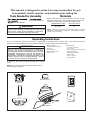
Unpacking Instructions
For your convenience, check-off each step. As each step is completed, place a check mark. This will ensure that all
steps have been completed and will be helpful in finding your place should you be interrupted.
Wiring outlet box and box connectors must be of type
required by local code. The minimum wire would be a 3-
conductor (2-wire with ground) of the following size:
NOTE: Place the parts from the loose parts bags in a small
container to keep them from being lost. If any parts are missing,
contact your local retailer.
Tools Needed for Assembly Materials
Wire Size A.W.G.Installed Wire Length
14
12
Up to 50 ft.
50 - 100 ft.
NOTE: If you are uncertain of part description, refer to
exploded view illustration.
4
1. Check to see that you have received the following
parts:
Hardware Bags
blade screwdriver
Four wire connectors
WARNING
Do not install or use fan if any part is damaged or
missing. This product is designed to use only those
parts supplied with this product and/or any accessories
designated specifically for use with this product by
Fanimation. Substitution of parts or accessories not
designated for use with this product by Fanimation could
result in personal injury or property damage. Contact
your retail store for missing or damaged parts.
WARNING
Before assembling your ceiling fan, refer to section on
proper method of wiring your fan (page 10). If you feel you
do not have enough wiring knowledge or experience,
have your fan installed by a licensed electrician.
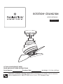
Hanger Bracket
Assembly
Downrod
Ceiling Canopy Motor Assembly
Motor Coupling Cover
Wall Control
• Motor Assembly
• Hanger Bracket Assembly
• Downrod
Ceiling Canopy•
• Motor Coupling Cover
Wall Control •
• Hardware bags:
– Four wire connectors
– 7/16˝ wrench
– 3/8˝ x 5˝ lag bolt with Flat Washer
• Support Cable bag:
– Ceiling Support Cable
– Cable Clamp
– 3/8˝ x 2˝ lag bolt
– 3/8˝ flat washer

Energy Efficient Use of Ceiling Fans
Ceiling fan performance and energy savings rely
heavily on the proper installation and use of the ceiling
fan. Here are a few tips to ensure efficient product
performance.
Turn Off When Not in the Room
Ceiling fans cool people, not rooms. If the room is
unoccupied, turn off the ceiling fan to save energy.
Using the Ceiling Fan Year Round
Summer Season: Use the ceiling fan in the counter-
clockwise direction. The airflow produced by the ceiling
fan creates a wind-chill effect, making you “feel” cooler.
Select a fan speed that provides a comfortable breeze,
lower speeds consume less energy.
Winter Season: Reverse the motor and operate the ceiling
fan at low speed in the clockwise direction. This produces
a gentle updraft, which forces warm air near the ceiling
down into the occupied space.Remember to adjust your
thermostat when using your ceiling fan - additional energy
and dollar savings could be realized with this simple step!
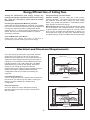
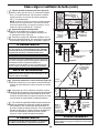
Electrical and Structural Requirements
Your new ceiling fan will require a grounded electrical
supply line of 120 volts AC, 60 HZ, 15 Amp Circuit.
Electrical code requires use of a fan-rated outlet box to
support the extra weight and motion associated with a
ceiling fan. A fan-rated box will be labeled as such and
typically supports up to a 70lb ceiling fan. Fan-Rated
Outlet Boxes vary in ratings and design. Ensure the
ratings of your ceiling fan outlet box meet the
requirements for the ceiling fan being installed. Figure 1,
Figure 2 and Figure 3 depicts different structural
configurations that may be used for mounting the
outlet box.
Low profile box (Figure 1)
A 1⁄2-in.-deep pancake box is meant to be screwed to a
joist or block. It’s used if only one cable is coming into
the box. It is also available in a saddle-mount
configuration.
CEILING
2" x 4"
CEILING JOIST
OUTLET BOX
Figure 1
Figure 2
2" x 4"
CEILING JOIST
CEILING
OUTLET BOX
Deep box (Figure 2)
A 2-1⁄4-in.-deep box can be attached to blocking
between joists and is roomy enough to handle more
than one cable.
5
Choosing the Appropriate Mounting Location
Ceiling fans should be installed, or mounted, in the middle
of the room and at least 10 feet from floor to the blade and
2.5 feet from wall to the blade. If ceiling height allows,
install the fan 10 - 11 feet from floor to the blade for optimal
airflow. Consult your Fanimation Retailer for optional
mounting accessories.

6
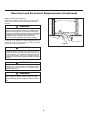
Electrical and Structural Requirements (Continued)
If your fan is to replace an existing light fixture, turn
electricity off at the main fuse box at this time and
remove the existing light fixture.
Turning off wall switch is not sufficient. To avoid
possible electrical shock, be sure electricity is
turned off at the main fuse box before wiring. All
wiring must be in accordance with National and
Local codes and the ceiling fan must be properly
grounded as a precaution against possible electrical
shock.
WARNING
WARNING
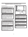
Deep box with brace (Figure 3)
Paired with a deep box, this hanger is meant to span
between two joists and takes the place of wooden
blocking.
To avoid fire or shock, follow all wiring instructions
carefully. Any electrical work not described in these
instructions should be done or approved by a
licensed electrician.
WARNING
Do not operate this fan with a variable (Rheostat)
wall controller or dimmer switch. Doing so could
result in damage to the ceiling fan's remote control
unit.
WARNING
Figure 3
CEILING JOIST
CEILING
OUTLET BOX
To reduce the risk of fire, electric shock, or personal
injury, mount to outlet box marked acceptable for fan
support of 15.9 kg (35 lbs) or less and use mounting
screws provided with the outlet box. Most outlet boxes
commonly used for the support of luminaires are not
acceptable for fan support and may need to be
replaced, consult a qualified electrician if in doubt.

7
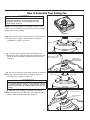
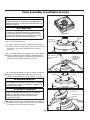
How to Assemble Your Ceiling Fan
NOTE: Do not set Ceiling Fan Assembly on fl oor or hard
surface. Prior to assembly, set aside and save the hardware
bag(s) packed in the packing.
CAUTION
To prevent damage to housing and/or blade, leave the
Ceiling Fan Assembly in its original packing during
installation of down rod, motor coupling cover and
ceiling canopy. (Figure 1)
Figure 1
Figure 2
1. Remove the hairpin clip and clevis pin from the bottom
of the downrod support . Retain the pin and clip for
reinstallation in Step 3. (Figure 2)
Figure 3
2. The fan comes with black, white and green wires ,
as well as a safety cable. Separate and untwist the wires.
Route the wires and safety cable through the downrod.
(Figure 3)
Line up the
holes for clevis
pin installation
Figure 4
Black, White, Green
and Safety Cable
3. Be sure to line up the holes while pushing the downrod
into the downrod support prior to installing clevis pin
and hairpin clip. (Figure 3 & Figure 4)
▲
WARNING
It is critical that the clevis pin in the downrod support
is properly installed. Failure to verify that the pin and
hairpin clip are properly installed could result in the fan
falling.
Figure 5
Motor Coupling
Cover
Ceiling Canopy
4. Slide the motor coupling cover down the downrod
until it touches the top of the motor, then slide the ceiling
canopy down the downrod as well. (Figure 5)
Hairpin Clip
Hairpin Clip
Clevis Ping
Clevis Ping

Figure 1
Figure 2
MAIN FUSE BOX
8
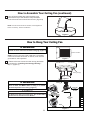
How to Assemble Your Ceiling Fan (continued)
Figure 6
5. Cut off excess lead wire approximately 6 to 9
inches above top of the downrod. Strip insulation
1/2 inch from the end of each lead off wire. (Figure 6)
1. Remove the two screws from the canopy and retain
the screws for “ Installing the Canopy Housing ”
Step 1. (Figure 2)
NOTE:
All set screws must be checked, and retightened
where necessary, before installation.
Figure 3
No
less than
10 ft
2.5 ft min.
from
staircase
or wall
WARNING:
Do NOT
Mount Fan
On Wall
Or Floor!
Floor
Ceiling
How to Hang Your Ceiling Fan
▲
WARNING
To avoid possible electrical shock, be sure electricity is
turned off at the main fuse box before hanging. (Figure 1)
▲
WARNING
The fan must be hung with at least 10´ of clearance from
floor to blade and MUST ONLY be hung in a vertical
downward position from ceiling. (Figure 3)
CAUTION
To Reduce the Risk of Personal Injury, this Product Must
be Secured as Described in the Manual.
NOTE:
If you are not sure if the outlet box is grounded,
contact a licensed electrician for advise, as it must be
grounded for safe operation.
Ceiling Canopy

Figure 4
Junction
Box
Ceiling
Support
Cable
Ceiling Joist
Wood Member
(2” x 4” Approx.)
Hanger Bracket
Ceiling
2. Attaching Ceiling Support Cable (Figure 4): Drill
¼˝ pilot hole through into the ceiling joist or structural
member. Securely attach the ceiling support cable with
3
⁄8˝ x 2˝ lag bolt and fl at washer.
NOTE: Ceiling support cable must be directly secured
to ceiling joist or structural member between fl at washer
and junction box with 2˝ lag bolt (Figure 4).
3.
Hanger Bracket Attachment:
Securely attach the hanger bracket to the outlet box
using the outlet box screws and washers supplied with
the outlet box (Figure 4).
9
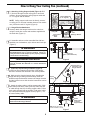
How to Hang Your Ceiling Fan (continued)
Figure 5
Figure 6
Downrod
(Assembled Fan)
Loosen Nuts on
both sides of the
Hanger Bracket
Sloped
Ceiling
Figure 7
4. Assemble and secure the assembled fan with hex-
head bolt, two lockwashers, nylon locknut and clevis pin.
(Figure 5)
5. (Optional)
Sloped Ceiling Installation (Figure 6)
:
Loosen two nuts located on both sides of the hanger
bracket to orientate the downrod in the vertical position.
6. Make sure the electrical supply wires, including the
hanger bracket grounding wire and safety cable are
pulled through the downrod, between the hanger bracket
and the junction box so that electrical connections can be
made later.
INSTALLATION NOTE
The hanger bracket angle adjustment MUST ONLY be
used to orientate the downrod in a vertical downward
position.
▲
WARNING
It is critical that the clevis pin and lock nut in the hanger
bracket/downrod area is properly installed. Failure to
verify that the nut and hairpin clip are properly installed
could result in the fan falling.
7. Attach the safety cable to ceiling support cable. Slide
cable clamp onto safety cable (from fan). Place the end
of cable through the loop of ceiling support cable. Pull as
much cable through loop as possible. Feed end of cable
into clamp hole and fi rmly tighten screw (Figure 7). Cut
off excess safety cable.
▲
WARNING
To avoid possible shock, do not pinch wires between the
downrod and the hanger bracket.
NOTE: Supply wires and
fan wires omitted for clarity
Attach
Safety Cable
to Ceiling
Support Cable

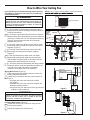
How to Wire Your Ceiling Fan
If you feel that you do not have enough electrical wiring
licensed electrician.
NOTE: If fan or supply wires are different colors than indicated,
▲
WARNING
To avoid possible electrical shock, be sure electricity is
turned off at the main fuse box before wiring. (Figure 1)
NOTE: If you are not sure if the outlet box is grounded,
contact a licensed electrician for advice, as it must be
grounded for safe operation.
Figure 2
Figure 1
Figure 3
Figure 4
knowledge or experience, have your fan installed by a
10
6. The wires should be spread apart with the grounded
conductor and the equipment-grounding conductor on
one side of the outlet box and the ungrounded
conductor on the other side of the outlet box.
1. Run the black, white and green wires through the
wiring hole in the side of the hanger bracket to allow for
electrical connections.
2. Connect the green grounding wire from the fan and
hanger bracket to the grounding wire from the outlet box
(this may be a bare wire or a wire with green insulation).
Securely connect these wires with wire connector
supplied with your fan.
3. Securely connect the white wire from the fan motor
to the white supply (neutral) wire using wire connector
supplied. (Figure 2)
4. Securely connect the black fan motor wire to the
black supply wire using wire connector supplied.
(Figure 2)
5. After connections have been made, turn leads
upward and carefully push leads into the outlet box,
with the white and green leads to one side of the box
and the black leads towards the other side.
120 VAC
Supply
(User
Supplied)
Black Wire
(Hot)
White
(Neutral)
Green Wire
(Ground)
(To/From
hanger
bracket
and fan)
▲
WARNING
Check to see that all connections are tight, including
ground, and that no bare wire is visible at the wire
connectors, except for the ground wire.
Hanger Bracket
Assembly
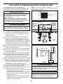
Wiring Wall Control (Figure 3):
Installing Wall control (Figure 4):
• With electrical power still disconnected, remove the
existing wall plate and switch.
• Make wiring connections with wire nuts as shown in
Figure 3.
– One black wire from wall control unit to black
(hot supply).
– One black wire from wall control unit to black wire
leading to ceiling outlet box.
– One green wire from wall control unit to ground wire
leading to ceiling outlet box.
MAIN FUSE BOX
• Attach wall control unit to outlet box using the two
6-32 screws provided.
• Attach face plate to the switch control.
WH-TO MOTOR
BLK-TO MOTOR
TO HOT
BLK TO FAN
GRN
TO GROUND
BLK
GRN
WH
BLK
120 VAC SUPPLY
(User Supplied)
GRN from hanger ball
GRN from bracket
Ceiling Fan

Figure 1
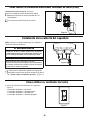
1. Wall Control Functions: (Figure 1)
How to Operate Your Ceiling Fan
11
Figure 2
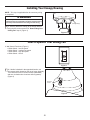
Installing Your Canopy Housing
1. Securely attach the canopy to the hanger bracket
using the two screws removed in “How to Hang Your
Ceiling Fan” step 2. (Figure 1)
NOTE: This step is applicable after the necessary wiring
is completed.
▲
WARNING
To avoid possible fire or shock, make sure that the
electrical wires are completely inside the canopy housing
and not pinched between the housing and the ceiling.
2. If airflow is desired in the opposite direction, use
the reverse switch located on the top of motor assembly.
Turn clockwise once for summer airflow (downward)
and turn clockwise twice for winter airflow (upward).
(Figure 2)
Reverse
Switch
Figure 1
Ceiling Canopy
• 3 Slide Switch – low fan speed
• 2 Slide Switch – medium fan speed
• 1 Slide Switch – high fan speed
• 0 Slide Switch – fan off

12
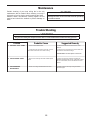
Maintenance
Periodic cleaning of your new ceiling fan is the only
maintenance that is needed. When cleaning, use only a
soft brush or lint free cloth to avoid scratching the fi nish.
Abrasive and/or non-abrasive cleaning agents are not
required and should be avoided to prevent damage to
fi nish.
CAUTION
Do not use water when cleaning your ceiling fan. It could
damage the motor or the finish and create the possibility
of electrical shock.
Trouble Shooting
▲
WARNING
For your own safety turn off power at fuse box or circuit breaker before trouble shooting your fan.
Trouble Probable Cause Suggested Remedy
1. FAN WILL NOT START
1. Fuse or circuit breaker blown.
2. Loose power line connections to the fan, or loose
switch wire connections in the switch housing.
1. Check main and branch circuit fuses or circuit
breakers.
2. Check line wire connections to fan and switch wire
connections in the switch housings.
CAUTION: Make sure main power is turned off !
2. FAN SOUNDS NOISY
1. Motor noise caused by solid state variable speed
control.
1. Some fan motors are sensitive to signals from
solid-state variable speed controls. Solid-state controls
are not recommended, choose an alternative control
method.
3. FAN WOBBLES
EXCESSIVELY
1. Clevis nut in hanger bracket/downrod is loose. 1. Tighten clevis nut securely in hanger bracket/
downrod support.

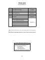
13
1 Hanger Bracket with Screws AP1160BL
2 Downrod
3 Ceiling Canopy
4 Motor Coupling Cover
5 Motor Assembly
6 Blade Assembly
DR1-4.5**
P801816**
AP801802**
AMA8018F**
AP801817**
7 Wall Control CWFP8018
8
Hardware Bag Containing:
HDWFP8018
7/16˝ Wrench (2)
⅜˝ x 5˝ Lag Bolt with Flat Washer
Wire Connectors (4)
Support Cable Bag Containing:
Ceiling Support Cable with Cable Clamp
⅜ ˝ x 2˝ Lag Bolt
Flat Washer
Before discarding packaging materials, be certain all parts have been removed
Parts List
Insert FINISH CODES (Refer to fan model number located on downrod support)
Model #FP8018**
How To Order Parts
When ordering repair parts, always
give the following information:
• Part Number
• Part Description
• Fan Model Number
Contact your retail store for repair parts.
Ref.# Part #Description

14
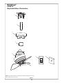
NOTE: The illustration shown is not to scale or its actual confi guration may vary.
Wires partially removed for clarity.
FP8018**
Exploded-View Illustration
Rotation
™
Figure 1
5
2
87
6
3
4
1

Copyright 2018 Fanimation
2018/01 V.01
10983 Bennett Parkway
Zionsville, IN 46077
Phone: 888-567-2055
Outside U.S.: 317-733-4113
FANIMATION.COM
FAX: 866-482-5215

Número de serie
Fecha de compra
MODELO #FP8018**
VENTILADOR DE TECHO ROTATION
™
ADJUNTE SU RECIBO AQUÍ Y REGISTRE SU VENTILADOR EN FANIMATION.COM
LEA Y GUARDE ESTAS INSTRUCCIONES
Peso neto 4.63 kg (10.21 lbs)
Preguntas, problemas, piezas faltantes? Antes de volver a la tienda, llame a nuestro
Departamento de Servicio al Cliente al 1-888-567-2055, 8 a.m. - 5 pm, hora del Este, de
lunes - viernes.

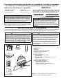
Instrucciones de seguridad importantes
ADVERTENCIA: Siga estas instrucciones para prevenir incendios, descargas eléctricas y lesiones personales graves.
Lea el manual del propietario y la información de seguridad antes de instalar su nuevo ventilador. Observe los diagramas de 1.
ensamblaje adjuntos.
Antes de llevar a cabo el mantenimiento o la limpieza de la unidad, desconecte la electricidad en el panel de servicio y bloquee los 2.
medios de desconexión del mismo para evitar que se active accidentalmente. Si no se pueden bloquear los medios de desconexión
del servicio, coloque un dispositivo de advertencia, como una etiqueta, en el panel de servicio.
Tenga cuidado con la estructura y las aspas del ventilador cuando limpie, pinte o trabaje cerca del mismo. Desconecte siempre la 3.
electricidad del ventilador de techo antes de llevar a cabo el mantenimiento.
No coloque nada en las aspas del ventilador cuando éste se encuentra en funcionamiento.4.
6. El dispositivo no ha sido diseñador para ser utilizado por niños o personas enfermas sin supervisión. Los niños deben ser supervisados
para asegurarse de que no juegan con el dispositivo.
No accione el conmutador inversor hasta que las aspas del ventilador se hayan detenido por completo.5.
.
Instrucciones de seguridad adicionales
1. Para evitar posibles descargas eléctricas, asegúrese de que la electricidad esté desconectada de la caja de fusibles antes de
realizar la instalación eléctrica, y no haga funcionar el ventilador sin las aspas.
2. Todos los procedimientos de conexión eléctrica e instalación deben cumplir con los Códigos Eléctricos Nacionales (ANSI/NFPA
70-1999). Utilice el Código Eléctrico Nacional si no existen Códigos Locales. El ventilador de techo debe estar conectado a tierra a fin
de prevenir posibles descargas eléctricas. La instalación eléctrica debe ser llevada a cabo o aprobada por un electricista autorizado.
3. Se debe fijar bien la base del ventilador; ésta debe ser capaz de soportar sin problemas al menos 15,9 kg (35 lb). No se pueden
4. Asegúrese de que el sitio de instalación que elija permita una distancia mínima de 3,05 m desde las aspas hasta el piso y de que los
extremos de las aspas estén, como mínimo, a 76,20 cm de cualquier obstáculo.
utilizar cajas de distribución eléctrica como soporte del ventilador. Consulte la página 19 del manual del propietario para ver los requisitos
5. Siga las recomendaciones sobre el método correcto de instalación el éctrica de su ventilador de techo. Si no posee la experiencia o
los conocimientos eléctricos adecuados, contrate a un electricista autorizado para instalar el ventilador.
7. Este ventilador se va a utilizar en lugares mojados.
8. En lo que respecta a las conexiones de suministro, si el conductor del ventilador está identificado como conductor con conexión a tierra,
se le debe conectar a un suministro de electricidad con conductor de puesta a tierra. Si el conductor del ventilador está identificado
como conductor que no es de puesta a tierra, se le debe conectar a un suministro de electricidad con conductor sin puesta a tierra.
Si el conductor del ventilador está identificado para equipos de puesta a tierra, se le debe conectar al conductor de equipos de puesta
a tierra.
9. Si desea montar el ventilador en una caja de salida del techo, use una caja de salida octogonal de METAL. Asegure la caja directamente
a la estructura del edificio. La caja de salida y su soporte deben ser capaces de sostener el peso del ventilador en movimiento
(como mínimo 15,88 kg). NO use una caja de salida de plástico.
10. Una vez instalado el ventilador, asegúrese de que todas las conexiones sean seguras a fin de evitar que se caiga.
ADVERTENCIA: PARA REDUCIR EL RIESGO DE DESCARGAS ELÉCTRICAS, ESTE VENTILADOR SE DEBE INSTALAR CON UN
CONTROL/INTERRUPTOR DE PARED AISLADO.
ADVERTENCIA: este producto está diseñado para ser utilizado sólo con
ADVERTENCIA: no instale ni use el ventilador si falta alguna pieza o si éstas están dañadas.
las piezas suministradas o los accesorios indicados
específicamente para el mismo. Si utiliza piezas o accesorios que no están indicados para su uso con este producto podría sufrir
lesiones personales o dañar el ventilador.
ADVERTENCIA: a fin de reducir el riesgo de incendios o descargas eléctricas, este ventilador sólo debe utilizarse con controles de
velocidad de estado sólido.
ADVERTENCIA: se deben revisar todos los tornillos y volver a ajustarlos según sea necesario antes de realizar la instalación.
ADVERTENCIA: (a) No se debe utilizar lubricante en el tornillo de montaje; y b) el orificio guía no debe ser mayor que el diámetro más
ADVERTENCIA: para reducir el riesgo de incendios, descargas eléctricas o lesiones personales, no doble los brazos de las aspas al
instalarlas, al equilibrarlas o al limpiar el ventilador. No introduzca objetos extraños entre las aspas en movimiento. Instale en una
caja de salida marcada como “ACCEPTABLE FOR FAN SUPPORT” (APTA PARA SOPORTE DE VENTILADOR) y use los tornillos de
montaje que se proporcionan con la caja de salida. La mayoría de las cajas de salida que se usan comúnmente para sostener
ensambles de iluminación no son aptas para sostener un ventilador y puede ser necesario reemplazarlas. Si tiene dudas, consulte con un
electricista calificado.
pequeño de la rosca del tornillo de montaje, y al menos 38 mm (1 ½ pulgadas) de la parte roscada del tornillo debe estar fijada en una
viga de madera estructural, a fin de asegurar una instalación segura.
AVERTISSEMENT: CE VENTILATEUR DOIT ÊTRE INSTALLÉ AVEC UNE COMMANDE/INTERRUPTEUR MURAL ISOLANT À
USAGE GÉNÉRAL AFIN DE RÉDUIRE LES RISQUES D'ÉLECTROCUTION.
AVERTISSEMENT: Ce produit est conçu pour utiliser uniquement les pièces l'accompagnant et/ou les accessoires spécifiquement
conçus pour ce produit. L'utilisation de pièces et/ou d'accessoires qui ne sont pas conçus pour être utilisés avec ce produit peut
provoquer des blessures ou des dommages matériels.
AVERTISSEMENT: N'installez pas et n'utilisez pas le ventilateur si l'une de ses pièces est endommagée ou manquante.
AVERTISSEMENT: Afin de réduire le risque d'incendie ou d'électrocution, ce ventilateur ne doit être utilisé qu'avec la État solide
commande de vitesse de ventilateur.
AVERTISSEMENT: Afin de réduire le risque de blessure, ne pliez pas le support de pale (bride ou porte-pale) lors de l'installation des
supports, de l'équilibrage des pales ou du nettoyage du ventilateur. N'insérez pas de corps étrangers entre les pales du ventilateur en
rotation.
AVERTISSEMENT: Vérifiez et resserrez si nécessaire toutes les vis de pression avant l'installation.
AVERTISSEMENT: (a) Aucun lubrifiant ne doit être utilisé sur la vis de montage unique ; et (b) Ne percez pas un trou d'amorce
supérieur au diamètre inférieur du filetage de la vis de montage, et un minimum de 38 mm (1½ po.) de la partie filetée de la vis de
fixation doit être vissé dans une solive en bois pour garantir un montage sécurisé.
AVERTISSEMENT: Afin de réduire le risque d'incendie, d'électrocution ou de blessure, ne pliez pas les bras de pale lors de leur
installation, de l'équilibrage des pales ou du nettoyage du ventilateur. N'insérez pas de corps étrangers entre les pales du ventilateur en
rotation. Montez sur la boîte de sortie marquée "ACCEPTABLE POUR LE SUPPORT DU VENTILATEUR" et utilisez les vis de montage
fournies avec la boîte de sortie. La plupart des boîtes de sortie communément utilisées pour supporter les luminaires ne sont pas
acceptables pour supporter des ventilateurs et devraient être remplacées. Consultez un électricien qualifié en cas de doutes.
ADVERTENCIA: Para reducir el riesgo de lesiones personales, no doble los soportes de las aspas (borde o soporte de aspas) al instalar
los soportes, balancear las aspas o limpiar el ventilador. No coloque objetos extraños entre las aspas del ventilador en funcionamiento.

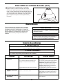
1. GARANTÍA LIMITADA DE POR VIDA DEL MOTOR: si se produce una falla en alguna de las partes del motor de su ventilador debido
a un defecto en los materiales o en la fabricación durante el tiempo de vida del comprador original, Fanimation proporcionará la pieza de
repuesto sin cargo una vez que se devuelva el ventilador defectuoso a nuestro centro de servicios nacional. Se requiere comprobante de
venta. El cliente se hará responsable de todos los gastos de remoción o reinstalación y envío del producto para reparaciones o sustitución.
2. GARANTÍA DE MANO DE OBRA DEL MOTOR POR UN AÑO: si el motor de su ventilador falla antes de cumplirse un año a partir del
momento de su compra original debido a defectos en los materiales o en la fabricación, se efectuará la reparación del mismo sin cargo en
nuestro centro de servicios nacional. El comprador se hará responsable de los gastos de mano de obra luego del período de un año. El
cliente se hará responsable de todos los gastos de remoción o reinstalación y envío del producto para reparaciones o sustitución.
3. Si otra pieza del ventilador fallara dentro del período de un año a partir de la fecha de compra original debido a un defecto en los
materiales o en la fabricación, repararemos o sustituiremos, según creamos conveniente, la pieza defectuosa sin cargo alguno en
nuestro centro de servicios nacional. 4. Debido a las diversas condiciones climáticas, esta garantía no cubre cambios en el acabado,
incluidos oxidación, corrosión, falta de brillo o peladuras.
4. Debido a las diversas condiciones climáticas, esta garantía no cubre cambios en el acabado, incluidos oxidación, corrosión, falta
de brillo o peladuras.
5. Esta garantía es nula y no se aplica a daños por instalación incorrecta, negligencia, accidentes, uso indebido, exposición al calor o
a la humedad en exceso, o como resultado de cualquier modificación realizada al producto original.
6. Todos los gastos de remoción y reinstalación del ventilador son responsabilidad exclusiva del propietario, y no de la tienda que
vendió el ventilador o de Fanimation.
7. Fanimation se reserva el derecho de modificar o discontinuar un producto en cualquier momento, o sustituir cualquier pieza según
lo establecido por esta garantía.
8. Bajo ninguna circunstancia se podrá devolver un ventilador sin previa autorización por parte de Fanimation. Las devoluciones
autorizadas deberán ir acompañadas del recibo de venta y deberán enviarse a Fanimation, previo pago del flete. El ventilador que se
devuelve deberá estar embalado en forma adecuada a fin de evitar daños durante su transporte. Fanimation no se hará responsable
de los daños que resulten del mal empaquetamiento del producto.
9. Se entiende que las reparaciones y las sustituciones son el único recurso disponible de Fanimation. No existe ninguna garantía
expresa o implícita. Por la presente, Fanimation niega todas las garantías implícitas, que incluyen, entre otras, la comerciabilidad y la
aptitud para determinado fin hasta donde la ley lo permita. Algunos estados no permiten limitaciones sobre las garantías implícitas.
Fanimation no se hará responsable por daños accidentales, resultantes o especiales derivados del uso o el rendimiento del producto o
en conjunción con éste, excepto en los casos en los que la ley así lo disponga. Esta garantía le otorga derechos legales especiales y
es posible que también goce de otros derechos que pueden variar según el estado.
GARANTÍA LIMITADA DE POR VIDA
Se extiende al comprador original de un Ventilador Fanimation.
Índice
Instrucciones para el desempaque . . . . . . . . . . . . . . . . . . . . . . . . . . . .19
Requisitos eléctricos y estructurales..................... . . . . . . 20
Uso eficiente de la energía en ventiladores de techo . . . . . . . . . . . . . .20
Cómo ensamblar el ventilador de techo .................. . . . . . . 22
Cómo colgar el ventilador de techo . . . . . . . . . . . . . . . . . . . . . . . . . . . .23
25
Cómo realizar la instalación eléctrica del ventilador de techo. . . . . . .
Cómo utilizar su ventilador de techo
Instalación de la cubierta del capuchón .................. . . . . . . 26
.............. . . . . . . . . . . . . . . .
Solución de problemas . . . . . . . . . . . . . . . . . . . . . . . . . . . . . . . . . . . . . . . .
Mantenimiento
............. . . . . . . . . . . . . . . . . . . . . . . . . . . . . . . . . . .
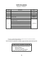
Lista de piezas . . . . . . . . ....... . . . . . . . . . . . . . . . . . . . . . . . . . . . . . . . .
Ilustración del despiece . . . . . . . . . . . . . . . . . . . . . . . . . . . . . . . . . . . . . . .
26
27
27
28
29
10. Es normal que se produzca un cierto movimiento oscilante y esto no debe considerarse un problema o defecto.

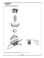
Verifique que haya recibido las siguientes piezas:
• Unidad del motor
• Barral
• Capuchón
• Unidad del soporte de suspensión
• Cubierta de unión del motor
• Control de pared
• Bolsa de accesorios:
– Cuatro conectores de cables
– Llave de 7/16˝
– Tornillo de cabeza cuadrada de 3/8˝ x 5˝ con
arandela plana
– Destornillador Phillips de 1½˝
• Bolsa con cable de soporte:
– Cable de soporte para techo
– Abrazadera de cables
– Tornillo de cabeza cuadrada de 3/8˝ x 2˝
– Arandela plana de 3/8˝
ADVERTENCIA
No instale ni utilice el ventilador si falta alguna pieza o si
hay piezas dañadas. Este producto está diseñado para ser
utilizado sólo con las piezas suministradas o los accesorios
indicados por Fanimation específicamente para el mismo. La
sustitución de piezas o accesorios que Fanimation no designó
para usar con este producto podría ocasionar lesiones
personales o daños en el ventilador. Póngase e
n contacto
con su tienda si faltan piezas o hay piezas dañadas.
Instrucciones para el desempaque
Para su comodidad, marque cada uno de los pasos. A medida que completa cada paso, coloque una marca de verificación.
Con esto se asegurará de completar todos los pasos y podrá saber desde dónde retomar si fuera interrumpido.
NOTA: si no está seguro de la descripción de una
pieza, consulte la ilustración del despiece.
Este manual está diseñado para facilitar, en la medida de lo posible, el ensamblaje,
la instalación, el funcionamiento y el mantenimiento de su ventilador de techo
La caja de distribución eléctrica y los conectores de la caja
deben ser del tipo requerido por el código local. El cable más
pequeño debe ser un cable de tres conductores (de dos
conductores con conexión a tierra) del siguiente tamaño:
Herramientas necesarias para el ensamblaje
Materiales
longitud del cable instalado tamaño del cable según el A.W.G.
(Calibre de Alambre Estadounidense)
14
12
hasta 15,2 m (50 pies)
de 15,2 a 30,5 m (50 a 100 pies)
• Destornillador Phillips
• Escalera de tijera
• Destornillador de ¼˝
• Pelacables
• Cuatro conectores de
cables (incluidos)
NOTA: coloque las piezas de las bolsas de piezas individuales
en un contenedor pequeño para evitar que se extravíen. Si faltan
piezas, póngase en contacto con su proveedor local.
▲ADVERTENCIA
Antes de ensamblar el ventilador de techo, consulte la
sección sobre el método correcto de instalación eléctrica del
ventilador (página 25). Si siente que no posee la experiencia
o los conocimientos eléctricos necesarios, contrate a un
electricista autorizado para instalar el ventilador.
19
Barral
Unidad del soporte
de suspensión
Unidad del motor
Bolsa de accesorios
Control de pared
Capuchón
Cubierta de unión
del motor
AVERTISSEMENT
N'installez pas et n'utilisez pas le ventilateur si l'une de
ses pièces est endommagée ou manquante. Ce produit
est conçu pour utiliser uniquement les pièces l'accom-
pag-nant et/ou les accessoires spécifiquement conçus
pour ce produit par Fanimation. La substitution de
pièces ou d'accessoires non conçus par Fanimation
pour être utilisés avec ce produit peut provoquer des
bless-ures ou des dommages matériels. Contactez
votre lieu de vente en cas de pièces manquantes ou
endommagées.
Reportez-vous à la section sur la méthode appropriée
de câblage du ventilateur (page 25) avant d'assembler
votre ventilateur de plafond. Faites installer votre
ventilateur par un électricien agréé si vous pensez que
vous n'avez pas assez de connaissances ou d'expérience
en câblage.
AVERTISSEMENT

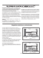
Requisitos eléctricos y estructurales
Su nuevo ventilador de techo requiere una línea de
suministro eléctrico con conexión a tierra de 120 voltios de
CA, 60 Hz, circuito de 15 amperios. La normativa eléctrica
requiere el uso de una caja de distribución eléctrica para
ventiladores que soporte el peso extra y el movimiento
asociado a un ventilador de techo. La caja de distribución
eléctrica será etiquetada como tal y soportará un ventilador
de techo de un peso de hasta 70 libras. Dichas cajas varían
en tipos y diseños. Asegúrese d que el tipo de su caja reúne
los criterios para el ventilador que se está instalando. Las
ilustraciones 1, 2 y 3 muestran las diferentes configuraciones
estructurales que pueden ser utilizadas para dicha caja de
distribución eléctrica.
Uso de perfil bajo (Figura 1)
La caja lisa de 1/2 pulgada de profundidad será atornillada a
una viga o bloque. Se utilizará si solo un cable va a ser
introducido en la caja. También está disponible en una
configuración de montaje endosado.
2" x 4"
Figura 1
Figura 2
2" x 4"
Uso de perfil profundo (Figura 2)
La caja de 2-1/4 pulgada será atornillada a un bloque entre
vigas que tenga suficiente espacio para colocar más de un
cable.
r v r cho
El nivel de rendimiento y ahorro de energía de los
ventiladoresdetechodependendesucorrectainstalación
yuso.Acontinuaciónlepresentamosalgunassugerencias
para asegurar un rendimiento eficiente del producto.
Apague el ventilador cuando no se encuentre en la
habitación
Los ventiladores son para refrescar a la gente, no a
las habitaciones. Si la habitación está vacía, apague el
ventilador de techo para ahorrar energía.
Uso del ventilador de techo todo el año
En verano: Use el ventilador de techo en sentido contrario a
las agujas del reloj. El flujo de aire que produce el ventilador
crearáunefectofríodelaireque lorefrescarámás.Seleccio
ne
una velocidad que le proporcione una brisa confortable. Las
velocidades más bajas consumen menos energía.
En invierno: Invierta el motor y haga funcionar el ventilador
de techo a velocidad baja y en el sentido de las agujas
del reloj. Esto produce una suave corriente ascendente,
que obliga al aire cálido que se acumula cerca del techo a
bajar al espacio ocupado. No olvide ajustar el termostato
cuando utilice el ventilador de techo. Con este sencillo
paso puede ahorrar energía adicional y dinero.
Techo
Techo
Vigas del
techo
Vigas del
techo
Caja de distribución
eléctrica
Caja de distribución
eléctrica
20
Selección del lugar de montaje adecuado
Los ventiladores de techo se deben instalar en el centro
de la habitación, a 2,13 m (7 pies) de altura del piso hasta
la cuchilla como mínimo y 0,5m (18 pulgadas) de las
paredes hasta la cuchilla. Si la altura del techo lo permite,
instale el ventilador a 2,5m (8-9 pies) de altura del piso
hasta la cuchilla para un flujo de aire óptimo. Consulte en
su tienda minorista de Fanimation para obtener accesorios
de montaje opcionales.
La page est en cours de chargement...
La page est en cours de chargement...
La page est en cours de chargement...
La page est en cours de chargement...
La page est en cours de chargement...
La page est en cours de chargement...
La page est en cours de chargement...
La page est en cours de chargement...
La page est en cours de chargement...
La page est en cours de chargement...
-
 1
1
-
 2
2
-
 3
3
-
 4
4
-
 5
5
-
 6
6
-
 7
7
-
 8
8
-
 9
9
-
 10
10
-
 11
11
-
 12
12
-
 13
13
-
 14
14
-
 15
15
-
 16
16
-
 17
17
-
 18
18
-
 19
19
-
 20
20
-
 21
21
-
 22
22
-
 23
23
-
 24
24
-
 25
25
-
 26
26
-
 27
27
-
 28
28
-
 29
29
-
 30
30


Fanimation FP8018BL Le manuel du propriétaire
- Catégorie
- Ventilateurs ménagers
- Taper
- Le manuel du propriétaire
dans d''autres langues
Documents connexes
-
Fanimation FP7964BOB Le manuel du propriétaire
-
-
-
-
Fanimation FP8003BPN Le manuel du propriétaire
-
-