DirekTronik 20117055 Le manuel du propriétaire
- Taper
- Le manuel du propriétaire

Browan Communications Inc.
No.15-1, Zhonghua Rd.,
Hsinchu Industrial Park,
Hukou, Hsinchu,
Taiwan, R.O.C. 30352
Tel: +886-3-6006899
Fax: +886-3-5972970
1
Pico Next Gateway
User Guide
Document Number
BQW_02_0031.007

Browan Communications Inc.
No.15-1, Zhonghua Rd.,
Hsinchu Industrial Park,
Hukou, Hsinchu,
Taiwan, R.O.C. 30352
Tel: +886-3-6006899
Fax: +886-3-5972970
2
Revision History
Revision
Date
Description
.001
Aug. 19, 2021
Browan first release
.002
Feb. 15, 2022
Add Regulatory and change LED function
.003
Apr. 28, 2022
Add WiFi Station configuration
.004
Aug. 5, 2022
Add Packet Forwarder Whitelist Filter, OpenVPN Client
configuration, and Professional Installation instructions
.005
Oct. 6, 2022
Add firmware upgrade details. Update Whitelist Filter
and Channel Scan
.006
Oct. 31, 2022
Add passive PoE data
.007
Jan. 13, 2023
Add Auto OTA update, file export, PLMN ID for LTE, and
packet forwarder restore to default

Browan Communications Inc.
No.15-1, Zhonghua Rd.,
Hsinchu Industrial Park,
Hukou, Hsinchu,
Taiwan, R.O.C. 30352
Tel: +886-3-6006899
Fax: +886-3-5972970
3
Copyright
© 2023 BROWAN COMMUNICATIONS INC.
This document is copyrighted with all rights reserved. No part of this publication may be reproduced,
transmitted, transcribed, stored in a retrieval system, or translated into any language in any form by any
means without the written permission of BROWAN COMMUNICATIONS INC.
Notice
BROWAN COMMUNICATIONS INC. reserves the right to change specifications without prior notice.
While this manual has been compiled with great care, it may not be deemed as an assurance of product
characteristics. BROWAN COMMUNICATIONS INC. shall be liable only to the degree specified in the terms
of sale and delivery.
The reproduction and distribution of the documentation and software supplied with this product and the
use of its contents are subject to written authorization from BROWAN COMMUNICATIONS INC.
Trademark
The product described in this document is a licensed product of BROWAN COMMUNICATIONS INC.

Browan Communications Inc.
No.15-1, Zhonghua Rd.,
Hsinchu Industrial Park,
Hukou, Hsinchu,
Taiwan, R.O.C. 30352
Tel: +886-3-6006899
Fax: +886-3-5972970
4
Regulatory
Federal Communication Commission Statement (FCC, U.S.)
This equipment has been tested and found to comply with the limits for a Class B digital device,
pursuant to Part 15 of the FCC Rules. These limits are designed to provide reasonable protection
against harmful interference in a residential installation. This equipment generates, uses and can
radiate radio frequency energy and, if not installed and used in accordance with the instructions, may
cause harmful interference to radio communications. However, there is no guarantee that
interference will not occur in an installation. If this equipment does cause harmful interference to radio
or television reception, which can be determined by turning the equipment off and on, the user is
encouraged to try to correct the interference by one of the following measures:
• Reorient or relocate the receiving antenna.
• Increase the separation between the equipment and receiver.
• Connect the equipment into an outlet on a circuit different from that to which the receiver is
connected.
• Consult the dealer or an experienced radio/TV technician for help.
This device complies with Part 15 of the FCC Rules. Operation is subject to the following two
conditions:
(1) This device may not cause harmful interference, and
(2) this device must accept any
interference received, including interference that may cause
undesired operation.
Radiation Exposure Statement
This device complies with RF radiation exposure limits set forth for an uncontrolled environment. This transmitter
must not be co-located or operating in conjunction with any other antenna or transmitter.
This device must operate with a minimum distance of 20 cm between the radiator and user body.
FCC Caution:
Any changes or modifications not expressly approved by the party responsible for compliance could
void the user's authority to operate this equipment

Browan Communications Inc.
No.15-1, Zhonghua Rd.,
Hsinchu Industrial Park,
Hukou, Hsinchu,
Taiwan, R.O.C. 30352
Tel: +886-3-6006899
Fax: +886-3-5972970
5
IC WARNING
This device contains license-exempt transmitter(s)/receiver(s) that comply with Innovation, Science
and Economic Development Canada’s license-exempt RSS(s). Operation is subject to the following two
conditions:
1. This device may not cause interference.
2. This device must accept any interference, including interference that may cause undesired
operation of the device
L’émetteur/récepteur exempt de licence contenu dans le présent appareil est conforme aux CNR
d’Innovation, Sciences et Développement économique Canada applicables aux appareils radio exempts
de licence. L’exploitation est autorisée aux deux conditions suivantes :
1. L’appareil ne doit pas produire de brouillage;
2. L’appareil doit accepter tout brouillage radioélectrique subi, même si le brouillage est susceptible
d’en compromettre le fonctionnement.
Radiation Exposure Statement:
This equipment complies with Canada radiation exposure limits set forth for an uncontrolled environment. This
equipment should be installed and operated with minimum distance 20cm between the radiator & your body.
Déclaration d'exposition aux radiations:
Cet équipement est conforme Canada limites d'exposition aux radiations dans un environnement non
contrôlé. Cet équipement doit être installé et utilisé à distance minimum de 20cm entre le radiateur et
votre corp.

Browan Communications Inc.
No.15-1, Zhonghua Rd.,
Hsinchu Industrial Park,
Hukou, Hsinchu,
Taiwan, R.O.C. 30352
Tel: +886-3-6006899
Fax: +886-3-5972970
6
Professional Installation Instructions
1. Installation personal
This product is designed for specific applications and needs to be installed by a
qualified person who has RF and related rules knowledge. The general user shall
not attempt to install or change the settings.
2. Installation location
The product shall be installed at a location where the radiating antenna can be kept
20 cm from nearby persons in normal operation conditions to meet regulatory RF
exposure requirements.
3. External antenna
Use only the antennas that have been approved by the applicant. Non-approved
antenna(s) may produce unwanted spurious or excessive RF transmitting power,
which may lead to the violation of FCC/IC limits and is prohibited.
4. Installation procedure
Please refer to user's manual for details.
5. Warning
Please carefully select the installation position and make sure that the final output
power does not exceed the limits set forth in relevant rules. Violation of the rules
could lead to serious federal penalties.

Browan Communications Inc.
No.15-1, Zhonghua Rd.,
Hsinchu Industrial Park,
Hukou, Hsinchu,
Taiwan, R.O.C. 30352
Tel: +886-3-6006899
Fax: +886-3-5972970
7
Instructions d'installation professionnelle
1. Installation
Ce produit est destine a un usage specifique et doit etre installe par un personnel
qualifie maitrisant les radiofrequences et les regles s'y rapportant. L'installation et
les reglages ne doivent pas etre modifies par l'utilisateur final.
2. Emplacement d'installation
En usage normal, afin de respecter les exigences reglementaires concernant
l'exposition aux radiofrequences, ce produit doit etre installe de facon a respecter
une distance de 20 cm entre l'antenne emettrice et les personnes.
3. Antenn externe.
Utiliser uniiquement les antennes approuvees par le fabricant. L'utilisation d'autres
antennes peut conduire a un niveau de rayonnement essentiel ou non essentiel
depassant les niveaux limites definis par FCC/IC, ce qui est interdit.
4. Procedure d'installation
Consulter le manuel d'utilisation.
5. Avertissement
Choisir avec soin la position d'installation et s'assurer que la puissance de sortie ne
depasse pas les limites en vigueur. La violation de cette regle peut conduire a de
serieuses penalites federales.

Browan Communications Inc.
No.15-1, Zhonghua Rd.,
Hsinchu Industrial Park,
Hukou, Hsinchu,
Taiwan, R.O.C. 30352
Tel: +886-3-6006899
Fax: +886-3-5972970
8
Table of Contents
Table of Contents
REVISION HISTORY ...................................................................................................................................................... 2
COPYRIGHT ................................................................................................................................................................. 3
NOTICE. ...................................................................................................................................................................... 3
TRADEMARK ............................................................................................................................................................... 3
REGULATORY .............................................................................................................................................................. 4
PROFESSIONAL INSTALLATION INSTRUCTIONS ........................................................................................................... 6
1 PRODUCT OVERVIEW ................................................................................................................................... 10
1.1 PRODUCT FEATURES ..................................................................................................................................... 10
1.2 LED FUNCTIONS ............................................................................................................................................ 10
1.3 RESET BUTTON ............................................................................................................................................. 10
1.4 I/O PORTS ..................................................................................................................................................... 11
1.5 ACCESSORIES ................................................................................................................................................ 12
2 INSTALLATION .............................................................................................................................................. 12
2.1 POWER UP .................................................................................................................................................... 12
2.1.1 DC Adapter .............................................................................................................................................. 12
2.1.2 Terminal Block ......................................................................................................................................... 12
2.1.3 Ethernet ................................................................................................................................................... 12
2.1.3.1 Passive PoE........................................................................................................................................ 13
2.2 UPGRADE FIRMWARE ................................................................................................................................... 14
3 GUI ACCESS ................................................................................................................................................... 14
3.1 OPEN ADMIN GUI ......................................................................................................................................... 14
4 SYSTEM......................................................................................................................................................... 15
4.1 ADMINISTRATION ......................................................................................................................................... 15
4.2 RESTORE ....................................................................................................................................................... 16
4.3 SYSTEM FIRMWARE ...................................................................................................................................... 16
4.4 SUPPORT ...................................................................................................................................................... 17
5 LORA SETTINGS ............................................................................................................................................. 17
5.1 MODE SELECTION ......................................................................................................................................... 17
5.1.1 Packet Forwarder .................................................................................................................................... 17
5.1.1.1 Gateway Info ..................................................................................................................................... 19
5.1.1.2 Antenna Gain .................................................................................................................................... 19
5.1.1.3 Radio and Channel Settings .............................................................................................................. 20
5.1.1.4 LBT Settings ....................................................................................................................................... 21

Browan Communications Inc.
No.15-1, Zhonghua Rd.,
Hsinchu Industrial Park,
Hukou, Hsinchu,
Taiwan, R.O.C. 30352
Tel: +886-3-6006899
Fax: +886-3-5972970
9
5.1.2 Whitelist Filter ......................................................................................................................................... 21
5.1.2.1 Examples of Whitelist Filter .............................................................................................................. 22
5.1.3 Config Restore ......................................................................................................................................... 24
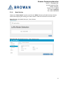
5.1.4 Basic Station ............................................................................................................................................ 25
5.1.4.1 Radio Info .......................................................................................................................................... 26
5.1.4.2 Connection Configuration ................................................................................................................. 26
5.2 CHANNEL SCAN............................................................................................................................................. 28
5.3 LOG............................................................................................................................................................... 29
6 NETWORK ..................................................................................................................................................... 29
6.1 WAN ............................................................................................................................................................. 29
6.1.1 WAN Status ............................................................................................................................................. 30
6.1.2 WAN Settings .......................................................................................................................................... 31
6.1.2.1 Ethernet WAN ................................................................................................................................... 31
6.1.2.2 Wireless Station ................................................................................................................................ 32
6.1.2.3 3G/4G LTE ......................................................................................................................................... 33
6.1.2.4 Dual WAN (Ethernet+3G/4G) ............................................................................................................ 33
6.1.2.5 Dual WAN (Ethernet+WiFi) ............................................................................................................... 34
6.1.3 3G/4G LTE Log ......................................................................................................................................... 35
6.2 VPN .............................................................................................................................................................. 36
6.2.1 VPN Settings ............................................................................................................................................ 36
6.2.2 VPN Log ................................................................................................................................................... 38
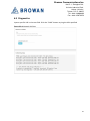
6.3 DIAGNOSTICS ............................................................................................................................................... 39

Browan Communications Inc.
No.15-1, Zhonghua Rd.,
Hsinchu Industrial Park,
Hukou, Hsinchu,
Taiwan, R.O.C. 30352
Tel: +886-3-6006899
Fax: +886-3-5972970
10
1 Product Overview
1.1 Product Features
The Pico Next Gateway is a LoRa gateway with GPS, using numerous ways of connection:
ethernet, LTE, and Wi-Fi. Depending upon the SKU, some functions might not be available.
Pico Next is specifically designed for wide-area IoT applications. Applications include, but are
not limited to, home security, automatic meter-reading, monitoring fault-indicators, and
monitoring streetlights. This gateway is very suitable for small businesses or private area uses
like at parking lots, exhibition centers, and campuses.
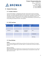
1.2 LED Functions
LED Functions
Constant
Flashing
Off
Power
Power On
Booting /OTA
OFF
Internet
Internet
Available
Checking
Internet
RFU
Service
LNS Connected
RFU
LNS Not
Connected
LoRa
LoRa Working
Initializing
LoRa Not
Working
1.3 Reset Button
Reboot:
By pressing and holding the RESET Button, the Power LED will start flashing. The “reboot”
procedure will be triggered when the RESET Button is released while the Power LED light is
flashing.
Restore to Default:
By pressing and holding the RESET Button, the Power LED will start flashing. The “restore to
default” procedure will be triggered when the RESET Button released after the Power LED
light becomes constant.

Browan Communications Inc.
No.15-1, Zhonghua Rd.,
Hsinchu Industrial Park,
Hukou, Hsinchu,
Taiwan, R.O.C. 30352
Tel: +886-3-6006899
Fax: +886-3-5972970
11
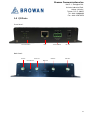
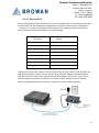
1.4 I/O Ports
Front Panel -
Back Panel -
Functional LEDs
RJ45
Terminal Block
DC Jack
LTE Ant.
Wi-Fi Ant.
GPS Ant.
LoRa Ant.
Reset Button
SIM Card

Browan Communications Inc.
No.15-1, Zhonghua Rd.,
Hsinchu Industrial Park,
Hukou, Hsinchu,
Taiwan, R.O.C. 30352
Tel: +886-3-6006899
Fax: +886-3-5972970
12
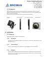
1.5 Accessories
Different SKUs would provide accessories pertaining to that country or SKU, such as the
adapter plug model and GPS antenna. LTE and Wireless antennas are interchangeable; they
have the same specifications.
*Please note that the GPS antenna needs to be purchased separately. *
Adapter LoRa Antenna LTE and Wi-Fi Antenna GPS Antenna *
2 Installation
2.1 Power up
Power up Pico Next through the following ways.
2.1.1 DC Adapter
Connect the power adapter provided to the DC jack In. Pico Next will automatically turn on
after powering up.
2.1.2 Terminal Block
Connect a power supply to Pico Next with a 3-pin pluggable male terminal block.
2.1.3 Ethernet
Connect a RJ45 Ethernet cable to Power-over-Ethernet in (WAN port). Connect the other
end of the ethernet cable to a passive PoE that ensures a power of 12V / 1.5A DC. Provide
power to the passive PoE.

Browan Communications Inc.
No.15-1, Zhonghua Rd.,
Hsinchu Industrial Park,
Hukou, Hsinchu,
Taiwan, R.O.C. 30352
Tel: +886-3-6006899
Fax: +886-3-5972970
13
2.1.3.1 Passive PoE
Passive PoE, passive Power over Ethernet, is a non-standard PoE. It can deliver power over
the Ethernet lines, but without the negotiation or communication process; the power is
“always-on”. It requires using passive PoE injectors for networks, which send electric
current out over the Ethernet cable at a certain voltage.
Pins at RJ45
Connector
Passive PoE (DC on
Spares)
Pin 1
Rx+
Pin 2
Rx-
Pin 3
Tx+
Pin 4
DC +9V~+30V
Pin 5
DC +9V~+30V
Pin 6
Tx-
Pin 7
Ground
Pin 8
Ground
In general, a Passive PoE Injector has three connectors: DC jack, RJ45 for PoE and RJ45 for
LAN. Simply connect a power source (output range of power adapter must be between
10V~30V) to the DC jack on the injector and the LED indicator will turn on. Then, use an
ethernet cable to connect the LAN port on injector to your network, and use another
ethernet cable to connect the PoE port on injector to your PicoNext Gateway.

Browan Communications Inc.
No.15-1, Zhonghua Rd.,
Hsinchu Industrial Park,
Hukou, Hsinchu,
Taiwan, R.O.C. 30352
Tel: +886-3-6006899
Fax: +886-3-5972970
14
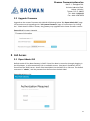
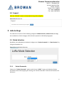
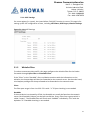
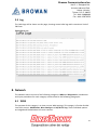
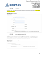
2.2 Upgrade Firmware
Upgrade to the newest firmware with Web GUI following below “3.1 Open Admin GUI” page
13 instructions and upgrading with “4.3 System Firmware” page 15 instructions. By clicking
the " Check New Firmware” button, the gateway may upgrade to the latest firmware version.
Figure 2.2-A Firmware Upgrade
3 GUI Access
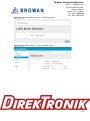
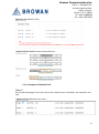
3.1 Open Admin GUI
Default mode of Pico Next Gateway is DHCP. Once Pico Next is turned on through plugging in
the DC adapter, it will automatically link to available servers. Pico Next’s IP address can be
found from the DHCP server. Access Pico Next WebUI via the DHCP IP on Chrome. The default
username is “admin”, and the password can be found on the back label.
Figure 3.1-A Admin GUI

Browan Communications Inc.
No.15-1, Zhonghua Rd.,
Hsinchu Industrial Park,
Hukou, Hsinchu,
Taiwan, R.O.C. 30352
Tel: +886-3-6006899
Fax: +886-3-5972970
15
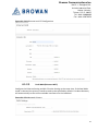
Figure 3.1-B Admin GUI
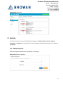
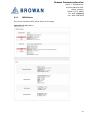
4 System
The System menu consists of the following categories: Administration, Restore, System
Firmware and Support. An introduction of each category will be distinctly stated in individual
paragraphs.
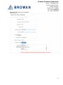
4.1 Administration
Pico Next login password can be configured on this page.
Figure 4.1-A Router Password

Browan Communications Inc.
No.15-1, Zhonghua Rd.,
Hsinchu Industrial Park,
Hukou, Hsinchu,
Taiwan, R.O.C. 30352
Tel: +886-3-6006899
Fax: +886-3-5972970
16
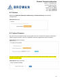
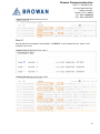
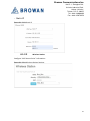
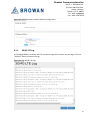
4.2 Restore
Restore the Password Credential, LoRa Setting and Network Setting to the default
configurations.
Figure 4.2-A Restore
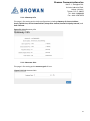
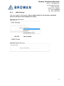
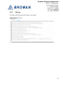
4.3 System Firmware
Here the current firmware version can be found. Click the "Choose File" button to upload the
newest system firmware. Click the "UPGRADE" button to upgrade the system firmware.
Figure 4.3-A System Firmware
The Auto Firmware Update can be enabled, and the device will check the OTA server for new
firmware versions daily.
Figure 4.3-B System Firmware

Browan Communications Inc.
No.15-1, Zhonghua Rd.,
Hsinchu Industrial Park,
Hukou, Hsinchu,
Taiwan, R.O.C. 30352
Tel: +886-3-6006899
Fax: +886-3-5972970
17
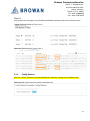
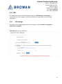
4.4 Support
Click the “EXPORT” button to download the log and config files.
Figure 4.4-A Export Log
5 LoRa Settings
The LoRa menu consists of the following categories: Mode Selection, Channel Scan and Log.
An introduction of each category will be distinctly stated in individual paragraphs.
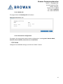
5.1 Mode Selection
By default, the LoRa Mode is disabled. Configure the "Packet Forwarder" or "Basic Station" by
using the dropdown list.
Figure 5.1-A LoRa Mode Selection
5.1.1 Packet Forwarder
Choose the "Packet Forwarder" option and click the "APPLY" button to Enable the Packet
Forwarder mode. After applying the setting, the "Packet Forwarder" field can be found on the
left menu.

Browan Communications Inc.
No.15-1, Zhonghua Rd.,
Hsinchu Industrial Park,
Hukou, Hsinchu,
Taiwan, R.O.C. 30352
Tel: +886-3-6006899
Fax: +886-3-5972970
18
Figure 5.1.1-A LoRa Mode Selection - Packet Forwarder
Figure 5.1.1-B LoRa Settings - Packet Forwarder menu

Browan Communications Inc.
No.15-1, Zhonghua Rd.,
Hsinchu Industrial Park,
Hukou, Hsinchu,
Taiwan, R.O.C. 30352
Tel: +886-3-6006899
Fax: +886-3-5972970
19
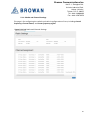
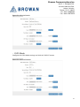
5.1.1.1 Gateway Info
This page is for setting up the LoRa configuration including Gateway ID, Server Address,
Server Uplink Port, Server Downlink Port, Keep-Alive Interval, Statistics Display Interval, and
Push Timeout.
Figure 5.1.1.1-A Gateway Info
5.1.1.2 Antenna Gain
This page is for setting up the antenna gain of Lora.
Figure 5.1.1.2-A Antenna Gain

Browan Communications Inc.
No.15-1, Zhonghua Rd.,
Hsinchu Industrial Park,
Hukou, Hsinchu,
Taiwan, R.O.C. 30352
Tel: +886-3-6006899
Fax: +886-3-5972970
20
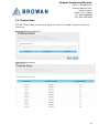
5.1.1.3 Radio and Channel Settings
This page is for configuring the radio 0 and radio 1 configurations of Lora, including Central
Frequency, Channel Status, and Center frequency offset.
Figure 5.1.1.3-A Radio and Channel Settings
La page est en cours de chargement...
La page est en cours de chargement...
La page est en cours de chargement...
La page est en cours de chargement...
La page est en cours de chargement...
La page est en cours de chargement...
La page est en cours de chargement...
La page est en cours de chargement...
La page est en cours de chargement...
La page est en cours de chargement...
La page est en cours de chargement...
La page est en cours de chargement...
La page est en cours de chargement...
La page est en cours de chargement...
La page est en cours de chargement...
La page est en cours de chargement...
La page est en cours de chargement...
La page est en cours de chargement...
La page est en cours de chargement...
-
 1
1
-
 2
2
-
 3
3
-
 4
4
-
 5
5
-
 6
6
-
 7
7
-
 8
8
-
 9
9
-
 10
10
-
 11
11
-
 12
12
-
 13
13
-
 14
14
-
 15
15
-
 16
16
-
 17
17
-
 18
18
-
 19
19
-
 20
20
-
 21
21
-
 22
22
-
 23
23
-
 24
24
-
 25
25
-
 26
26
-
 27
27
-
 28
28
-
 29
29
-
 30
30
-
 31
31
-
 32
32
-
 33
33
-
 34
34
-
 35
35
-
 36
36
-
 37
37
-
 38
38
-
 39
39


DirekTronik 20117055 Le manuel du propriétaire
- Taper
- Le manuel du propriétaire
dans d''autres langues
- English: DirekTronik 20117055 Owner's manual
Autres documents
-
 Browan WLRGFM-100 Manuel utilisateur
-
Browan S1 Manuel utilisateur
-
SMC Networks SMCGS501P Manuel utilisateur
-
Accton Technology RPU150W Quick Installation Manual
-
 HON HAI PRECISION IND. MCLT60198 Manuel utilisateur
-
-
SMC Networks SMCGS26C-Smart Manuel utilisateur
-
ZyXEL AMG1312-T10B Guide de démarrage rapide
-
-
 ZyXEL Communications NWA-8500 Manuel utilisateur


