
start here commencez ici
empezar aquí
Assembly Instructions
Item No: FR
47756
Les Instructions D’assemblage
Numéro d’article: FR
47756
Instrucciones De Montaje
Número del artículo: FR46406
English Spanish French
S
C
W
L
(c)
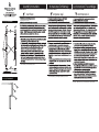
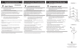
2. Unpack fixture from carton
Drawing 5- Panel install
2
1
1
g-4
4
Drawing 4- Stem install
Note: use knobs (1) to secure panels (2) to fixture
Nota: use las perillas (1) para asegurar los paneles (2) al accesorio
Remarque : utilisez les boutons (1) pour fixer les panneaux (2) au luminaire

ereh trats ici zecnemmoc
íuqa razepme
snoitcurtsnI gnitnuoM
Instrucciones de montaje
Instrucciones de montaje
.krow nac uoy hcihw ni aera raelc a dniF .1 .r T .1 .r
DRAWING 2 - MOUNTING
DRAWING 3 - MOUNTING
A1
J
1
DRAWING 1 - CANOPY ASSEMBLY
English Spanish French
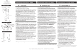
1. If the stems of the fixture have not be attached to the main body.
Please do so at this time.
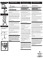
2. Attached the loops on the canopy (C) to the loops on the top of the
stems (L). This is accomplished by opening the chain link (CL) provided
and slipping it through the loops, and then closing it - see DRAWING 1.
3. Now slip the wires (W) from the stem through the center hole of the
loop in the canopy. NOTE: the fixture is supplied with a piece of black
sleeving (S). After the wires are slipped through the loops, slide the
black sleeving (S) over the black and red wires and through the loops
to cover them.
4. Fixture is ready to installation.
CL
C
L
1. To begin installation first remove the mounting plate (1) from the
canopy (C). This is accomplished by removed screws in canopy (H)
2. Now take mounting plate (1) and attach it to the junction box (J) using
two 8-32 screws NOT PROVIDED.
3. Now with assistance take the assembled fixture and lift it up to the
ceiling and using the hook on the end of inspection cable, attached to
the inside of canopy (C), hook it into the mounting plate (1). Now slowly
release the fixture until it is safely hanging from the inspection cable -
see DETAIL 1. NOTE: It is still recommend that an assistant be used to
support fixture during this process.
4. Make all necessary electrical connections following instruction sheet
(Wiring Instructions for 0-10 volt LED dimmer) provided.
5. To mount canopy (C) to ceiling, replace the previously removed
screws (H)
6. Wiring and installation is complete and power can be restored.
SAFETY WARNING: READ WIRING AND GROUNDING INSTRUC-
TIONS (Wiring Instructions for 0-10 volt LED dimmer) AND ANY
ADDITIONAL DIRECTIONS. TURN POWER SUPPLY OFF DURING
INSTALLATION. IF NEW WIRING IS REQUIRED, CONSULT A
QUALIFIED ELECTRICIAN OR LOCAL AUTHORITIES FOR CODE
REQUIREMENTS.
[Detail 1]
1
HOOK INSPECTION
CABLE TO MOUNTING STRAP.
HOOK
J
F
C
1. Si los vástagos de la luminaria no se han unido al cuerpo
principal. Por favor, hazlo, en este momento.
2. Sujete los bucles en la cubierta (C) a los bucles en la parte
superior de los tallos (L). Esto se logra abriendo el eslabón de la
cadena (CL) provisto y deslizándolo a través de los bucles, y
luego cerrándolo - vea DIBUJO 1.
1. Si les tiges du luminaire n’ont pas été attachées au corps
principal. S'il vous plaît faites-le, à ce moment.
2. Fixez les boucles de la canopée (C) aux boucles situées au
sommet des tiges (L). Ceci est accompli en ouvrant le maillon de
chaîne (CL) fourni et en le glissant dans les boucles, puis en le
refermant - voir SCHÉMA 1.
AVERTISSEMENT DE SÉCURITÉ: LISEZ LES INSTRUCTIONS
DE CÂBLAGE ET DE MISE À LA TERRE (I.S. 18) ET TOUTES
LES INSTRUCTIONS SUPPLÉMENTAIRES. COUPEZ L'ALIMEN-
TATION PENDANT L'INSTALLATION. SI UN NOUVEAU CAB-
LAGE EST NÉCESSAIRE, CONSULTER UN ÉLECTRICIEN
QUALIFIÉ OU LES AUTORITÉS LOCALES POUR LES
EXIGENCES DU CODE.
1. Pour commencer l'installation, retirez d'abord la plaque de montage
(1) de l'auvent (C). Ceci est accompli en retirant les vis du pavillon (H).
2. Prenez maintenant la plaque de montage (1) et fixez-la à la boîte de
jonction (J) à l'aide de deux vis 8-32 NON FOURNIES.
3. Maintenant, avec de l'aide, prenez le luminaire assemblé et soulevez-
le jusqu'au plafond et, à l'aide du crochet situé à l'extrémité du câble
d'inspection, fixé à l'intérieur de l'auvent (C), accrochez-le à la plaque de
montage (1). Relâchez maintenant lentement le luminaire jusqu'à ce
qu'il soit suspendu en toute sécurité au câble d'inspection - voir DÉTAIL
1. REMARQUE : Il est toujours recommandé de faire appel à un
assistant pour soutenir le luminaire pendant ce processus.
4. Effectuez toutes les connexions électriques nécessaires en suivant la
feuille d'instructions (Instructions de câblage pour gradateur LED 0-10
volts) fournie.
5. Pour monter l'auvent (C) au plafond, remplacez les vis (H)
précédemment retirées.
6. Le câblage et l’installation sont terminés et le courant peut être rétabli.
ADVERTENCIA DE SEGURIDAD: LEA LAS INSTRUCCIONES
DE CABLEADO Y CONEXIÓN A TIERRA (I.S. 18) Y CUALQUIER
INSTRUCCIONES ADICIONALES. APAGUE LA FUENTE DE
ALIMENTACIÓN DURANTE LA INSTALACIÓN. SI SE REQUI-
ERE NUEVO CABLEADO, CONSULTE A LAS AUTORIDADES
ELECTRICAS O LOCALES CUALIFICADAS PARA REQUISITOS
DE CÓDIGO.
S
W
W
3. Ahora deslice los cables (W) desde el vástago a través del
orificio central del bucle en la cubierta. NOTA: el accesorio se
suministra con un pedazo de negro manga (S). Después de
deslizar los cables a través de los bucles, deslice los manga
negra (S) sobre los cables negro y rojo y por los bucles para
cubrirlos
4. El accesorio está listo para la instalación.
3. Maintenant, glissez les fils (W) de la tige à travers le trou central
de la boucle dans le couvert. NOTE: le luminaire est fourni avec un
morceau de noir gaine (S). Après avoir glissé les fils dans les
boucles, faites glisser le gaine noire (S) sur les fils noir et rouge et
à travers les boucles pour les couvrir.
4. Le luminaire est prêt à être installé.
2. Unpack fixture from carton
H
1. Para comenzar la instalación, primero retire la placa de
montaje (1) de la cubierta (C). Esto se logra quitando los
tornillos en la cubierta (H)
2. Ahora tome la placa de montaje (1) y fíjela a la caja de
conexiones (J) usando dos tornillos 8-32 NO
PROPORCIONADOS.
3. Ahora, con ayuda, tome el dispositivo ensamblado, levántelo
hasta el techo y, usando el gancho en el extremo del cable de
inspección, sujeto al interior de la cubierta (C), engánchelo en
la placa de montaje (1). Ahora suelte lentamente el dispositivo
hasta que cuelgue de forma segura del cable de inspección;
consulte el DETALLE 1. NOTA: Aún así, se recomienda utilizar
un asistente para sostener el dispositivo durante este proceso.
4. Realice todas las conexiones eléctricas necesarias
siguiendo la hoja de instrucciones (Instrucciones de cableado
para atenuador LED de 0 a 10 voltios) proporcionada.
5. Para montar la cubierta (C) en el techo, reemplace los
tornillos (H) que quitó anteriormente.
6. El cableado y la instalación están completos y se puede
restablecer la energía.

start here
commencez ici
empezar aquí
Item No. Numéro d’article: Número del artículo:
English Spanish French
HINKLEY 33000 Pin Oak Parkway, Avon Lake, OH 44012 800.446.5539 / 440.653.5500 hinkley.com
IS-SCC [safety cable installation]
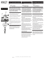
Drawing 1 - Safety Cable Installation
junction
box
3
1
2
ceiling
joist
ADVERTENCIA: PARA EVITAR CHOQUE ELÉCTRICO,
ESTA SECCIÓN DE LA HOJA DE INSTRUCCIONES
ES EL ÚNICO PROPÓSITO DE INSTALACIÓN DEL
CABLE DE SEGURIDAD, Y NO DEBE SER UTILIZADO
PARA REALIZAR LAS CONEXIONES ELÉCTRICAS.
AVERTISSEMENT: POUR ÉVITER UNE ÉLECTROCUTION,
CETTE SECTION DE LA FEUILLE D'INSTRUCTIONS EST
DANS LE SEUL BUT DE CÂBLE DE SÉCURITÉ
INSTALLATION, ET NE DOIT PAS ÊTRE UTILISÉ POUR
FAIRE LES CONNEXIONS ÉLECTRIQUES.
WARNING: TO AVOID ELECTRICAL SHOCK, THIS SECTION
OF THE INSTRUCTION SHEET IS FOR THE SOLE PURPOSE
OF SAFETY CABLE INSTALLATION, AND IS NOT TO BE USED
TO MAKE ANY ELECTRICAL CONNECTIONS.
El cable de seguridad debe estar conectada a una vigueta
de techo u otra estructura permanente independiente de la
caja de conexiones.
1. Utilizando un 3/16 "de diámetro. Taladro, perfore un
agujero piloto (1). Debe ser perforado en la estructura
permanente oa través de la caja de conexiones en el lado
de la vigueta se el cable de seguridad será adjunto
- ver dibujo 1.
2. Inserte y enrosque un tornillo de retraso de 1/4 "de
cabeza hexagonal (2) (no incluido) en el orificio piloto.
3. Continuar la instalación de este aparato de acuerdo con
IS19-50 proporcionado.
4. Después se determina la longitud de cable de seguridad,
deje suficiente cable adicional para que pueda ser
envuelta alrededor de tornillo de tracción. Tema tirafondo
para fijar el cable de seguridad.
. Le câble de sécurité doit être attaché à une solive du
plafond ou une autre structure permanente indépendante de
la boîte de jonction.
1. L'aide d'un foret de 3/16 "de diamètre., Percer un trou
pilote (1). Elle doit être foré dans la structure permanente ou
la boîte de jonction sur le côté solives ont le câble de sécurité
sera ci-joint - voir schéma 1.
2. Insérez et vissez une vis 1/4 "à tête hexagonale de retard
(2) (non inclus) dans le trou pilote.
3. Continuer l'installation de ce luminaire selon IS19-50 fourni.
4. Après longueur de câble de sécurité est déterminé,
prévoyez suffisamment de câble supplémentaire de sorte
qu'il peut être enroulé autour de la vis tire-fond. Sujet
décalage vis pour fixer le câble de sécurité.
The safety cable must be attached to a ceiling joist or other
permanent structure independent of the junction box.
1. using a 3/16" dia. drill, drill a pilot hole (1). It must be drilled into the
permanent structure or through the junction box on the joist side
were the safety cable will be attached - see Drawing 1.
2. Insert and thread a 1/4" hex head lag screw (2) (not included) into
pilot hole.
3. Continue installation of this xture according to IS19-50 provided.
4. After length of safety cable is determined, allow enough extra cable
so it can be wrapped around lag screw. Thread lag screw to secure
safety cable.
..
Make electrical connections from supply wire to fixture lead wires.
Refer to instruction sheet (I.S. 18) and follow all instructions to make
all necessary wiring connections. Then refer back to this sheet to
continue installatio of this fixture.
Haga las conexiones eléctricas del cable de alimentación los
cables conductores del luminario. Consulte la hoja de instrucciones
(IS 18) y siga todas las instrucciones para hacer todas las
conexiones necesarias. Entonces referirse a esta hoja para
continuar instalacion de este luminario.
Effectuer les connexions électriques du câble d'alimentation au
montage des fils conducteurs. Reportez-vous à la feuille d'instruction
(IS 18) et suivez les instructions pour faire toutes les connexions
nécessaires. Ensuite, se reporter à la fiche de continuer installatio
de ce luminaire.
IS-SCC [Instalación de cable de seguridad] IS-SCC [installation de câbles de sécurité]
H
I
N
K
L
E
Y

Wiring
Instructions for 0-10 volt LED dimmer
start here
Instrucciones de cableado para atenuador LED de 0-10 voltios
commencez ici
Instructions de câblage pour gradateur LED 0-10 volts
empezar aquí
J
WIRES FROM
DIMMER
SUPPLY WIRES
FROM
JUNCTION BOX
Your fixture is designed so it can use a standard incandescent
dimmer, Or a 0-10 volt LED dimmer. If a 0-10 volt LED dimmer is
used, it may be necessary to have additonal wiring installed from the
dimmer switch to the fixture. Consulting an electrician will be
necessary.
Su luminaria está diseñada para que pueda usar un atenuador
incandescente estándar o un atenuador LED de 0-10 voltios. Si se utiliza
un atenuador LED de 0-10 voltios, puede ser necesario instalar cableado
adicional desde el interruptor atenuador hasta la luminaria. Consultar a un
electricista será
DIMMER
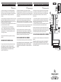
DRAWING 1
SWITCH
D
B
W
G
P
1. If using the optional 0-10 volt dimmer there will be four wires exiting
the junction box. (B) Black [+], (W) White [-], wirng are for the 120 /
277 voltage. The (G) Gray/Pink {-} and (P) Purple {+} are for the 0-10
volt wires from the dimmer (D) - see Drawing 1.
2. The fixture has four wires of corresponding colors. When make the
wire connections follow the chart below.
G
B
WP
1. Si usa el atenuador opcional de 0-10 voltios, habrá cuatro cables
saliendo de la caja de conexiones. (B) Negro [+], (W) Blanco [-], el
cableado es para el voltaje 120/277. El (G) Gris/Rosa {-} y (P) Púrpura
{+} son para los cables de 0-10 voltios del atenuador (D) - vea el Dibujo
1.
2. El accesorio tiene cuatro cables de colores correspondientes. Cuando
realice las conexiones de los cables, siga la tabla a continuación.
Negro (B) de la caja de empalmes (J) conectado a Negro (B) del
accesorio. Blanco (W) de la caja de empalmes (J) cableado a Blanco
(W) del accesorio. Gris/rosa (G) desde la caja de empalmes (J)
cableado a gris/rosa (G) desde la lámpara. Púrpura (P) desde la caja de
empalmes (J) conectado a Púrpura (P) desde el accesorio.
USO INCANDESCENTE DEL DIMMER:
Si usa un atenuador incadescente, siga las instrucciones del fabricante.
NOTA: ASEGÚRESE DE TAPAR EL CABLE GRIS/ROSA Y PÚRPURA
DEL APARATO DENTRO DEL TOLDO. SI NO ESTÁN TAPADOS,
PUEDEN HACER UN CORTOCIRCUITO Y CAUSAR LA FALLA DEL
APARATO
Votre luminaire est conçu pour pouvoir utiliser un variateur à incandes-
cence standard ou un variateur LED 0-10 volts. Si un gradateur LED
0-10 volts est utilisé, il peut être nécessaire d'avoir un câblage supplé-
mentaire installé entre le variateur et le luminaire. Consulter un
électricien sera
1. Si vous utilisez le gradateur 0-10 volts en option, quatre fils sortiront
de la boîte de jonction. (B) Noir [+], (W) Blanc [-], le câblage est pour la
tension 120/277. Le (G) Gris/Rose {-} et (P) Violet {+} sont pour les fils
0-10 volts du gradateur (D) - voir Dessin 1.
2. Le luminaire a quatre fils de couleurs correspondantes. Lorsque vous
effectuez les connexions des fils, suivez le tableau ci-dessous.
Noir (B) de la boîte de jonction (J) câblé au noir (B) du luminaire . Blanc
(W) de la boîte de jonction (J) câblé au blanc (W) du luminaire. Gris/rose
(G) de la boîte de jonction (J) câblé au gris/rose (G) du luminaire. Violet
(P) de la boîte de jonction (J) câblé au violet (P) du luminaire.
UTILISATION INCANDESCENTE DU DIMMER:
Si vous utilisez un variateur à incandescence, suivez les instructions du
fabricant.
REMARQUE : ASSUREZ-VOUS DE COUPER LE FIL GRIS/ROSE ET
VIOLET DE L'APPAREIL À L'INTÉRIEUR DE L'AUVENT. S'ILS NE
SONT PAS LIMITÉS, ILS PEUVENT COURT-CIRCUITER ET CAUSER
L'ÉCHEC DE L'APPAREIL
driver
wires to LEDS
red
blue/black
Black (B) from junction box (J) wired to Black (B) from
fixture . White (W) from junction box (J) wired to White (W)
from fixture. Gray/Pink (G) from junction box (J) wired to Gray/
pink (G) from fixture. Purple (P) from junction box (J) wired
to Purple (P) from fixture.
Connect ground wire from fixture to ground screw on mounting
hardware
INCANDESCENT DIMMER USAGE:
If using an incadescent dimmer follow manufactures instructions.
NOTE: MAKE SURE TO CAP OFF THE GRAY/PINK AND
PURPLE WIRE FROM THE FIXTURE INSIDE THE CANOPY. IF
THEY ARE NOT CAPPED THEY CAN SHORT OUT AND
CAUSE THE FIXTURE TO FAIL.
-
 1
1
-
 2
2
-
 3
3
-
 4
4


dans d''autres langues
- English: Hinkley FR47756BNG User manual
- español: Hinkley FR47756BNG Manual de usuario
Documents connexes


Autres documents
-
 Fredrick Ramond FR30106 Jolie LED Linear Pendant Manuel utilisateur
-
Fredrick Ramond FR30103HBR Manuel utilisateur
-
Lithonia Lighting FML4W Wrap 4ft LED Wraparound Lights Manuel utilisateur
-
Fredrick Ramond 32508 Manuel utilisateur
-
 Fredrick Ramond 46956 Elise 19-lt 27 Zoll Pendant Mode d'emploi
-
Halo IB517057ML LED Downlight Manuel utilisateur
-
Cooper Lighting LDSQ4B LED Housing LED Reflector Downlight Reflector Manuel utilisateur
-
EnviroLite EV407947WH50 Mode d'emploi

