
FPC-N64 User Manual
M2M Gateway
Product Version: 1.0
Date: 2019-11-02
For any question, please contact Chengdu Vantron Technology, Ltd.
Copyright © Vantron Technology, Ltd. All rights reserved.

Change History
This document describes FPC-N64 briefly and is intended for all readers. This
table describes the version and release date.
No.
Version
Description
Date
Author
1
V1.0
First release.
2019-11-02
Guomin Zhang

Foreword
Copyright
While all information contained herein have been carefully checked to assure
its accuracy in technical details and printing, Vantron assumes no
responsibility resulting from any error or features of this manual, or from
improper uses of this manual or the software. Please contact our technical
department for relevant operation solutions if there is any problem that cannot
be solved according to this manual.
Vantron reserves all rights of this manual, including the right to change the
content, form, product features, and specifications contained herein at any
time without prior written notice.
The trademarks and registered trademarks in this manual are properties of
their respective owners. No part of this manual may be copied, reproduced,
translated or sold. No changes or other purposes are permitted without the
prior written consent of Vantron.
Vantron reserves the right of all publicly-released copies of this manual.
Symbol Conventions
The symbols that may be found in this document are defined as follows.
Symbol
Type
Description
Notice
Important information and regulations
Caution
Caution for latent damage to system or
harm to personnel
Statement & Disclaimer
It is recommended to read and comply with this manual before operating
FPC-N64 which provides important guidance and helps decreasing the danger
of injury, electric shock, fire, or any damage to the device.
Vantron assumes no legal liability of accidents resulting from failure of
conforming to the safety instructions.

Limitation of Liability/Non-warranty
For direct or indirect damage to this device or other devices of Vantron caused
by failure of conforming to this manual or the safety instructions on device label,
Vantron assumes neither warranty nor legal liability even if the device is still
under warranty.
The FPC-N64 should be installed, debugged and maintained by professionals.
The outside antennas are not permitted to be installed or to be changed by
non-professionals. To run the device normally, only specified antennas are
approved to be assembled together by professionals.
Unit shall be used with indoor-use antenna only. No antenna for this unit can
be installed outdoor.
Safety Instructions
Keep and comply with all operation instructions, warnings, and
information.
Pay attention to warnings on this device.
Read the following precautions so as to decrease the danger of injury,
electric shock, fire, or any damage to the device.
Operations and service instructions are provided with the equipment.
Unit shall be used with indoor-use antenna only. No antenna for this unit
can be installed outdoor.
The maximum operation temperature is 61°C.
Precautions
Pay attention to the product labels/safety instructions printed on silk
screens.
Do not try repairing this product unless declared in this manual.
Keep away from heat source, such as heater, heat dissipater, or engine
casing.
Do not insert other items into the slot (if any) of this device.
◆ Ensure ventilation of the ventilation slot.
◆ System fault may arise if other items are inserted into this device.

Installation: ensure correct installation according to instructions from the
manufacturer with recommended installation tools.
Ensure ventilation and smoothness according to relevant ventilation
standards.
Safety Instructions for Power Cables and Accessories
Use Proper power source only. Start only with power source that satisfies
voltage label and the voltage necessary according to this manual. Please
contact technical support personnel of Vantron for any uncertainty about the
requirements of necessary power source.
Use tested power source. This product still contains a button lithium
battery as a real-time clock after its external power source is removed and
therefore should not be short-circuited during transportation or placed under
high temperature.
Place cables properly: Do not place cables at any place with extrusion
danger.
Cleaning Instructions
Please power off before cleaning the device.
Do not use spray detergent.
Clean with a damp cloth.
Do not try cleaning exposed electronic components unless with a dust
collector.
Support for special fault: Power off and contact technical support
personnel of Vantron in case of the following faults:
➢ The device is damaged.
➢ The temperature is excessively high.
➢ Fault is still not solved after operations according to the manual.

Contents
1. Overview ..................................................................................................... 1
1.1 Introduction ......................................................................................... 1
1.2 Specifications/Features ...................................................................... 2
2. FPC-N64 Hardware Instructions ............................................................. 3
2.1 Product Appearance ........................................................................... 3
2.2 Interface Description ........................................................................... 4
2.2.1 Power Interface ..................................................................... 4
2.2.2 Ethernet Interface .................................................................. 4
2.2.3 RS232 or RS485 Connector ................................................. 5
2.2.4 RS485 Connector .................................................................. 6
2.2.5 Boot Configuration ................................................................ 7
2.2.6 LED ....................................................................................... 8
2.2.7 Debug ................................................................................... 8
2.2.8 Renew Button........................................................................ 9
2.2.9 SD/MMC Socket .................................................................... 9
3. Tips ......................................................................................................... 10
Appendix A: How to Contact Us ................................................................. 15

FPC-N64 User Manual
1
1. Overview
1.1 Introduction
Thank you for choosing Vantron. It is our commitment to provide our valued
customers with the embedded devices equipped with the state-of-the-art
technology and the best product services.
Vantron’s M2M products are based on the most advanced ARM and Intel Atom
processors and have low-power consumption and high integration. The
products are designed for applications of M2M in industry, finance, retailing,
vehicle, transportation, etc.

FPC-N64 User Manual
2
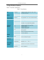
1.2 Specifications/Features
Table 1-1 describes specifications.
Table 1-1 Specifications
CPU
Processor
TI, AM3352, ARM Cortex-A8, 32-Bit, 1 GHz
Low Power Processor
Memory
On Board RAM
DDR3, 256 MB
Flash
1 GB
Wireless
Communication
Bluetooth
OPT Bluetooth V4.0, 2.4 GHz Internal Antenna
Peripheral
Interfaces
Ethernet
2 x 1000M
SD card
1 x Micro SD card
COM Port
1 x RS485, 1 x RS232/RS485 (Isolated)
LED
2 x LED for UART2 (RXD and TXD)
2 x LED for UART4 (RXD and TXD)
1 x LED for power
1 x LED for state of error
1 x LED for state of SS
RTC
Supported, separately RTC chip, power for
super capacitor
Control
Button of Restored to Default setting
GPIO
4 x GPIO (Optional)
Software
OS
Linux
Applications
Provide SDK
Power
Input
Wide Range (9-30V DC or 24V AC),
3 x 3.81 mm Black Terminal
Mechanical
Dimensions
155 x 105 x 50 mm (Box)
Install Brackets
100 x 70 x 28 mm
Enclosure
Sheet Metal with Gray Color
Environment
Condition
Temperature
Operating: -20°C ~ +50°C
Storage: -40°C ~ +85°C
Humidity
5-95%RH at 25-35 (Non-Condensation)
Cooling Mode
Fanless
Approvals
RoHS Compliance

FPC-N64 User Manual
3
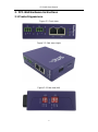
2. FPC-N64 Hardware Instructions
2.1 Product Appearance
Figure 2-1 Front view
Figure 2-2 Side view (right)
Figure 2-3 Side view (left)

FPC-N64 User Manual
4
2.2 Interface Description
2.2.1 Power Interface
Figure 2-4 Power connector outlook
Table 2-2 Pin description of power connector
Pin
Description
1
Power input range: DC9-30V or AC24V L
2
DC Ground or AC24V N
3
Shell ground
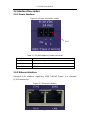
2.2.2 Ethernet Interface
Standard RJ45 interface, supporting 100M Full/Half Duplex, is a standard
RJ45 Ethernet port.
Figure 2-5 Ethernet interface
Pin 1

FPC-N64 User Manual
5
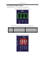
2.2.3 RS232 or RS485 Connector
Standard vertical 1 x 3 x 3.81 mm male Terminal Block.
Figure 2-6 RS232 or RS485 connector
Table 2-3 Pin description of RS232 or RS485 connector
Pin
Description
Remarks
1
TX or RS485_A
IO
2
RX or RS485_B
IO
3
GND
Figure 2-7 DIP Switch for selection

FPC-N64 User Manual
6
Table 2-4 Bit description of RS232 or RS485 connector
Bit
Description
Single
1
ON: Have matched with a resistor of 120 ohm
OFF: No
Term
2
ON: Have pulled up a resistor of 510 ohm
OFF: No
Bias-
3
ON: Have pulled down a resistor of 510 ohm
OFF: No
Bias+
4
ON: Select RS232
OFF: Select RS485
Select RS232 or RS485
2.2.4 RS485 Connector
Standard vertical 1 x 3 x 3.81 mm male Terminal Block.
Figure 2-8 RS485 connector
Table 2-5 Pin description of RS485 connector
Pin
Description
Remarks
1
RS485_A
IO
2
RS485_B
IO
3
GND

FPC-N64 User Manual
7
Figure 2-9 DIP Switch for selection
Table 2-6 Bit description of RS485 connector
Bit
Description
Single
1
ON: Have matched with a resistor of 120 ohm
OFF: No
Term
2
ON: Have pulled up a resistor of 510 ohm
OFF: No
Bias-
3
ON: Have pulled down a resistor of 510 ohm
OFF: No
Bias+
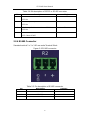
2.2.5 Boot Configuration
Figure 2-10 Boot configuration
SHORT: Boot from NAND
OPEN: Boot from SD/MMC
Boot
Configurati
on

FPC-N64 User Manual
8
2.2.6 LED
PWR LED: If the light is on, the system is successfully started; If the light is off,
the system is turned off.
ERR LED: User can define by themselves.
SS LED: User can define by themselves.
TX LED: If R1 sends data, TX1 flashes; if R2 sends data, TX2 flashes.
RX LED: If R1 receives data, RX1 flashes; if R2 receives data, RX2 flashes.
Figure 2-11 LED
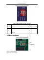
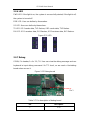
2.2.7 Debug
CONN, Pin header,1 x 4 x 2.0, TH. User can view the debug message and use
keyboard to input debug command. It’s TTL level, so we need a Uart-debug
board when we use it.
Figure 2-12 Debug board
Table 2-7 Pin description of debug board
Pin
Description
1
3.3V
Pin 1

FPC-N64 User Manual
9
2
TTL_TXD
3
TTL_RXD
4
DGND
2.2.8 Renew Button
Renew button: Press and hold this button to restore factory settings, and the
press time is user-defined.
Figure 2-13 Renew button
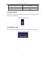
2.2.9 SD/MMC Socket
This is standard SD card socket where user can save data on this storage.
Figure 2-14 SD/MMC socket

FPC-N64 User Manual
10
3. Tips
Waste Disposal
It is recommended to disassemble the device before abandoning it in
conformity with local regulations. Please ensure that the abandoned batteries
are disposed according to local regulations on waste disposal. Do not throw
batteries into fire (explosive) or put in common waste canister. Products or
product packages with the sign of “explosive” should not be disposed like
household waste but delivered to specialized electrical&electronic waste
recycling/disposal center. Proper disposal of this sort of waste helps avoiding
harm and adverse effect upon surroundings and people’s health. Please
contact local organizations or recycling/disposal center for more
recycling/disposal methods of related products.
Comply with the following safety tips:
Do not use in combustible and explosive environment
Keep away from combustible and explosive environment for fear of danger.
Keep away from all energized circuits.
Operators should not remove enclosure from the device. Only the group or
person with factory certification is permitted to open the enclosure to adjust
and replace the structure and components of the device. Do not change
components unless the power cord is removed. In some cases, the device
may still have residual voltage even if the power cord is removed. Therefore, it
is a must to remove and fully discharge the device before contact so as to
avoid injury.
Unauthorized changes to this product or its components are prohibited.
In the aim of avoiding accidents as far as possible, it is not allowed to replace
the system or change components unless with permission and certification.
Please contact the technical department of Vantron or local branches for help.

FPC-N64 User Manual
11
Pay attention to caution signs.
Caution signs in this manual remind of possible danger. Please comply with
relevant safety tips below each sign. Meanwhile, you should strictly conform to
all safety tips for operation environment.
Notice
Considering that reasonable efforts have been made to assure accuracy of this
manual, Vantron assumes no responsibility of possible missing contents and
information, errors in contents, citations, examples, and source programs.
Vantron reserves the right to make necessary changes to this manual without
prior notice. No part of this manual may be reprinted or publicly released in for
FCC Warning
FCC Supplier’s Declaration of Conformity
M2M Gateway / FPC-N64
This device complies with part 15 of the FCC Rules. Operation is subject to the
following two conditions: (1) This device may not cause harmful interference, and
(2) this device must accept any interference received, including interference that
may cause undesired operation.
Vantron Technology, Inc.
440 Boulder Court, Suite 300,
Pleasanton, CA 94566, USA
925-621-8758
Déclaration de conformité du fournisseur de FAC
Passerelle M2M / FPC-N64
Ce dispositif est conforme à la partie 15 des règles de la FCC. L’opération est soumise
aux deux conditions suivantes : (1) Cet appareil ne peut pas causer d’interférences
nocives, et (2) cet appareil doit accepter toute interférence reçue, y compris toute
interférence qui peut causer un fonctionnement indésirable.
Vantron Technology, Inc.
440 Boulder Court, Suite 300,
Pleasanton, CA 94566, États-Unis
925-621-8758

FPC-N64 User Manual
12
Note: This equipment has been tested and found to comply with the limits for a
Class B digital device, pursuant to part 15 of the FCC Rules. These limits are
designed to provide reasonable protection against harmful interference in a
residential installation. This equipment generates, uses and can radiate radio
frequency energy and, if not installed and used in accordance with the
instructions, may cause harmful interference to radio communications.
However, there is no guarantee that interference will not occur in a particular
installation. If this equipment does cause harmful interference to radio or
television reception, which can be determined by turning the equipment off and
on, the user is encouraged to try to correct the interference by one or more of
the following measures:
—Reorient or relocate the receiving antenna.
—Increase the separation between the equipment and receiver.
—Connect the equipment into an outlet on a circuit different from that to which
the receiver is connected.
—Consult the dealer or an experienced radio/TV technician for help.
—Réorienter ou déplacer l’antenne de réception.
—Augmenter la séparation entre l’équipement et le récepteur.
—Connectez l’équipement dans une prise sur un circuit différent de celui auquel le
récepteur est connecté.
—Consultez le concessionnaire ou un technicien expérimenté en radio/télévision pour
obtenir de l’aide.
Any modification to the product is not permitted unless authorized by Vantron.
It’s not allowed to disassemble the product, it is not allowed to replace the
system or change components unless with permission and certification. Please
contact the technical support department of Vantron or local branches for help.
Caution: The user is cautioned that changes or modifications not expressly approved
by the party responsible for compliance could void the user's authority to operate the
equipment.
Attention : L’utilisateur est averti que les modifications ou modifications non expressément
approuvées par la partie responsable de la conformité pourraient annuler le pouvoir de
l’utilisateur d’exploiter l’équipement.

FPC-N64 User Manual
13
IC statement
This device contains licence-exempt transmitter(s)/receiver(s) that comply with Innovation,
Science and Economic Development Canada’s licence-exempt RSS(s). Operation is
subject to the following two conditions:
1. This device may not cause interference.
2. This device must accept any interference, including interference that may cause
undesired operation of the device.
L’émetteur/récepteur exempt de licence contenu dans le présent appareil est conforme
aux CNR d’Innovation, Sciences et Développement économique Canada applicables aux
appareils radio exempts de licence. L’exploitation est autorisée aux deux conditions
suivantes :
1. L’appareil ne doit pas produire de brouillage;
2. L’appareil doit accepter tout brouillage radioélectrique subi, même si le brouillage
est susceptible d’en compromettre le fonctionnement.
Warning!This class B digital apparatus complies with Canadian ICES-003.
Industry Canada ICES-003 Compliance Label:
CAN ICES-3 (B)/NMB-3(B)
Avertissement!Cet appareil numérique de classe B est conforme à l’ICES-003 canadien.
Industrie Canada ICES-003 Étiquette de conformité :
CAN ICES-3 (B)/NMB-3(B)
RF exposure warning
This equipment must be installed and operated in accordance with provide
instructions and the antenna used for this transmitter must be installed to
provide a separation distance of at least 20 cm from all persons and must not
be co-located or operation in conjunction with any other antenna or transmitter.
End-users and installers must be provided with antenna installation
instructions and transmitter operating conditions for satisfying RF exposure

FPC-N64 User Manual
14
compliance.
Cet équipement doit être installé et actionné conformément aux instructions et l’antenne
utilisée pour cet émetteur doit être installée pour fournir une distance de séparation d’au
moins 20 cm de toutes les personnes et ne doit pas être co-localisée ou exploitée en
conjonction avec toute autre antenne ou émetteur. Les utilisateurs finaux et les
installateurs doivent recevoir des instructions d’installation d’antenne et des conditions de
fonctionnement des émetteurs pour satisfaire à la conformité à l’exposition rf.
La page est en cours de chargement...
-
 1
1
-
 2
2
-
 3
3
-
 4
4
-
 5
5
-
 6
6
-
 7
7
-
 8
8
-
 9
9
-
 10
10
-
 11
11
-
 12
12
-
 13
13
-
 14
14
-
 15
15
-
 16
16
-
 17
17
-
 18
18
-
 19
19
-
 20
20
-
 21
21


dans d''autres langues
- English: Vantron FPC-N64 User manual
Documents connexes
Autres documents
-
Retro-Bit TRIBUTE 64 USB Controller Manuel utilisateur
-
Ingenico iUR 250 Integration Manual
-
-
Extron FPC 6000 Manuel utilisateur
-
 Helvei VR Bluetooth controller Operation Manual Android
-
-
Schneider Electric EBIOTPGW Guide d'installation
-
Baumer MSIA 68 planetary gear transmission Profibus Fiche technique
-
-
Juniper SRX-MP-WLAN-US How To Install
