
FPC 6000
User Guide
Matrix Switcher Accessories
Front Panel Controller
68-3259-01 Rev. C
01 20
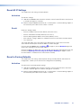
MATRIX SWITCHER CONTROLLER
FPC 6000
MA
TRIX SWITCHE
R CONTROLLE
E
A
A
R
R
F
FPC 60
0
0

Safety Instructions
Safety Instructions • English
WARNING: This symbol, ,when used on the product, is
intended to alert the user of the presence of uninsulated dangerous
voltage within the product’s enclosure that may present a risk of electric
shock.
ATTENTION: This symbol, , when used on the product, is intended
to alert the user of important operating and maintenance (servicing)
instructions in the literature provided with the equipment.
For information on safety guidelines, regulatory compliances, EMI/EMF
compatibility, accessibility, and related topics, see the Extron Safety and
Regulatory Compliance Guide, part number 68-290-01, on the Extron
website, www.extron.com.
Sicherheitsanweisungen • Deutsch
WARNUNG: Dieses Symbol auf dem Produkt soll den Benutzer
darauf aufmerksam machen, dass im Inneren des Gehäuses dieses
Produktes gefährliche Spannungen herrschen, die nicht isoliert sind und
die einen elektrischen Schlag verursachen können.
VORSICHT: Dieses Symbol auf dem Produkt soll dem Benutzer in
der im Lieferumfang enthaltenen Dokumentation besonders wichtige
Hinweise zur Bedienung und Wartung (Instandhaltung) geben.
Weitere Informationen über die Sicherheitsrichtlinien, Produkthandhabung,
EMI/EMF-Kompatibilität, Zugänglichkeit und verwandte Themen finden Sie in
den Extron-Richtlinien für Sicherheit und Handhabung (Artikelnummer
68-290-01) auf der Extron-Website, www.extron.com.
Instrucciones de seguridad • Español
ADVERTENCIA: Este símbolo, , cuando se utiliza en el producto,
avisa al usuario de la presencia de voltaje peligroso sin aislar dentro del
producto, lo que puede representar un riesgo de descarga eléctrica.
ATENCIÓN: Este símbolo, , cuando se utiliza en el producto, avisa
al usuario de la presencia de importantes instrucciones de uso y
mantenimiento recogidas en la documentación proporcionada con el
equipo.
Para obtener información sobre directrices de seguridad, cumplimiento
de normativas, compatibilidad electromagnética, accesibilidad y temas
relacionados, consulte la Guía de cumplimiento de normativas y seguridad
de Extron, referencia 68-290-01, en el sitio Web de Extron, www.extron.com.
Instructions de sécurité • Français
AVERTISSEMENT : Ce pictogramme, , lorsqu’il est utilisé sur le
produit, signale à l’utilisateur la présence à l’intérieur du boîtier du
produit d’une tension électrique dangereuse susceptible de provoquer
un choc électrique.
ATTENTION : Ce pictogramme, , lorsqu’il est utilisé sur le produit,
signale à l’utilisateur des instructions d’utilisation ou de maintenance
importantes qui se trouvent dans la documentation fournie avec le
matériel.
Pour en savoir plus sur les règles de sécurité, la conformité à la
réglementation, la compatibilité EMI/EMF, l’accessibilité, et autres sujets
connexes, lisez les informations de sécurité et de conformité Extron, réf.
68-290-01, sur le site Extron, www.extron.com.
Istruzioni di sicurezza • Italiano
AVVERTENZA: Il simbolo, , se usato sul prodotto, serve ad
avvertire l’utente della presenza di tensione non isolata pericolosa
all’interno del contenitore del prodotto che può costituire un rischio di
scosse elettriche.
ATTENTZIONE: Il simbolo, , se usato sul prodotto, serve ad
avvertire l’utente della presenza di importanti istruzioni di funzionamento
e manutenzione nella documentazione fornita con l’apparecchio.
Per informazioni su parametri di sicurezza, conformità alle normative,
compatibilità EMI/EMF, accessibilità e argomenti simili, fare riferimento
alla Guida alla conformità normativa e di sicurezza di Extron, cod. articolo
68-290-01, sul sito web di Extron, www.extron.com.
Instrukcje bezpieczeństwa • Polska
OSTRZEŻENIE: Ten symbol, , gdy używany na produkt, ma na celu
poinformować użytkownika o obecności izolowanego i niebezpiecznego
napięcia wewnątrz obudowy produktu, który może stanowić zagrożenie
porażenia prądem elektrycznym.
UWAGI: Ten symbol, , gdy używany na produkt, jest przeznaczony do
ostrzegania użytkownika ważne operacyjne oraz instrukcje konserwacji
(obsługi) w literaturze, wyposażone w sprzęt.
Informacji na temat wytycznych w sprawie bezpieczeństwa, regulacji
wzajemnej zgodności, zgodność EMI/EMF, dostępności i Tematy pokrewne,
zobacz Extron bezpieczeństwa i regulacyjnego zgodności przewodnik, część
numer 68-290-01, na stronie internetowej Extron, www.extron.com.
Инструкция по технике безопасности • Русский
ПРЕДУПРЕЖДЕНИЕ: Данный символ, , если указан
на продукте, предупреждает пользователя о наличии
неизолированного опасного напряжения внутри корпуса
продукта, которое может привести к поражению
электрическим током.
ВНИМАНИЕ: Данный символ, , если указан на продукте,
предупреждает пользователя о наличии важных инструкций
по эксплуатации и обслуживанию в руководстве,
прилагаемом к данному оборудованию.
Для получения информации о правилах техники безопасности,
соблюдении нормативных требований, электромагнитной
совместимости (ЭМП/ЭДС), возможности доступа и других
вопросах см. руководство по безопасности и соблюдению
нормативных требований Extron на сайте Extron: ,
www.extron.com, номер по каталогу - 68-290-01.
安全说明 • 简体中文
警告: 产品上的这个标志意在警告用户该产品机壳内有暴露的危险 电压,
有触电危险。
注意: 产品上的这个标志意在提示用户设备随附的用户手册中有
重要的操作和维护(维修)说明。
关于我们产品的安全指南、遵循的规范、EMI/EMF 的兼容性、无障碍
使用的特性等相关内容,敬请访问 Extron 网站 , www.extron.com,参见
Extron 安全规范指南,产品编号 68-290-01。

Copyright
© 2017-2020 Extron Electronics. All rights reserved. www.extron.com
Trademarks
All trademarks mentioned in this guide are the properties of their respective owners.
The following registered trademarks (
®
), registered service marks (
SM
), and trademarks (
TM
) are the property of RGBSystems, Inc. or
ExtronElectronics (see the current list of trademarks on the Terms of Use page at www.extron.com):
Registered Trademarks
(
®
)
Cable Cubby, ControlScript, CrossPoint, DTP, eBUS, EDID Manager, EDID Minder, Extron, Flat Field, FlexOS, Glitch Free, Global Configurator,
Global Scripter, GlobalViewer, Hideaway, HyperLane, IPIntercom, IPLink, Key Minder, LinkLicense, LockIt, MediaLink, MediaPort, NetPA,
PlenumVault, PoleVault, PowerCage, PURE3, Quantum, ShareLink, Show Me, SoundField, SpeedMount, SpeedSwitch, StudioStation,
System INTEGRATOR, TeamWork, TouchLink, V-Lock, VideoLounge, VN-Matrix, VoiceLift, WallVault, WindoWall, XPA, XTP, XTP Systems, and
ZipClip
Registered Service Mark
(SM)
: S3 Service Support Solutions
Trademarks
(
™
)
AAP, AFL (Accu-Rate Frame Lock), ADSP (Advanced Digital Sync Processing), Auto-Image, AVEdge, CableCover, CDRS (Class D
Ripple Suppression), Codec Connect, DDSP (Digital Display Sync Processing), DMI (Dynamic Motion Interpolation), DriverConfigurator,
DSPConfigurator, DSVP (Digital Sync Validation Processing), eLink, EQIP, Everlast, FastBite, Flex55, FOX, FOXBOX, IP Intercom HelpDesk,
MAAP, MicroDigital, Opti-Torque, PendantConnect, ProDSP, QS-FPC (QuickSwitch Front Panel Controller), Room Agent, Scope-Trigger, SIS,
Simple Instruction Set, Skew-Free, SpeedNav, Triple-Action Switching, True4K, True8K, Vector™ 4K, WebShare, XTRA, and ZipCaddy
안전 지침 • 한국어
경고: 이 기호 가 제품에 사용될 경우, 제품의 인클로저 내에 있는
접지되지 않은 위험한 전류로 인해 사용자가 감전될 위험이 있음을
경고합니다.
주의: 이 기호 가 제품에 사용될 경우, 장비와 함께 제공된 책자에 나와
있는 주요 운영 및 유지보수(정비) 지침을 경고합니다.
안전 가이드라인, 규제 준수, EMI/EMF 호환성, 접근성, 그리고 관련 항목에
대한 자세한 내용은 Extron 웹 사이트(www.extron.com)의 Extron 안전 및
규제 준수 안내서, 68-290-01 조항을 참조하십시오.
安全記事 • 繁體中文
警告: 若產品上使用此符號,是為了提醒使用者,產品機殼內存在著
可能會導致觸電之風險的未絕緣危險電壓。
注意 若產品上使用此符號,是為了提醒使用者,設備隨附的用戶手冊中有
重 要 的 操 作 和 維 護( 維 修 )説 明 。
有關安全性指導方針、法規遵守、EMI/EMF 相容性、存取範圍和相關主題的詳細資
訊,請瀏覽 Extron 網站:www.extron.com,然後參閱《Extron 安全性與法規
遵守手冊》,準則編號 68-290-01。
安全上のご注意 • 日本語
警告: この記号 が製品上に表示されている場合は、筐体内に絶縁されて
いない高電圧が流れ、感電の危険があることを示しています。
注意:この記号 が製品上に表示されている場合は、本機の取扱説明書に
記載されている重要な操作と保守(整備)の指示についてユーザーの注意
を喚起するものです。
安全上のご注意、法規厳守、EMI/EMF適合性、その他の関連項目に
つ い て は 、エ ク スト ロ ン の ウェ ブ サ イト www.extron.com よ り 『 Extron Safety
and Regulatory Compliance Guide』 ( P/N 68-290-01) をご覧ください。

FCC Class A Notice
This equipment has been tested and found to comply with the limits for a Class A digital
device, pursuant to part15 of the FCC rules. The ClassA limits provide reasonable protection
against harmful interference when the equipment is operated in a commercial environment.
This equipment generates, uses, and can radiate radio frequency energy and, if not installed
and used in accordance with the instruction manual, may cause harmful interference to radio
communications. Operation of this equipment in a residential area is likely to cause interference.
This interference must be corrected at the expense of the user.
NOTE: For more information on safety guidelines, regulatory compliances, EMI/EMF
compatibility, accessibility, and related topics, see the Extron Safety and Regulatory
Compliance Guide on the Extron website.
Battery Notice
This product contains a battery. Do not open the unit to replace the battery. If the
battery needs replacing, return the entire unit to Extron (for the correct address, see the Extron
Warranty section on the last page of this guide).
CAUTION: Risk of explosion if battery is replaced by an incorrect type. Dispose of used
batteries according to the instructions.
ATTENTION : Risque d’explosion. Ne pas remplacer la pile par le mauvais type de pile.
Débarrassez-vous des piles utilisées selon le mode d’emploi.

Conventions Used in this Guide
Notifications
In this user guide, the following are used:
WARNING: Potential risk of severe injury or death.
AVERTISSEMENT : Risque potentiel de blessure grave ou de mort.
CAUTION: Risk of minor personal injury.
ATTENTION : Risque de blessuremineure.
ATTENTION:
• Risk of property damage.
• Risque de dommages matériels.
NOTE: A note draws attention to important information.
Software Commands
Commands are written in the fonts shown here:
^AR Merge Scene,,Op1 scene 1,1 ^B 51 ^W^C
[01] R 0004 00300 00400 00800 00600 [02] 35 [17] [03]
E
X!
*
X1&
*
X2)
*
X2#
*
X2!
CE
}
NOTE: For commands and examples of computer or device responses mentioned
in this guide, the character “0” is used for the number zero and “O” represents the
capital letter “o”.
Computer responses and directory paths that do not have variables are written in the font shown
here:
Reply from 208.132.180.48: bytes=32 times=2ms TTL=32
C:\Program Files\Extron
Variables are written in slanted form as shown here:
ping xxx.xxx.xxx.xxx —t
SOH R Data STX Command ETB ETX
Selectable items, such as menu names, menu options, buttons, tabs, and field names are written
in the font shown here:
From the File menu, select New.
Click the OK button.
Specifications Availability
Product specifications are available on the Extron website, www.extron.com.
Extron Glossary of Terms
A glossary of terms is available at www.extron.com/technology/glossary.aspx.


Contents
Introduction............................................................ 1
About This Guide ....................................................1
About the FPC 6000 ...............................................1
Features .................................................................. 1
Application Diagram ................................................2
Matrix Switcher Terms ............................................. 3
Installation Overview ........................................... 4
Mounting ................................................................. 6
Installing the FPC 6000 in a Rack
or Control Console ................................................. 6
Underwriters Laboratories Guidelines for
Rack Mounting .......................................................7
Wall Mounting the FPC 6000 ...................................7
Panel Features ...................................................... 9
Front Panel Features ...............................................9
Rear Panel Features ..............................................10
Setup Menu .......................................................... 13
Setup Menu ..........................................................13
Status ...............................................................13
Network ............................................................ 14
Display .............................................................. 16
Audio ................................................................17
Advanced .........................................................18
FPC 6000 Web Page ........................................... 19
FPC 6000 Web Page ............................................19
Updating the Firmware ..........................................20
Downloading Firmware ......................................20
Updating Firmware Using the Touchpanel
Web Page ........................................................ 21
Operation .............................................................. 22
Login Screen ......................................................... 22
Ties Screen ........................................................... 24
Menu Buttons ...................................................25
Input Buttons ....................................................25
Output Buttons .................................................25
Mute Selection Buttons ..................................... 26
Mute Control Button .........................................26
Select All ........................................................... 26
Take .................................................................. 26
Break ................................................................26
Clear Selection ..................................................26
Create a Tie ......................................................27
Break A Tie .......................................................28
Change View.....................................................30
Presets .............................................................32
Status Screen .......................................................37
I/O Info Screen ......................................................37
Customize Screen ................................................. 39
Reset Modes ........................................................ 40
Use Factory Firmware ...........................................40
Activation ..........................................................40
Result ...............................................................40
Reset All IP Settings .............................................. 41
Activation ..........................................................41
Result ...............................................................41
Reset to Factory Defaults ......................................41
Activation ..........................................................41
Result ...............................................................42
FPC 6000 • Contents vii

FPC 6000 • Contents viii

Introduction
• About This Guide
• About the FPC 6000
• Features
• Application Diagram
• Matrix Switcher Terms
About This Guide
This guide describes how to install, configure, and operate the Extron FPC 6000 Front Panel
Controller. Unless otherwise stated, the terms “Front Panel Controller,” “touchpanel,” and “FPC”
refer to the Extron FPC 6000.
About the FPC 6000
The FPC 6000 uses an Extron TLP Pro 1520M TouchLink touchscreen to provide an intuitive,
15-inch control interface with straightforward menus for quick and easy system configuration.
The FPC 6000 is a stand-alone device that does not require an additional external controller or
configuration with Global Configurator Plus and Professional or GUI Designer software.
The FPC 6000 supports the following Extron matrix switchers:
• FOX 3200 Matrix
• FOX 7200 Matrix
• FOX 14400 Matrix
• FOX 320x Matrix
NOTE: Additional matrix switchers will be added in the future. See www.extron.com for
the most recent information about compatible matrix switchers.
Features
• Compatible with the Extron FOX 3200 Matrix, FOX 7200 Matrix, FOX 14400 Matrix,
and FOX 320x Matrix
• Intuitive, menu-driven 15" color touchscreen control interface
• Global presets — FOX 3200 models support up to 32 global presets. Other models
support up to 64 global presets. This time-saving feature allows frequently used I/O
configurations to be saved, stored in memory, and recalled using the FPC 6000.
• Rooming — Provides up to 10 presets for each of 10 virtual rooms for a total of up to 100
rooming presets for added flexibility and control in routing signals.
• Remote monitoring, access, and management of all set-up and control functions
• Ethernet capabilities — For matrix control from one or more locations over a local area
network
• Multiple matrix control — The controller is capable of storing up to ten IP addresses.
• 7U, rack-mountable panel — Can also be installed in a control console.
• Includes a PI 140 Power Injector — The FPC 6000 receives power and communication
over a single Ethernet cable, eliminating the need for a local power supply.
FPC 6000 • Introduction 1

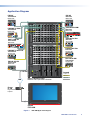
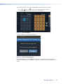
Application Diagram
FOX AV Rx
Y/VID
O
U
T
P
U
T
S
RS-232
OVER FIBER
RS-232
REMOTE
Tx Rx Tx Rx
AUDIO
LR
RxTx
ALARM
12
R-Y
B-Y/C
S-VID
OPTICAL
POWER
12V
0.8A MAX
FOX AV Tx
Y/VID
I
N
P
U
T
S
RS-232
OVER FIBER
RS-232
REMOTE
Tx Rx Tx Rx
AUDIO
LR
ALARM
12
R-Y
B-Y/C
S-VID
OPTICAL
POWER
12V
0.8A MAX
RxTx
FOXBOX SR HDMI
LINK
LINK
OPTICAL
RxTx
HDMI
AUDIO
OUTPUTS
REMOTE
RS-232
Tx Rx
RS-232
OVER FIBER
ALARM
Tx Rx 1 2
POWER
12V
1.0 A MAX
LR
OFF
ON
HDMI AUDIO
FOXBOX SR HDMI
AUDIO
HDCP
VIDEO
CONFIG
MENU ENTER
ADJUST
ADJU
FO
FO
FOX
FOX
FOXB
FOXBOX
ST
FOXBOX Rx VGA
RGB
OVER
TEMP
AUDIO
CONFIG
OPTICAL
Rx
Tx
LINK
LINK
AUDIO
RGB OUTPUT
FOXBOX Rx VGA
RS-232
OVER FIBER
ALARM
Tx Rx 1 2
12V
1.0A MAX
POWER
MODE
1
ON
2
AUDIO
RGB/YUV INPUT
FOXBOX Tx VGA/YUV
RS-232
OVER FIBER
ALARM
Tx Rx 1 2
12V
1.0A MAX
POWER
FOXBOX Tx VGA/YUV
RGB/
YUV
OVER
TEMP
AUDIO
CONFIG
OPTICAL
Rx
Tx
LINK
LINK
12V
1.0A MAX
POWER
FOXBOX Tx HDMI
AUDIO INPUT
RS-232
OVER FIBER
ALARM
Tx Rx 1 2
HDMI
LINK
OPTICAL
RxTx
LINK
FOXBOX Tx HDMI
AUDIO
HDCP
HDMI
CONFIG
HDMI LOOP THRU
EDID MINDER
50Hz
AUDIO
DIGITAL
ANALOG
60Hz
1 2
FOX 3G HD-SDI
UNKNOWN
2.97
Gbps
1.485
Gbps
RATE
270
Mbps
FOX 3G HD-SDI
UNKNOWN
2.97
Gbps
1.485
Gbps
RATE
270
Mbps
100-240V
50/60 Hz
---A MAX
INPUT
LAN POWERED TLP
OUTPUT
12V
0.3A MAX
FOX 3G HD-SDI
HD/SDI IN
POWER
BUFFERED OUTPUTS
MODE
OPTICAL
RxTx
12
12
ON
12V
0.3A MAX
FOX 3G HD-SDI
HD/SDI IN
POWER
BUFFERED OUTPUTS
MODE
OPTICAL
RxTx
12
12
ON
FOXBOX Rx DVI Plus
DVI
OVER
TEMP
AUDIO
CONFIG
OPTICAL
Rx
Tx
LINK
LINK
AUDIO
DVI-D OUTPUT
FOXBOX Rx DVI Plus
RS-232
OVER FIBER
ALARM
Tx Rx 1 2
12V
1.0A MAX
POWER
MODE
1
ON
2
FOX Tx AV
VIDEO FIBER OPTIC TRANSMITTER
COMPOSITE
FORMAT
S-VIDEO
COMPONENT
AUDIO
AUTO
CONFIG
FOX T USW 103
RS-232CONTACT
RS-232
OVER FIBER
AUDIO
HDMIHDMIRGB/R-Y, Y, B-Y
ALARM
REMOTE
Tx Rx
Tx Rx
OPTICAL
INPUTS
1
POWER
12V
0.7 A MAX
23
LINK
LINK
GTxRxG12 123G
FOX T USW 103
AUTO
SWITCH
MODE
CONFIG
NORMAL
1 2
AUTO
SIGNAL
HDCP
STATUS
3
123
FOX Rx AV
VIDEO FIBER OPTIC RECEIVER
COMPOSITE
FORMAT
S-VIDEO
COMPONENT
AUDIO
LOOP-OUT
FOLLOW
CONFIG
MM R
SM R
MM R
SM R
MM R
SM R
MM R
SM R
MM R
SM R
MM R
SM R
MM R
SM R
MM R
SM R
MM R
SM R
MM R
SM R
ANAHEIM, CA
RESET
RS232/RS422
REMOTE
LAN
ACT
LINK
100-240V
50/60Hz
6.4A MAX.
100-240V
50/60Hz
6.4A MAX.
REDUNDANT
PRIMARY
DISCONNECT BOTH POWER
CORDS BEFORE SERVICING
1 - 16
17 - 32
33 - 48
49 - 64
65 - 80
81 - 96
97 - 112
113 - 128
129 - 144145 - 160
FAN ASSIMBLY
FAN ASSIMBLY
PRIMARY POWER SUPPLY 1
REDUNDANT POWER SUPPLY 1
PRIMARY POWER SUPPLY 2
REDUNDANT POWER SUPPLY 2
161 - 176
177 - 192
193 - 208
209 - 224
225 - 240
241 - 256
257 - 272
273 - 288
289 - 304305 - 320
FAN ASSIMBLY
FAN ASSIMBLY
OUT
IN
OUT
IN
OUT
IN
OUT
IN
OUT
IN
OUT
IN
OUT
IN
OUT
IN
OUT
IN
OUT
IN
OUT
IN
OUT
IN
OUT
IN
OUT
IN
OUT
IN
OUT
IN
BCDEFGHI JKLMNOP
A
OUT
IN
OUT
IN
OUT
IN
OUT
IN
OUT
IN
OUT
IN
OUT
IN
OUT
IN
OUT
IN
OUT
IN
OUT
IN
OUT
IN
OUT
IN
OUT
IN
OUT
IN
OUT
IN
BCDEFGHI JKLMNOP
A
OUT
IN
OUT
IN
OUT
IN
OUT
IN
OUT
IN
OUT
IN
OUT
IN
OUT
IN
OUT
IN
OUT
IN
OUT
IN
OUT
IN
OUT
IN
OUT
IN
OUT
IN
OUT
IN
BCDEFGHI JKLMNOP
A
OUT
IN
OUT
IN
OUT
IN
OUT
IN
OUT
IN
OUT
IN
OUT
IN
OUT
IN
OUT
IN
OUT
IN
OUT
IN
OUT
IN
OUT
IN
OUT
IN
OUT
IN
OUT
IN
BCDEFGHI JKLMNOP
A
OUT
IN
OUT
IN
OUT
IN
OUT
IN
OUT
IN
OUT
IN
OUT
IN
OUT
IN
OUT
IN
OUT
IN
OUT
IN
OUT
IN
OUT
IN
OUT
IN
OUT
IN
OUT
IN
BCDEFGHI JKLMNOP
A
OUT
IN
OUT
IN
OUT
IN
OUT
IN
OUT
IN
OUT
IN
OUT
IN
OUT
IN
OUT
IN
OUT
IN
OUT
IN
OUT
IN
OUT
IN
OUT
IN
OUT
IN
OUT
IN
BCDEFGHI JKLMNOP
A
OUT
IN
OUT
IN
OUT
IN
OUT
IN
OUT
IN
OUT
IN
OUT
IN
OUT
IN
OUT
IN
OUT
IN
OUT
IN
OUT
IN
OUT
IN
OUT
IN
OUT
IN
OUT
IN
BCDEFGHI JKLMNOP
A
OUT
IN
OUT
IN
OUT
IN
OUT
IN
OUT
IN
OUT
IN
OUT
IN
OUT
IN
OUT
IN
OUT
IN
OUT
IN
OUT
IN
OUT
IN
OUT
IN
OUT
IN
OUT
IN
BCDEFGHI JKLMNOP
A
OUT
IN
OUT
IN
OUT
IN
OUT
IN
OUT
IN
OUT
IN
OUT
IN
OUT
IN
OUT
IN
OUT
IN
OUT
IN
OUT
IN
OUT
IN
OUT
IN
OUT
IN
OUT
IN
BCDEFGHI JKLMNOP
A
OUT
IN
OUT
IN
OUT
IN
OUT
IN
OUT
IN
OUT
IN
OUT
IN
OUT
IN
OUT
IN
OUT
IN
OUT
IN
OUT
IN
OUT
IN
OUT
IN
OUT
IN
OUT
IN
BCDEFGHI JKLMNOP
A
OUT
IN
OUT
IN
OUT
IN
OUT
IN
OUT
IN
OUT
IN
OUT
IN
OUT
IN
OUT
IN
OUT
IN
OUT
IN
OUT
IN
OUT
IN
OUT
IN
OUT
IN
OUT
IN
BCDEFGHI JKLMNOP
A
OUT
IN
OUT
IN
OUT
IN
OUT
IN
OUT
IN
OUT
IN
OUT
IN
OUT
IN
OUT
IN
OUT
IN
OUT
IN
OUT
IN
OUT
IN
OUT
IN
OUT
IN
OUT
IN
BCDEFGHI JKLMNOP
A
OUT
IN
OUT
IN
OUT
IN
OUT
IN
OUT
IN
OUT
IN
OUT
IN
OUT
IN
OUT
IN
OUT
IN
OUT
IN
OUT
IN
OUT
IN
OUT
IN
OUT
IN
OUT
IN
BCDEFGHI JKLMNOP
A
OUT
IN
OUT
IN
OUT
IN
OUT
IN
OUT
IN
OUT
IN
OUT
IN
OUT
IN
OUT
IN
OUT
IN
OUT
IN
OUT
IN
OUT
IN
OUT
IN
OUT
IN
OUT
IN
BCDEFGHI JKLMNOP
A
OUT
IN
OUT
IN
OUT
IN
OUT
IN
OUT
IN
OUT
IN
OUT
IN
OUT
IN
OUT
IN
OUT
IN
OUT
IN
OUT
IN
OUT
IN
OUT
IN
OUT
IN
OUT
IN
BCDEFGHI JKLMNOP
A
OUT
IN
OUT
IN
OUT
IN
OUT
IN
OUT
IN
OUT
IN
OUT
IN
OUT
IN
OUT
IN
OUT
IN
OUT
IN
OUT
IN
OUT
IN
OUT
IN
OUT
IN
OUT
IN
BCDEFGHI JKLMNOP
A
OUT
IN
OUT
IN
OUT
IN
OUT
IN
OUT
IN
OUT
IN
OUT
IN
OUT
IN
OUT
IN
OUT
IN
OUT
IN
OUT
IN
OUT
IN
OUT
IN
OUT
IN
OUT
IN
BCDEFGHI JKLMNOP
A
OUT
IN
OUT
IN
OUT
IN
OUT
IN
OUT
IN
OUT
IN
OUT
IN
OUT
IN
OUT
IN
OUT
IN
OUT
IN
OUT
IN
OUT
IN
OUT
IN
OUT
IN
OUT
IN
BCDEFGHI JKLMNOP
A
OUT
IN
OUT
IN
OUT
IN
OUT
IN
OUT
IN
OUT
IN
OUT
IN
OUT
IN
OUT
IN
OUT
IN
OUT
IN
OUT
IN
OUT
IN
OUT
IN
OUT
IN
OUT
IN
BCDEFGHI JKLMNOP
A
OUT
IN
OUT
IN
OUT
IN
OUT
IN
OUT
IN
OUT
IN
OUT
IN
OUT
IN
OUT
IN
OUT
IN
OUT
IN
OUT
IN
OUT
IN
OUT
IN
OUT
IN
OUT
IN
BCDEFGHI JKLMNOP
A
MM R
SM R
MM R
SM R
MM R
SM R
MM R
SM R
MM R
SM R
MM R
SM R
MM R
SM R
MM R
SM R
SM R
MM R
MM R
SM R
MATRIX SWITCHER CONTROLLER
FPC 6000
FOXBOX SR HDMI
Receiver
Multimode
FOX AV
Receiver
Multimode
FOXBOX DVI Plus
Receiver
Singlemode
FOXBOX Rx VGA
Receiver
Singlemode
FOX 3G HD-SDI
Transceiver
Singlemode
FO
XBOX Tx HDMI
Tr
ansmitter
Multimod
e
FO
X AV
Tr
ansmitter
Multimod
e
FO
XBOX Tx VGA/YUV
Tr
ansmitter
Singlemode
FO
X T USW 103
Tr
ansmitter
Multimod
e
FO
X 3G HD-SDI
Tr
ansceiver
Multimod
e
Extron FOX Matrix 320x
Modular Fiber Optic Matrix Switcher
Singlemode
Multimode
Extron
FPC 6000
Legend
Ext
ron
PI
140
High
Power
Inje
ctor
LAN
Ethernet
Figure 1. FPC 6000 Application Diagram
FPC 6000 • Introduction 2

Matrix Switcher Terms
The following terms, which are used throughout this guide, apply to Extron matrix switchers:
• Tie — An input-to-output connection.
• Set of ties — An input tied to two or more outputs. (An output can never be tied to more
than one input).
• Configuration — One tie or one or more sets of ties.
• Current configuration — The configuration that is currently being used (also called
Configuration 0).
• Global memory preset — A configuration that has been stored. FOX 3200 models support
up to 32 global presets. Other models support up to 64 global presets. When a global preset
is retrieved from memory, it becomes the current configuration.
• Room — A room consists of a smaller subset of virtual outputs that are logically related
to each other, as determined by the operator. All FOX matrix switchers support up to
10 rooms, each of which consists of from 1 to 16 virtual outputs. Each room can have up to
10 presets.
• Room memory preset — A configuration consisting of virtual outputs in a single room
that has been stored. When a room preset is retrieved from memory, it becomes the current
configuration.
• SFP — Small form-factor pluggable. The SFP is an interface used in fiber optic connections
for direct signal connections or packet switched networks.
NOTE: The number of rooms and presets that are available depends on the matrix
switcher that is connected to the FPC 6000. See the user guide for the matrix switcher at
www.extron.com for further information.
FPC 6000 • Introduction 3

Installation
Overview
This section provides an overview of the installation process. Follow the links for a more detailed
explanation of each step.
The FPC 6000 consists of:
• (1) 15" touchpanel
• (1) PoE power injector
• (1) 7U high, 19 inch wide, rack-mountable metal panel
1. Obtain the following network information from your network administrator:
Dynamic Host Configuration Protocol (DHCP) status (on or off). If DHCP is off, you
also require:
IP address for the FPC 6000
Subnet mask for the FPC 6000
Gateway for the FPC 6000
User name for the FPC 6000 — By default, this is admin
Password for the FPC 6000
NOTES:
• The factory configured passwords for all accounts on this device have been set
to the device serial number. Passwords are case sensitive.
• If the device is reset to default settings, the password will be the default
password configuration. The default password is extron.
• To change the password, you must use the Extron Toolbelt utility (see the
Toolbelt Help File). Talk to your Extron rep about obtaining a license for
Toolbelt.
IP address for the matrix switcher
Password for the matrix switcher — See the user guide for your matrix switcher for
information about the password.
2. Decide where the FPC 6000 will be mounted (see Mounting on page 6).
3. Cable the unit:
If you are using the provided PoE power injector, connect the FPC 6000 to the
power injector and connect the power injector to the Ethernet LAN (see figure 6 on
page 11).
If you are using a 12 VDC power supply (not provided), connect the FPC 6000 directly
to the LAN (see XTP/LAN/PoE input on page 11) and connect the power supply to
FPC 6000.
ATTENTION:
• Do not power on the FPC 6000 until you have read the Attention
notifications about power supplies (see page 11).
• Ne branchez pas le FPC 6000 avant d’avoir lu les mises en garde sur les
sources d’alimentation (voir page 11).
FPC 6000 • Installation Overview 4


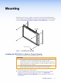
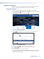
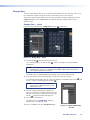
Mounting
When the FPC 6000 ships, it is housed in a 7U high, 19 inch wide, rack-mountable panel that
can be installed in any standard equipment rack or control console. Follow the instructions below
and read the Underwriters Laboratories Guidelines for Rack Mounting on the next page.
e
e
FPC 6000
#10-32 screws (4)
Figure 2. Rack Mounting the FPC 6000
Installing the FPC 6000 in a Rack or Control Console
The FPC 6000 is housed in a rack-mountable panel when it ships.
ATTENTION:
• All structural steps and electrical installation must be performed by qualified personnel
in accordance with local and national building codes and electrical codes.
• Toute étape structurelle et installation électrique, doit être effectuée par un personnel
qualifié, conformément aux codes du bâtiment, aux codes incendie et sécurité, et aux
codes électriques, locaux et nationaux.
• Do not install the FPC 6000 in a fire resistant rated wall or partition assembly.
• Ne pas installer le FPC 6000 dans un mur résistant au feu ou une cloison.
1. Decide where the FPC 6000 will be mounted.
2. Use the four provided rack-mounting screws to secure the FPC 6000 to any standard
equipment rack or control console. Follow the instructions in the Underwriters
Laboratories Guidelines for Rack Mounting (see the next page) to ensure the rack is
mounted safely.
figure 2
FPC 6000 • Mounting 6

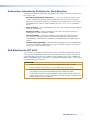
Underwriters Laboratories Guidelines for Rack Mounting
The following Underwriters Laboratories (UL) guidelines are relevant to the safe installation of the
FPC 6000 in a rack:
• Elevated operating ambient temperature — If the unit is installed in a closed or multi-
unit rack assembly, the operating ambient temperature of the rack environment may be
greater than room ambient temperature. Therefore, install the equipment in an environment
compatible with the maximum ambient temperature (Tma: +104 °F, +40 °C) specified by
Extron.
• Reduced air flow — Install the equipment in the rack so that the equipment gets adequate
air flow for safe operation.
• Mechanical loading — Mount the equipment in the rack so that uneven mechanical
loading does not create a hazardous condition.
• Circuit overloading — Connect the equipment to the supply circuit and consider the
effect that circuit overloading might have on overcurrent protection and supply wiring.
Give appropriate consideration to the equipment nameplate ratings when addressing this
concern.
• Reliable earthing (grounding) — Maintain reliable grounding of rack-mounted equipment.
Pay particular attention to supply connections other than direct connections to the branch
circuit (such as the use of power strips).
Wall Mounting the FPC 6000
The FPC 6000 can also be wall-mounted, either using the Extron BB 700M wall box or directly
into drywall. Some local building codes require the touchpanel to be mounted in a wall box. To
use the BB 700M, see the TLP Pro 1220MG, TLP Pro 1520MG, and TLP Pro 1720MG Setup
Guide, at www.extron.com. If the wall box is not required by local building codes, you can mount
the touchpanel directly into drywall.
ATTENTION:
• Do not install the FPC 6000 in a fire resistant rated wall or partition assembly.
• Ne pas installer le FPC 6000 dans un mur résistant au feu ou une cloison.
• All structural steps and electrical installation must be performed by qualified personnel
in accordance with local and national building codes and electrical codes.
• Toute étape structurelle et installation électrique, doit être effectuée par un personnel
qualifié, conformément aux codes du bâtiment, aux codes incendie et sécurité, et aux
codes électriques, locaux et nationaux.
FPC 6000 • Mounting 7

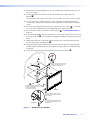
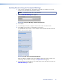
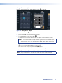
1. Download the cut-out template for the TLP Pro 1520MG from www.extron.com. Print it at
100% (no scaling).
2. Use the template to mark the wall, cut the hole, and drill the four pilot holes (see
figure 3,
1
).
The size of the cut-out hole is 8.90 inches (22.61 cm) wide x 5.70 inches (14.48 cm) high.
3. The FPC 6000 ships, already mounted, in a rack-mountable metal panel. Remove the
FPC 6000 from the panel and, remove the mounting plate that is attached to the panel by
screws.
4. Secure the mounting plate to the mounting surface with four #10 screws (
2
). The installer
must use screws and fasteners that are appropriate for the mounting surface.
5. Run and connect cables to the back of the touchpanel (
3
, see Rear Panel Features on
page 10).
6. Insert the two provided Phillips pan head #6-32 x ¾-inch length screws with washers in the
mounting screw slot (
4
). Leave a gap for the flange at the bottom of the mounting plate to
fit into.
7. Hold the touchpanel at a slight angle and lower the notches at the top of the back panel
over the hooks of the mounting plate (
5
).
8. Swing the bottom of the touchpanel inwards so that it lies flat against the mounting plate
with the flange at the bottom of the mounting plate sitting in a groove in the bottom of the
touchpanel.
9. Secure the touchpanel to the mounting plate with the mounting screws (
6
).
FPC 6000
Back View
Hold the touchpanel at a slight angle
.
Mount the touchpanel over the two
hooks on the mounting plate.
Add the mounting plate. Align with
the wall box and mark holes for screws.
Secure the mounting plate
to the wall with screws (4).
Place the provided mounting screws (2)
with washers in the mounting screw slot
in the touchpanel.
1
Secure the touchpanel by tightening the
mounting screws against the base of the
mounting plate.
1
1
1
2
2
2
3
3
3
4
4
4
5
5
5
6
6
6
Figure 3. Wall Mounting the FPC 6000
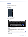
FPC 6000 • Mounting 8

Panel Features
This section describes:
• Front Panel Features
• Rear Panel Features
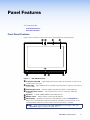
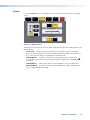
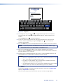
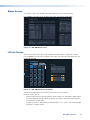
Front Panel Features
Figure 4 shows the front panel of the FPC 6000, removed from the mounting frame.
A
A
AB
B
BC
C
CD
D
D
E
EEEE
EF
F
F G
G
G
Figure 4. FPC 6000 Front Panel
A
Communication LED — Lights briefly when the unit boots up. Otherwise, this LED has no
function on the FPC 6000.
B
Status light — Lights briefly when the unit boots up. Otherwise, this light has no function on
the FPC 6000.
C
Ambient light sensor — Monitors ambient light level and adjusts screen brightness.
D
Capacitive touch screen — The FPC 6000 has a 15.6 inch screen with 1366x768
resolution.
E
Speakers — Provide audible feedback from button presses.
F
Motion sensor — Detects motion in front of the touchpanel.
G
Menu button — Activates the setup menu and calibration screen (see Setup Menu on
page 13). It is accessed from under the touchpanel. It performs the same function as the
rear panel Menu button but is easier to reach when the touchpanel is installed.
NOTE: Extron recommends using the FPC Settings link on the Login screen (see
figure 20 on page 22) to open the setup menu.
figure 4
Communicaton LED
Status light
Ambient light sensor
Capacitive touch screen
Speakers
Motion sensor
Menu button
FPC 6000 • Panel Features 9

Rear Panel Features
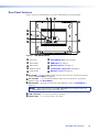
Figure 5 shows the rear panel of the FPC 6000, removed from the mounting frame.
I
I
I
H
H
H
J
J
J
A
A
A
B
B
B
C
C
C
D
D
D
E
E
EF
F
FG
G
G
RESET
MENU
HDMI IN
LAN
POWER
12V
1.0A MAX
Figure 5. FPC 6000 Rear Panel
A
Reset LED
F
XTP/LAN/PoE input (see next page)
B
Reset button
G
HDMI input (see page 12)
C
Menu button
H
Mounting notches (see page 12)
D
USB connectors
I
12 VDC power supply input (see page 12)
E
Audio output
J
Mounting screws (see page 12)
A
Reset LED — Provides feedback about the reset status when the user presses the reset
button (see Reset Modes on page 40)
B
Reset button — Pressing the Reset button allows the unit to be reset in any of three
different modes (see Reset Modes).
C
Menu button — Activates the setup menu and calibration screen (see Setup Menu on
page 13).
NOTE: Extron recommends using the FPC Settings link on the Login screen (see
figure 20 on page 22) to open the setup menu.
D
USB connectors — This has no function in FPC 6000.
E
Audio output — This has no function in FPC 6000.
figure 5
Reset LED
Reset button
Menu button
USB connectors
Audio output
FPC 6000 • Panel Features 10

F
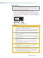
XTP/LAN/PoE input
NOTE: The FPC 6000 can be powered by either the provided PoE power injector
or a 12 VDC, 3 A power supply (which must be purchased separately). Do not
remotely power the touchpanel using an XTP device. Before connecting power to the
FPC 6000, read the Attention notifications below.
• XTP input — Do not connect the FPC 6000 directly to an XTP source.
• LAN input — If you use the provided 12 VDC power supply, connect the FPC 6000
directly to the network using a twisted pair cable, terminated with an RJ-45 connector.
• PoE input — If you use the provided PoE power injector, connect the FPC 6000 to the
power injector output and connect the power injector input to the LAN (see figure 5, on
the previous page).
100-240V~50/60 Hz
1.1A MAX
INPUT OUTPUT
POWERED TLP
LAN
To Network Device
To FPC 6000
Extr
on PI 140
Figure 6. Connecting the Power Injector
ATTENTION:
• Always use a power supply provided by or specified by Extron. Use of an
unauthorized power supply voids all regulatory compliance certification and may
cause damage to the supply and the end product.
• Utilisez toujours une source d’alimentation fournie ou recommandée par Extron.
L’utilisation d’une source d’alimentation non autorisée annule toute conformité
réglementaire et peut endommager la source d’alimentation ainsi que le produit
final.
• The installation must always be in accordance with the applicable provisions of
National Electrical Code ANSI/NFPA 70, article 725 and the Canadian Electrical
Code part 1, section 16.
• Cette installation doit toujours être en accord avec les mesures qui s’applique
au National Electrical Code ANSI/NFPA70, article725, et au Canadian Electrical
Code, partie1, section16.
• These products are intended for use with a UL Listed power source marked
“Class 2” or “LPS” and rated 12VDC, minimum 3.0 A. or 56 VDC (PoE),
minimum 0.8 A.
• Ces produits sont destiné à une utilisation avec une source d’alimentation
listéeUL avec l’appellation «Classe2» ou «LPS» et normée 12Vcc, 3,0A
minimum ou 56Vcc (PoE), 0,8A minimum.
• The power supply shall not be permanently fixed to the building structure or
similar structure.
• La source d’alimentation ne devra pas être fixée de façon permanente à une
structure de bâtiment ou à une structure similaire.
• Power over Ethernet (PoE) is intended for indoor use only. It is to be connected
only to networks or circuits that are not routed to the outside plant or building.
• L’alimentation via Ethernet (PoE) est destinée à une utilisation en intérieur
uniquement. Elle doit être connectée seulement à des réseaux ou des circuits qui
ne sont pas routés au réseau ou au bâtiment extérieur.
XTP/LAN/PoE input
figure 6
mises en garde
Attention notifications
FPC 6000 • Panel Features 11

ATTENTION:
• The touchpanels are intended for connection to a Power over Ethernet circuit for
intra-building use only and are considered to be part of a Network Environment 0
per IEC TR62101.
• Les écrans tactiles sont conçu pour une connexion à un circuit PoE pour une
utilisation intérieure seulement et est considéré comme faisant partie d’un
environnement réseau 0 par IECTR62101.
• Unless otherwise stated, the AC/DC adapters are not suitable for use in air
handling spaces or in wall cavities. The power supply is to be located within the
same vicinity as the Extron AV processing equipment in an ordinary location,
Pollution Degree 2, secured to the equipment rack within the dedicated closet,
podium, or desk.
• Sauf mention contraire, les adaptateurs AC/DC ne sont pas appropriés pour
une utilisation dans les espaces d’aération ou dans les cavités murales. La
source d’alimentation doit être située à proximité de l’équipement de traitement
audiovisuel dans un endroit ordinaire, avec un degré2 de pollution, fixé à un
équipement de rack à l’intérieur d’un placard, d’une estrade, ou d’un bureau.
• Extron power supplies are certified to UL/CSA 60950-1 and are classified as LPS
(Limited Power Source). Use of a non-LPS or unlisted power supply will void all
regulatory compliance certification.
• Les sources d’alimentation Extron sont qualifiées UL/CSA60950-1 et sont
classéesLPS(LimitedPowerSource). L’utilisation d’une source d’alimentation
non-listée ou non-listéeLPS annulera toute certification de conformité
réglementaire.
• The length of the exposed wires in the stripping process is critical. The ideal
length is 3/16 inches (5 mm). If they are any longer, the exposed wires may
touch, causing a short circuit between them. If they are any shorter, the wires can
be easily pulled out even if tightly fastened by the captive screws.
• La longueur des câbles exposés est primordiale lorsque l’on entreprend de les
dénuder. La longueur idéale est de 5mm (3/16inches). S’ils sont un peu plus
longs, les câbles exposés pourraient se toucher et provoquer un court circuit.
S’ils sont un peu plus courts, ils pourraient sortir, même s’ils sont attachés par
les vis captives.
• Do not tin the wire leads before installing into the connector. Tinned wires are not
as secure in the connector and could be pulled out.
• Ne pas étamer les conducteurs avant de les insérer dans le connecteur. Les
câbles étamés ne sont pas aussi bien fixés dans le connecteur et pourraient être
retirés.
G
HDMI input — This has no function in FPC 6000.
H
Mounting notches — Used to attach the mounting plate to the FPC 6000
I
12 VDC power supply input — If you are not using Power over Ethernet, connect a
12 VDC, 3.0 A power supply to this captive screw connector. The power supply must be
purchased separately. Extron recommends the PS 1230 Limited Power Source (LPS).
J
Mounting screws — Used to secure the mounting plate to the FPC 6000.
HDMI input
Mounting notches
12 VDC power supply input
Mounting screws
FPC 6000 • Panel Features 12
La page est en cours de chargement...
La page est en cours de chargement...
La page est en cours de chargement...
La page est en cours de chargement...
La page est en cours de chargement...
La page est en cours de chargement...
La page est en cours de chargement...
La page est en cours de chargement...
La page est en cours de chargement...
La page est en cours de chargement...
La page est en cours de chargement...
La page est en cours de chargement...
La page est en cours de chargement...
La page est en cours de chargement...
La page est en cours de chargement...
La page est en cours de chargement...
La page est en cours de chargement...
La page est en cours de chargement...
La page est en cours de chargement...
La page est en cours de chargement...
La page est en cours de chargement...
La page est en cours de chargement...
La page est en cours de chargement...
La page est en cours de chargement...
La page est en cours de chargement...
La page est en cours de chargement...
La page est en cours de chargement...
La page est en cours de chargement...
La page est en cours de chargement...
La page est en cours de chargement...
La page est en cours de chargement...
-
 1
1
-
 2
2
-
 3
3
-
 4
4
-
 5
5
-
 6
6
-
 7
7
-
 8
8
-
 9
9
-
 10
10
-
 11
11
-
 12
12
-
 13
13
-
 14
14
-
 15
15
-
 16
16
-
 17
17
-
 18
18
-
 19
19
-
 20
20
-
 21
21
-
 22
22
-
 23
23
-
 24
24
-
 25
25
-
 26
26
-
 27
27
-
 28
28
-
 29
29
-
 30
30
-
 31
31
-
 32
32
-
 33
33
-
 34
34
-
 35
35
-
 36
36
-
 37
37
-
 38
38
-
 39
39
-
 40
40
-
 41
41
-
 42
42
-
 43
43
-
 44
44
-
 45
45
-
 46
46
-
 47
47
-
 48
48
-
 49
49
-
 50
50
-
 51
51


dans d''autres langues
- English: Extron FPC 6000 User manual
Documents connexes
-
Extron FOX Matrix 14400 Manuel utilisateur
-
-
-
Extron FOXBOX Rx DVI Plus Manuel utilisateur
-
Extron FOXBOX T HD-SDI Manuel utilisateur
-
-
-
-
-
