Nilfisk-Advance 56212260 Manuel utilisateur
- Catégorie
- Machine à plancher
- Taper
- Manuel utilisateur
Ce manuel convient également à

3/04 revised 10/06 Form Number 56041551
English
AquaMAX™
AX 650
Advance MODEL 56212000
Nilfisk MODEL 56212260
Instructions For Use

2 2
2 2
2 - FORM NO. 56041551 - AquaMAX™ / AX 650
2 ENGLISH2 ENGLISH
2 ENGLISH2 ENGLISH
2 ENGLISH
TABLE OF CONTENTS
Page
Introduction ...................................................................................................................................................................... 3
Parts and Service ............................................................................................................................................................. 3
Nameplate ........................................................................................................................................................................ 3
Uncrating the Machine ...................................................................................................................................................... 3
Important Safety Instructions .............................................................................................................................................. 4
Consignes de Securite Importantes ................................................................................................................................... 5
Know Your Machine ...................................................................................................................................................... 6-7
Functional Description of Controls ..................................................................................................................................... 8
Preparing the Machine for Use
Installing the Batteries ....................................................................................................................................................... 9
Filling the Solution Tank .................................................................................................................................................... 9
Pre-Spraying the Carpet .................................................................................................................................................. 9
Plan for Cleaning .............................................................................................................................................................. 9
Operating the Machine ................................................................................................................................................... 10
Using Attachments .......................................................................................................................................................... 10
After Using the Machine .................................................................................................................................................. 11
Maintenance Schedule ................................................................................................................................................... 11
Maintenance
Pick-Up Tool Maintenance .............................................................................................................................................. 12
Spray Nozzle Maintenance ............................................................................................................................................. 12
Lubricating the Machine .................................................................................................................................................. 12
Cleaning the Vacuum Motor Filters .................................................................................................................................. 12
Adjusting the Brush Height .............................................................................................................................................. 12
Power Brush Maintenance ............................................................................................................................................. 12
Removing the Brush ....................................................................................................................................................... 12
Charging the Batteries .................................................................................................................................................... 13
Checking the Battery Water Level ................................................................................................................................... 13
Battery Maintenance ....................................................................................................................................................... 13
Battery Testing ............................................................................................................................................................... 13
Troubleshooting
Control Circuit Circuit Breaker ......................................................................................................................................... 14
Wheel Drive Circuit Breaker ........................................................................................................................................... 14
Brush Drive Circuit Breaker ............................................................................................................................................ 14
Vacuum Motor Circuit Breaker ........................................................................................................................................ 14
Technical Specifications .................................................................................................................................................. 14

FORM NO. 56041551 - AquaMAX™ / AX 650 - 33
33
3
ENGLISH 3ENGLISH 3
ENGLISH 3ENGLISH 3
ENGLISH 3
INTRODUCTION
This manual will help you get the most from your Nilfisk-Advance AquaMAX™ / AX 650. Read it thoroughly before operating the machine.
Note: Bold numbers in parentheses indicate an item illustrated on pages 6-7.
This product is intended for commercial use only.
PARTS AND SERVICE
Repairs, when required, should be performed by your Authorized Nilfisk-Advance Service Center, who employs factory trained service personnel,
and maintains an inventory of Nilfisk-Advance original replacement parts and accessories.
Call the NILFISK-ADVANCE DEALER named below for repair parts or service. Please specify the Model and Serial Number when discussing
your machine.
(Dealer, affix service sticker here.)
NAME PLATE
The Model Number and Serial Number of your machine are shown on the Nameplate on the machine. This information is needed when ordering
repair parts for the machine. Use the space below to note the Model Number and Serial Number of your machine for future reference.
MODEL NUMBER
SERIAL NUMBER
UNCRATE THE MACHINE
When the machine is delivered, carefully inspect the shipping carton and the machine for damage. If damage is evident, save the shipping carton
so that it can be inspected. Contact the Nilfisk-Advance Customer Service Department immediately to file a freight damage claim.

4 4
4 4
4 - FORM NO. 56041551 - AquaMAX™ / AX 650
4 ENGLISH4 ENGLISH
4 ENGLISH4 ENGLISH
4 ENGLISH
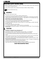
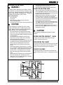
IMPORTANT SAFETY INSTRUCTIONS
This machine is only suitable for commercial use, for example in hotels, schools, hospitals, factories, shops and offices other
than normal residential housekeeping purposes.
When using an electrical appliance, basic precautions should always be followed, including the following:
Read all instructions before using.
WARNING!
To reduce risk of fire, electric shock, or injury:
•This machine should only be used by properly trained and authorized persons.
•Keep sparks, flame and smoking materials away from batteries. Explosive gases are vented during normal operation.
•Charging the batteries produces highly explosive hydrogen gas. Charge batteries only in well-ventilated areas, away
from open flame. Do not smoke while charging the batteries.
•Remove all jewelry when working near electrical components.
•Turn the key switch off (O) and disconnect the batteries before servicing electrical components.
•Never work under a machine without safety blocks or stands to support the machine.
•Do not dispense flammable cleaning agents, operate the machine on or near these agents, or operate in areas where
flammable liquids exist.
•Do not clean this machine with a pressure washer.
•Do not operate this machine on ramps or inclines of more than a 2 percent gradient.
•Only use the brushes provided with the appliance or those specified in the instruction manual. The use of other brushes
may impair safety.
CAUTION!
•This machine is not approved for use on public paths or roads.
•This machine is not suitable for picking up hazardous dust.
•When operating this machine, ensure that third parties, particularly children, are not endangered.
•Before performing any service function, carefully read all instructions pertaining to that function.
•Do not leave the machine unattended without first turning the key switch off (O), removing the key and securing the
machine.
•Turn the key switch off (O) and remove the key, before changing the brushes, and before opening any access panels.
•Take precautions to prevent hair, jewelry, or loose clothing from becoming caught in moving parts.
•Use caution when moving this machine in below freezing temperature conditions. Any water in the solution or recovery
tanks or in the hose lines could freeze.
•The batteries must be removed from the machine before the machine is scrapped. The disposal of the batteries should
be safely done in accordance with your local environmental regulations.
•Do not use on surfaces having a gradient exceeding that marked on the machine.
•All doors and covers are to be positioned as indicated in the instruction manual before using the machine.
SAVE THESE INSTRUCTIONS

FORM NO. 56041551 - AquaMAX™ / AX 650 - 55
55
5
ENGLISH 5ENGLISH 5
ENGLISH 5ENGLISH 5
ENGLISH 5
CONSIGNES DE SECURITE IMPORTANTES
Cette machine est destinée à un usage commercial et peut, entre autres, être utilisée dans les hôtels, écoles,
hôpitaux, usines, magasins et bureaux. Elle n’a donc pas été conçue pour l’entretien ménager.
Lorsque vous utilisez un appareil électrique, il y a certaines règles de base que vous devez toujours observer, dont
celle énoncée ci-après.
Lire toutes les instructions avant d’utiliser l’appareil.
ATTENTION!
Afin de réduire les risques d’incendie, de décharge électrique ou de blessure :
•Cette machine ne pourra être utilisée que par du personnel parfaitement entraîné et dûment autorisé.
•Eloignez les batteries de toutes flammes, étincelles ou substance fumigène. Les gaz explosifs sont ventilés pendant le
fonctionnement normal.
•De plus, du gaz hydrogène explosif s’échappe des batteries lorsqu’elles sont en charge. Ne procédez au chargement
des batteries que dans une zone bien ventilée, loin de toute flamme. Ne fumez pas à proximité des batteries lorsqu’elles
sont en charge.
•Otez tous vos bijoux lorsque vous travaillez à proximité de composants électriques.
•Positionnez la clé de contact sur off (O) et déconnectez les batteries avant de procéder à l’entretien des composants
électriques.
•Ne travaillez jamais sous une machine sans y avoir placé, au préalable, des blocs de sécurité ou des étais destinés à
soutenir la machine.
•Ne déversez pas d’agents nettoyants inflammables, ne faites pas fonctionner la machine à proximité de ces agents ou
d’autres liquides inflammables.
•Ne nettoyez pas cette machine avec un nettoyeur à pression.
•Ne faites pas fonctionner la machine sur des rampes ou pentes de plus de 2 pour-cent.
•Utilisez uniquement les brosses fournies avec l’appareil ou celles spécifiées dans le manuel d’instructions. L’utilisation
d’autres brosses peut mettre la sécurité en péril.
PRUDENCE!
•Cette machine n’est pas conçue pour une utilisation sur les chemins ou voies publics.
•Cette machine n’est pas conçue pour le ramassage des poussières dangereuses.
•Lors de l’utilisation de cette machine, assurez-vous que des tiers, et notamment des enfants, ne courent pas le moindre
risque.
•Avant de procéder à toute opération d’entretien, veuillez lire attentivement toutes les instructions qui s’y rapportent.
•Ne laissez pas la machine sans surveillance sans avoir, au préalable, coupé le contact, enlevé la clé de contact (O) et
tiré le frein à main.
•Positionnez la clé de contact sur off (O) avant de remplacer les brosses ou d’ouvrir tout panneau d’accès.
•Prenez toutes les mesures nécessaires pour éviter que les cheveux, les bijoux ou les vêtements amples ne soient
entraînés dans les parties mobiles de la machine.
•Faites attention lorsque vous déplacez cette machine dans un endroit où la température peut descendre sous 0°. Car
l’eau contenue dans la solution, dans les réservoirs de récupération ou dans les conduites risquerait de geler.
•Prenez soin d’enlever les batteries de la machine avant de mettre cette dernière au rebut. Pour ce qui est de
l’élimination des batteries, conformez-vous aux réglementations locales en matière d’environnement.
•N’utilisez pas sur des surfaces dont la pente dépasse celle mentionnée sur la machine.
•Toutes les portes et couvercles doivent être dans la position mentionnée dans le manuel d’instruction avant de mettre la
machine en service.
CONSERVEZ SOIGNEUSEMENT CES INSTRUCTIONS

6 6
6 6
6 - FORM NO. 56041551 - AquaMAX™ / AX 650
6 ENGLISH6 ENGLISH
6 ENGLISH6 ENGLISH
6 ENGLISH
1
23
456
78
910
11
12
14
18
19
15
17
20
21
22
25
24
23
26
27
13
16
18
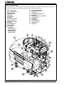
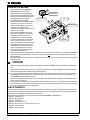
KNOW YOUR MACHINE
As you read this manual, you will occasionally run across a bold number in parentheses - example: (2). These numbers refer to an item on this
page. Refer back to this page whenever necessary to pinpoint the location of an item mentioned in the text.
1 Upper (recovery) Tank
2 Recovery Tank Dome Lid
3 Battery Fuel Gauge
4 Master Key Switch
5 Pump Switch
6 Vacuum Switch
7 Hour Meter
8 Brush Pressure Indicator
9 Speed Control Knob
10 Operator Control Handle
11 Drive Paddle
12 Brush Deck Lift Lever
13 Upper Tank Latch
14 Accessory Port
15 Circuit Breakers
6 Amp-Control Circuit
40 Amp-Vac Motors
20 Amp-Brush Motor
20 Amp-Drive Motor
16 Battery Charger Connector
17 Recovery Tank Drain Hose
18 Pick-Up Tool
19 Brush Height Adjustment Knob
20 Brush Deck
21 Solution Drain Hose / Level Indicator
22 Solution Fill Cap
23 Vacuum Hose
24 Recovery Hose
25 Nozzle Selector Knob
26 Stabilizer Caster
27 Rear Caster

FORM NO. 56041551 - AquaMAX™ / AX 650 - 77
77
7
ENGLISH 7ENGLISH 7
ENGLISH 7ENGLISH 7
ENGLISH 7
36
28
30
29
31
34
38
32
33
37
35
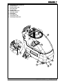
28 Lower (solution) Tank Flush-Out Cap
29 Brush Access Door
30 Brush Access Door Latch
31 Deck Release Knob
32 Vac Motor Filters
33 Automatic Float Shut-Off
34 Waste Water Bladder
35 Roller Bumper
36 InLine Pump Filter
37 Lower (solution) Tank
38 Roller Bumper Release Knob

8 8
8 8
8 - FORM NO. 56041551 - AquaMAX™ / AX 650
8 ENGLISH8 ENGLISH
8 ENGLISH8 ENGLISH
8 ENGLISH
FUNCTIONAL DESCRIPTION OF CONTROLS:
Upper (recovery) Tank (1) - Waste water recovered from carpet is deposited here inside of a bladder (34). Area outside of waste water bladder (34) is utilized for
extra clean solution capacity. The batteries and Vac Motor Filters (32) can be accessed by opening this tank to the side.
Recovery Tank Dome Lid (2) - Point of entry for waste water into bladder. Also houses Automatic Float Shut-Off (33) which shuts off vacuum port to vac motors
when bladder is full. Remove this lid to rinse out the waste water bladder or to fill the solution tank.
Battery Fuel Gauge (3) - Shows current state of charge of batteries. A double-flashing light indicates low batteries, charge immediately. NOTE: When the battery
fuel gauge shows double-flashing lights, all systems shut down except the wheel drive system.
Master Key Switch (4) - Main power switch.
Pump Switch (5) - This button is used to select the mode of operation for the solution system. There are 3 modes of operation for this system. The modes are
AUTO / OFF / ON. Following is a description of each mode.
AUTO MODE: In this mode the solution flow will be turned ON whenever the brush is lowered and the machine is moving forward. The solution flow will be turned
off when the machine is not moving, moving in reverse or the brush is raised.
OFF MODE: In this mode the solution flow is turned off.
ON MODE: This mode is for accessory use. The pump is ON at all times as long as the Master Key Switch (4) is ON.
Vacuum Switch (6) - This button is used to select the mode of operation for the vacuum system. There are 3 modes of operation for this system. These modes are
AUTO / OFF / ON. Following is a description of each mode.
AUTO MODE: In this mode the vacuum will be turned ON whenever the brush is lowered and the Master Key Switch (4) is ON. While in this mode the vacuum will
remain on for 10 seconds after the brush is raised.
OFF MODE: In this mode the vacuum is off.
ON MODE: This mode is for accessory use. The vacuum is ON at all times as long as the Master Key Switch (4) is ON.
Hourmeter (7) - Displays number of hours machine has been used. NOTE: The hourmeter only runs when the vac motors are running.
Brush Pressure Indicator (8) - This meter should be reading 8-15 amps (green zone), readings outside this range indicate the need for brush height adjustment.
Speed Control Knob (9) - Turn this knob clockwise to increase maximum speed range and counter-clockwise to decrease maximum speed range.
Operator Control Handle (10) - Operator holds onto this handle to maneuver the machine.
Drive Paddle (11) - The operator can make the machine go forward by pushing forward on it, or reverse by pulling backward on it. The speed is variable
depending on how far forward or backward the paddle is moved. The brush and pump will operate when the brush deck is in the “DOWN” position and the drive
paddle is engaged in either direction, both will stop 1 second after the drive paddle is released. NOTE: The pump does not run when the drive paddle is in the
reverse position.
Brush Deck Lift Lever (12) - This lever is used to raise or lower the brush deck. Both pump and vacuum turn ON when the brush deck is lowered and turn OFF
when it is raised if their switches are in the AUTO position. NOTE: Machine must be moving forward to activate pump, forward or reverse to activate brush.
Vacuum system shuts off 10 seconds after raising the brush deck.
Upper Tank Latch (13) - This latch is used to secure the Upper Tank (1) to the machine to prevent the tank from opening while operating the machine since the
Operator Control Handle (10) is mounted to the upper tank.
Accessory Port (14) - This is used to connect external accessories.
Circuit Breakers (15)
6 Amp-Control Circuit - Provides overload protection. If it trips, it will pop out. To reset, wait one minute and press the button back in. If any breaker trips
repeatedly, have the machine serviced.
40 Amp-Vac Motors - Provides overload protection to machine’s vacuum motors. If it trips, it will pop out. To reset, wait one minute and press the button back
in. If any breaker trips repeatedly, have the machine serviced.
20 Amp-Brush Motor - Provides overload protection to machine’s brush motor. If it trips, it will pop out. To reset, wait one minute and press the button back in.
If any breaker trips repeatedly, have the machine serviced.
20 Amp-Drive Motor - Provides overload protection to machine’s wheel drive motor. If it trips, it will pop out. To reset, wait one minute and press the button
back in. If any breaker trips repeatedly, have the machine serviced.
Battery Charger Connector (16) - Plug battery charger into this port to charge batteries.
Recovery Tank Drain Hose (17) - Used to empty the recovery tank. NOTE: Hold the end of the hose above the water level in the tank to avoid sudden, uncon-
trolled flow of waste water when removing plug.
Pick-Up Tool (18) - Removes excess solution from carpet after scrubbing.
Brush Height Adjustment Knob (19) - Used to adjust the height of the brush deck. Turn clockwise to raise the brush deck and counter-clockwise to lower the
brush deck. NOTE: Use this adjustment knob in conjunction with the Brush Pressure Indicator (8).
Brush Deck (20) - Contains brush drive motor and brush.
Solution Drain Hose/Level Indicator (21) - Used to empty the solution tank and show current level of solution in tank, graduations are marked on the side of the
machine next to the hose.
Solution Fill Cap (22) - The solution tank can be filled at this location or through the front opening at the top of the Upper Tank after removing the Recovery Tank
Dome Lid.
Vacuum Hose (23) - This hose connects to the vac motor assembly in order to create a vacuum inside the waste water bladder.
Recovery Hose (24) - This hose connects between the Pick-Up Tools (18) and the Recovery Tank Dome Lid (2) to bring waste water into the bladder.
Nozzle Selector Knob (25) - Use this knob to select either Maintenance Mode or Restoration Mode. NOTE: The Speed Control Knob (9) has two corresponding
settings.
Maintenance Mode: Lower solution flow, higher travel speed. Recommended for frequent surface cleaning.
Restoration Mode: Higher solution flow, lower travel speed. Recommended for less frequent deep cleaning.
Stabilizer Caster (26) - This caster provides stability to the unit when opening the Upper (recovery) Tank (1).
Rear Caster (27) - These two casters along with the main drive wheel bear the weight of the machine and allow easy maneuvering around corners.
Lower (solution) Tank Flush-Out Cap (28) - This cap allows access to the Lower (solution) Tank for the purpose of flushing with clean water.
Brush Access Door (29) - The power brush can be removed or installed via this door.
Brush Access Door Latch (30) - Unsnap this latch to allow access to the power brush.
Deck Release Knob (31) - Pull this knob out and slide Brush Deck out to the right until it latches in place. This allows cleaning under shelves, railings, etc.
Vac Motor Filters (32) - Intake filters for vacuum motor assembly. Refer to the maintenance chart for maintenance intervals.
Automatic Float Shut-Off (33) - The float shut-off blocks the vacuum port when the Waste Water Bladder (34) is full. You can tell when the float closes by the
sudden change in sound of the vacuum motors. When the float closes, the recovery tank must be emptied. The machine will not pickup water with the float closed.
Waste Water Bladder (34) - Contains waste water as it is recovered from carpet. Total capacity of 30 gallons (113.5 Liters).
Roller Bumper (35) - This is a 3 position slide-out bumper to aid in machine maneuvering along walls.
InLine Pump Filter (36) - This filter removes debris from the solution prior to flowing through the pump. Drain solution prior to cleaning this filter.
Lower (solution) Tank (37) - This tank in combination with the upper tank brings total solution capacity to 40 gallons (151.4 Liters).
Roller Bumper Release Knob (38) - This knob allows you to slide the roller bumper out or in to limit how close the machine travels to the wall.

FORM NO. 56041551 - AquaMAX™ / AX 650 - 9- 9
- 9- 9
- 9
ENGLISH 9ENGLISH 9
ENGLISH 9ENGLISH 9
ENGLISH 9
FRONT
INSTALLING THE BATTERIES
WARNING!
Use extreme caution when working with batteries. Sulfuric
acid in batteries can cause severe injury if allowed to contact
the skin or eyes. Explosive hydrogen gas is vented from the
batteries through openings in the battery caps. This gas can
be ignited by any electrical arc, spark or flame.
When Servicing Batteries...
*Remove all jewelry
*Do not smoke
*Wear safety glasses, rubber gloves and a rubber apron
*Work in a well-ventilated area
*Do not allow tools to touch more than one battery terminal at a time
CAUTION!
Electrical components in this machine can be severely
damaged if the batteries are not installed and connected
properly. Batteries should be installed by Nilfisk-Advance, a
qualified electrician, or the battery manufacturer.
1Remove the batteries from their shipping crate and carefully
inspect them for cracks or other damage. If damage is evident,
contact the carrier that delivered them or the battery manufacturer
to file a damage claim.
2Turn the Master Key Switch (4) OFF and remove the key.
3Open the Upper (recovery) Tank (1). Remove the battery
cables from inside the battery compartment.
4Your machine comes from the factory with enough battery cables
to install six 6 volt batteries. Carefully lift the batteries into the
battery compartment and arrange them exactly as shown.
Secure the batteries as close to the back of the machine as
possible.
5The terminals on the battery cables are marked “+” for positive
and “–” for negative. Install the battery cables as shown, with the
terminals marked “+” on the positive battery terminals and the
terminals marked “–” on the negative terminals. Position the
cables so the battery caps can be easily removed for battery
service.
6Carefully tighten the nut in each battery terminal until the terminal
will not turn on the battery post. Then tighten the nut one
additional turn. Do not over-tighten the terminals, or they will be
very difficult to remove for future service.
7Coat the terminals and posts with spray-on battery terminal
coating (available at most auto parts stores).
8Put one of the black rubber boots over each of the terminals.
FILLING THE SOLUTION TANK
1Either remove the Solution Fill Cap (22) or the Recovery Tank
Dome Lid (2). NOTE: When filling the solution tank via the top of
the Upper Tank (1), make sure that you pour the solution into the
opening closest to the front of the machine.
2Read the dilution instructions on the chemical container. Then
figure the proper amount of chemical to mix with 40 gallons
(151.41 liters) of water. For best results, use the Nilfisk-Advance
CarpeTeam™ Extraction Cleaner chemical specially formulated
for use with Nilfisk-Advance carpet extractors.
3Pour the chemical into the solution tank and fill the tank with warm
water. NOTE: Watch the Solution Level Indicator (21) as you fill
the tank. When it reaches the 40 gallon mark, stop.
4Put the Solution Filler Cap (22) or the Recovery Tank Dome Lid
(2) back on the machine. NOTE: Make sure the Dome Lid is
properly seated on the tank.
CAUTION!
Use low-sudsing, liquid detergents designed for carpet
extraction.
BEFORE USING THE AQUAMAX™ / AX 650
Thoroughly vacuum the carpet to be cleaned before using the
AquaMAX™ / AX 650 automatic extractor.
PRE-SPRAYING THE CARPET
Pre-spray spots and heavy traffic areas before extracting. Use a hand-
held bottle sprayer or a pressurized “Hudson” type sprayer. Mix the
pre-spray according to the chemical manufacturer’s directions.
PLAN FOR CLEANING
Before you begin extracting, look at the area to be cleaned and plan
your work. Divide the space into sections. Overlap each pass 2 inches
(5 cm).

10 10
10 10
10 - FORM NO. 56041551 - AquaMAX™ / AX 650
10 ENGLISH10 ENGLISH
10 ENGLISH10 ENGLISH
10 ENGLISH
56
Auto
9
25
Restoration
Maintenance
Restoration
Maintenance
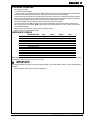
OPERATING THE MACHINE
1Follow the instructions in the Preparing the
Machine for Use section of this manual.
2Make sure the Solution Fill Cap (22) and the
Recovery Tank Dome Lid (2) are firmly in place.
3Make sure the Pump Switch (5) and the Vacuum
Switch (6) are both in the AUTO position.
4Turn the Master Key Switch (4) ON.
5Adjust the Nozzle Selector Knob (25) to either the
“maintenance” or “restoration” mode. Set the
Speed Control Knob (9) to the corresponding
“maintenance” or “restoration” setting.
6Lower the Brush Deck (20) to the floor using the
Brush Deck Lift Lever (12).
7When the Drive Paddle (11) is in the neutral
position, the brush does not run and solution is
not dispensed. Grip the Operator Control
Handle (10) and push the Drive Paddle (11)
forward to start the brush motor and the solution,
and to move the machine forward. For best
results, move the machine at full speed assuming
that step 5 has been completed. Pull the Drive
Paddle (11) backward to move the machine in
reverse. The brush will turn in the opposite
direction while moving the machine in reverse,
and solution will not be dispensed.
8Begin cleaning by driving the machine forward in a straight line and overlap each pass by 2 inches (5 cm). Turn the Pump Switch (5) OFF
prior to turns to ensure complete extraction of solution from carpet. Guide the right side of the machine along the wall when cleaning the
perimeter of the room.
9Watch the fluid entering the Recovery Tank Dome Lid (2). If there is a large amount of suds in the recovery tank, add a defoamer chemical
to the recovery tank.
CAUTION!
Empty the recovery tank before the fluid or foam enters the Vacuum Hose (23) at the rear of the Recovery Tank Dome
Lid.
If there is little or no fluid entering the recovery tank, check the Solution Drain Hose / Level Indicator (21), the solution tank may be empty.
Refill the solution tank with water and the proper ratio of cleaning chemical.
10 The recovery tank has an Automatic Float Shut-Off (33) to block the vacuum system when the recovery tank is full. You can tell when the
float closes by the sudden change in the sound of the vacuum motors. When the float closes, the recovery tank must be emptied. The
machine will not pick up water with the float closed.
11 When the operator wants to stop cleaning or the recovery tank is full, raise the Brush Deck Lift Lever (12). This will automatically stop the
brush, pump and vacuum motors.
12 Drive the machine to a designated waste water “DISPOSAL SITE” and empty the recovery tank. To empty, pull the Drain Hose (17) from
it’s rear storage area, then remove the plug (hold the end of the hose above the water level in the tank to avoid sudden, uncontrolled flow of
waste water). Refill the solution tank and continue cleaning.
USING ATTACHMENTS
To use accessory tools, attach the accessory recovery hose to the front port of the Recovery Tank Dome Lid (2). Attach the accessory solution
hose to the Accessory Port (14). Connect the other ends of the hoses to the accessory tool. When using accessory tools, raise the Brush Deck
(20) and place the Pump (5) and Vacuum (6) Switches in the ON position.
See your Nilfisk-Advance Distributor for accessories that may be used with the AquaMAX™ / AX 650 including:
• 56250185 PowerHead™ 12
• 56204223 Drag Tool SS 4 Ft
• 56204224 Hand Tool SS
• 56249318 Scrub & Vac Hose 15 Ft
• 56801000 Aqua Kit (Includes PN 56800385, 56800390 & 56249318)
• 56800390 Drag Tool (Plastic)
• 56800385 Hand Tool (Plastic)

FORM NO. 56041551 - AquaMAX™ / AX 650 - 1111
1111
11
ENGLISH 11ENGLISH 11
ENGLISH 11ENGLISH 11
ENGLISH 11
AFTER USING THE MACHINE
1Raise the Brush Deck (12).
2Turn the Master Key Switch (4) OFF.
3To empty the solution tank, pull the Solution Drain Hose (21) off the elbow Direct the hose to a designated waste water “DISPOSAL SITE”
and remove the plug. Rinse the tank with clean water. Inspect the solution hoses; replace if kinked or damaged.
4To empty the recovery tank, take the Recovery Drain Hose (17) off its hanger. Direct the hose to a designated waste water “DISPOSAL
SITE” and remove the plug (hold the end of the hose above the water level in the tank to avoid sudden, uncontrolled flow of waste water).
Rinse the tank with clean water. Inspect the recovery and vacuum hoses; replace if kinked or damaged.
5Remove the Brush (29), rinse with warm water and remove any built-up string, hair or carpet fibers.
6Disconnect the Recovery Hose (24) from the Recovery Tank Dome Lid (2) and flush with warm water to wash any debris out of the
Recovery Hose / Pick-Up Tool Assembly. NOTE: Make sure that you have disconnected the correct hose, if you run water into the vac
motors they will be damaged.
7Wipe the machine with a damp cloth. Do not use abrasive chemicals or solvents.
8Perform any required maintenance before storage.
MAINTENANCE SCHEDULE
MAINTENANCE ITEM Daily Weekly Monthly Yearly
Charge Batteries •
Check / Clean Power Brush •
Check / Clean Tanks & Hoses •
Check / Clean Vacuum Shut-Off Float •
Check / Clean Vacuum Motor Filters •
Clean Pick-Up Tools •
Clean Spray Nozzles •
Check Each Battery Cell(s) Water Level •
Inspect Brush Deck Skirt •
Inspect & Clean InLine Pump Filter •
Lubricate the Machine •
*Check Carbon Brushes •
* Have a Nilfisk-Advance service technician check the vacuum motor carbon brushes once a year or after 300 operating hours. The brush and
drive motor carbon brushes check every 500 hours or once a year.
IMPORTANT!
Motor damage resulting from failure to service the carbon brushes is not covered under warranty. See the Limited Warranty
Statement.
9Store the machine in a clean, dry place with the tank dome lid open.

12 12
12 12
12 - FORM NO. 56041551 - AquaMAX™ / AX 650
12 ENGLISH12 ENGLISH
12 ENGLISH12 ENGLISH
12 ENGLISH
B
C
D
A
B
C
A
#
4
E
F
G
PICK-UP TOOL MAINTENANCE
Check the pick-up tools daily. Remove any built-up string, hair or carpet fibers.
SPRAY NOZZLE MAINTENANCE
Remove the spray nozzles once a week. Soak the nozzles overnight in a vinegar and water solution to remove chemical deposits.
LUBRICATING THE MACHINE
Once a month (or every 30 hours), lubricate all pivot points on the pick-up tool assembly. For best results, use a spray silicone lubricant.
Once a month, pump grease into the grease fittings on the caster wheels until it seeps out around the bearing. Wipe off the excess grease to avoid
staining carpet.
CLEANING THE VACUUM MOTOR FILTERS
Clean the vacuum motor filters daily with compressed air. For extremely dirty filters, wash with warm, soapy water and rinse thoroughly with clean
water. Allow the filters to dry completely before re-installing in the machine. MAINTENANCE NOTE: Keep a second set of filters on hand to use
while first set is drying.
ADJUSTING THE BRUSH HEIGHT
Simply turn the Brush Height Adjustment Knob (19) clockwise to raise and counter-clockwise to lower the brush deck. NOTE: The Brush Pressure
Indicator (8) should read 8-15 amps when properly adjusted.
POWER BRUSH MAINTENANCE
Check the brush daily. Remove any built-up string, hair or carpet fibers. Check the bristle length. Have a service technician change the brush
when the brush bristles are worn to 1/2 inch (12.7 mm).
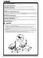
REMOVING THE BRUSH
CAUTION!
Turn the key switch off (O) and remove the key, before changing the brushes, and before opening any access panels.
1Turn the Master Key Switch OFF and raise the Brush Deck.
2See figure below. Unsnap Latch (A), remove Pin (B) and Brush Access Door (C). Slide the brush out of the brush deck housing.
3To reinstall, slide the brush under the brush deck housing, make sure the end with the large slots cut into it is inserted first.
4Reach under the left side of the brush deck to guide the end of the brush onto the drive lug (E). Push in and turn the brush until it is firmly
seated on the drive lug.
5 IMPORTANT! Make sure that the Bearing Block (D) is seated securely in the door and orientated as shown for “old style (F)”, “new style
(G)” machines have the bearing block attached to the access door. Hold the end of the brush up while re-installing Brush Access Door (C)
to ensure that the Bearing Block on the inside of the door is securely seated in the end of the brush.
6Re-install Pin (B) and re-secure Latch (A). Latch should secure easily. If it has to be forced, recheck the position of the brush.

FORM NO. 56041551 - AquaMAX™ / AX 650 - 1313
1313
13
ENGLISH 13ENGLISH 13
ENGLISH 13ENGLISH 13
ENGLISH 13
CHARGING THE BATTERIES
Charge the batteries when the Battery Fuel Gauge (3) shows a double flashing light.
WARNING!
Use extreme caution when working with batteries. Sulfuric acid in batteries
can cause severe injury if allowed to contact the skin or eyes. Explosive
hydrogen gas is vented from the batteries through openings in the battery
caps. This gas can be ignited by any electrical arc, spark or flame.
When Servicing Batteries...
*Remove all jewelry
*Do not smoke
*Wear safety glasses, rubber gloves and a rubber apron
*Work in a well-ventilated area
*Do not allow tools to touch more than one battery terminal at a time
Check the fluid level in each battery cell before charging. Add distilled water only until the water level is 1/4” above the plates. Push the connector
from the charger into the Battery Charger Connector (16) on the machine. Follow the instructions on the battery charger.
CAUTION!
To avoid damage to floor surfaces, wipe water and acid from the top of the batteries after charging.
CHECKING THE BATTERY WATER LEVEL
Check the water level of the batteries at least once a week.
After charging the batteries, remove the vent caps and check the water level in each battery cell. Use distilled or demineralized water in a battery
filling dispenser (available at most auto parts stores) to fill each cell to the level indicator (or to 10 mm over the top of the separators). DO NOT
over-fill the batteries!
CAUTION!
Acid can spill onto the floor if the batteries are overfilled.
Tighten the vent caps. Wash the tops of the batteries with a solution of baking soda and water (2 tablespoons of baking soda to 1 liter of water).
BATTERY MAINTENANCE
Proper maintenance of electric vehicle batteries can greatly extend their life. Well-maintained batteries may last up to 3 years, but failure after 1
year is common if maintenance has been poor.
There are 3 simple rules for good battery maintenance:
•Maintain Proper Electrolyte Level (Weekly) - Use distilled water in batteries whenever possible. If batteries are discharged, add just
enough water to cover the plates in each cell. If batteries are fully charged, fill each cell to the bottom of the filler tube. Do not over-fill the
batteries! Do not add acid to batteries!
•Keep the Batteries Charged (Weekly) - Batteries should be charged each time that a machine is used for more than 1 hour. Machine
operators should open the battery compartment cover for charging, to avoid a concentrated build-up of hydrogen gas. Even when a
machine is stored, the batteries should be charged once a month to prevent the batteries from “sulfating”. Almost all battery caps are vented,
so there’s no need to loosen or remove them for charging.
•Keep the Batteries Clean (Monthly) - Use a damp cloth to wipe dirt from the top of the batteries. Battery terminals must be clean and tight.
If the tops of the batteries are wet after charging, the batteries have probably been over-filled or over-charged. Note: If there is acid on the
batteries, wash the tops of the batteries with a solution of baking soda and water (2) tablespoons of baking soda to 1 quart of water.
BATTERY TESTING
A battery problem is usually recognized by the machine operator, as a decrease in the machine’s running time. This condition is usually caused by
one (or more) “dead cell” in the battery system- that is, one (or more) cell that is putting out less voltage than the other cells.
Note: Always charge batteries before testing.
There are 2 ways to find a dead cell:
• Use a hydrometer to check the specific gravity (or “state of charge”) of the fluid in each cell. A dead cell is one that reads 50 points (or more)
lower than the other cells.
• Use a volt meter to check the voltage of each battery with the brush motor running. The battery with the dead cell will read 1 or 2 volts lower
than the other batteries in the system.
If the batteries in the machine are more than 1 year old, it’s usually best to replace the whole set, rather than replacing just one battery.

14 14
14 14
14 - FORM NO. 56041551 - AquaMAX™ / AX 650
14 ENGLISH14 ENGLISH
14 ENGLISH14 ENGLISH
14 ENGLISH
6 AMP CONTROL CIRCUIT CIRCUIT BREAKER
When the Control Circuit Circuit Breaker (15) trips, push the button to reset the circuit breaker.
If the circuit breaker trips repeatedly, call your local Nilfisk-Advance Distributor for service.
20 AMP WHEEL DRIVE CIRCUIT BREAKER
When the Wheel Drive Circuit Breaker (15) trips, check to see if there is debris wrapped around the wheel axle. Remove the debris from the axle.
Have the wheel drive motor checked for worn out brushes; repair or replace the motor if necessary. Push the button to reset the circuit breaker.
If the circuit breaker trips repeatedly, call your local Nilfisk-Advance Distributor for service.
20 AMP BRUSH DRIVE CIRCUIT BREAKER
When the Brush Drive Circuit Breaker (15) trips, check to see if the brush height is set too low or if there is debris wrapped around the brush.
Adjust the brush height or remove the debris from the brush. Push the button to reset the circuit breaker.
If the circuit breaker trips repeatedly, call your local Nilfisk-Advance Distributor for service.
40 AMP VACUUM MOTOR CIRCUIT BREAKER
When the Vacuum Motor Circuit Breaker (15) trips, check the Vac Motor Filters (32) and clean or replace if necessary. Have the vacuum motors
checked for worn out bearings and/or brushes or bearing failure. Repair or replace the motors if necessary. Push the button to reset the circuit
breaker.
If the circuit breaker trips repeatedly, call your local Nilfisk-Advance Distributor for service.
TECHNICAL SPECIFICATIONS (as installed and tested on the unit)
Model AquaMAX™ / AX 650
Model No. 56212000 / 56212260
Voltage, batteries V 36V
Battery capacity Ah 238
Protection grade IPX3
Sound power level as per ISO 3744 (at operator) dB(A)/20µPa 76
Gross weight (with acc. and batteries, full tank) lbs / kg 1,171 / 531
Vibrations at the Hand Controls m/s2<2,5m/s2


©Nilfisk-Advance Inc., F00018, 1/03
.pas
_____________________________________________________
TYPE: AX 650
EU Overensstemmelseserklæring DK Déclaration CE de conformité B, F
Tæpperensemaskine Injecteur- extracteur
Maskinen er fremstillet i overensstemmelse med følgende
direktiver:
Cette machine a été fabriquée conformément aux directives
suivantes:
Maskindirektiv: 98/37/EØF Réglementation machine: 98/37/CEE
EMC-direktiv: 89/336/EØF 92/31/EØF 93/68/EØF 98/13/EOF Réglementation CEM:
89/336/CEE,92/31/CEE,93/68/CEE,98/13/CEE
Lavspændingsdirektiv: 73/23/EØF 93/68/EØF
Harmoniserede standarder: EN 60 335-2-72
Règlement basse tension: 73/23/CEE 93/68/CEE
Normes harmonisées: EN 60 335-2-72
EU Överensstämmelseförsäkran S, FIN EG-conformiteitsverklaring NL, B
Golvvårdsmaskin Sproei-extractie machine
Maskinen är tillverkad i överensstämmelse med följande
direktiver:
Deze machine is vervaardigd overeenkomstig de volgende
richtlijnen:
Maskindirektiv: 98/37/EEG Machine richtlijn: 98/37/EEC
EMC-direktiv: 89/336/EEG 92/31/EEG 93/68/EEG 98/13/EEG EMC-richtlijn: 89/336/EEC 92/31/EEC 93/68/EEC 98/13/EEC
Lågspänningsdirektiv: 73/23/EEG 93/68/EEG
Harmoniserade standarder: EN 60 335-2-72
Laagspanning richtlijn: 73/23/EEC 93/68/EEC
Geharmoniseerde normen: EN 60 335-2-72
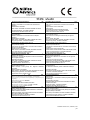
EU Declaration of Conformity GB, IRL Declaración de conformidad de la CEE E
Spray extraction machine Máquina inyección/extracción
This machine was manufactured in conformity with the following
directives and standards:
Esta máquina ha sido fabricada en conformidad a las siguientes
normativas:
Machine Directive: 98/37/EEC Normativa de la máquina: 98/37/CEE
EMC-directive: 89/336/EEC 92/31/EEC 93/68/EEC 98/13/EEC Normativa EMC: 89/336/CEE 92/31/CEE 93/68/CEE 98/13/CEE
Low voltage directive: 73/23/EEC 93/68/EEC
Harmonized standards: EN 60 335-2-72
Normativa sobre baja tensión: 73/23/CEE 93/68/CEE
Normas armonizadas: EN 60 335-2-72
Dichiarazione di conformità - CEE I EU Declaração de conformidade da CE P
Macchina ad estrazione Máquina de injecção/extrcção
È prodotto in conformità alle disposizioni contenute nelle Direttive
del Consiglio dei Ministri:
Esta máquina foi fabricada em conformidae com as seguintes
directrizes:
M-direttiva: 98/37/EEC Directriz de maquinaria: 98/37/CEE
EMC-direttiva: 89/336/EEC 92/31/EEC 93/68/EEC 98/13/EEC Directriz EMC: 89/336/CEE 92/31/EEC 93/68/CEE 98/13/CEE
LV-direttiva: 73/23/EEC 93/68/EEC
Norme armonizzate: EN 60 335-2-72
Directriz de baixa voltagem: 73/23/CEE 93/68/CEE
Normas harmonizadas: EN 60 335-2-72
EG – Konformitätserklärung D, A EU:n yhdenmukaisuudesta direktiiveihin FIN
Sprühextraktionsmaschine Painehuuhtelukone
Diese Maschine wurde gemäβ den folgenden Richtlinien
hergestellt:
On valmistettu noudattaen yhteisön määräämiä direktiivejä:
Maschinerichtlinie: 98/37/EWG M-direktiivi: 98/37/CEE
EMV-Richtlinie: 89/336/EWG 92/31/EWG 93/68/EWG 98/13/EWG EMC-direktiivi: 89/336/CEE 92/31/CEE 93/68/CEE 98/13/CEE
Niederspannungsrichtlinie: 73/23/EWG 93/68/EWG
Harmonisierte normen: EN 60 335-2-72
LV-direktiivi: 73/23/CEE 93/68/CEE
Yhdenmukaistetut standardit: EN 60 335-2-72
Δηλωσηπροσαρμογης/συóρϕωσης EU GR EL vastavusdeklaratsioon ET
Μηχανημα καθαρισμου χαλιων ψεκασμου−αναρρóϕησης Pihustusmasin
Το μηχανημα ιχει καταοκευαοτει ονμψωϖα με τις παρακατω προσ
ιαγραψες:
Käesolev masin on valmistatud kooskõlas järgmiste direktiivide ja
standarditega:
Προσιαγραωη μηχανηματος: 98/37/EEC Masinadirektiiv: 98/37/EEC
Προσιαραψη−EMC:
89/336/EEC,92/31/EEC,93/68/EEC,98/13/EEC
Elektromagnetilise sobivuse direktiiv: 89/336/EEC 92/31/EEC
93/68/EEC 98/13/EEC
Προσιαγραψη χαμηλης ταοεως: 73/23/EEC 93/68/EEC Madalpinge direktiiv: 73/23/EEC 93/68/EEC
Εναρμονισμενα προτυπα: EN 60 335-2-72 Ühtlustatud standardid: EN 60 335-2-72
ES atbilstības deklarācija LV Pareiškimas apie atitikimą ES direktyvoms LT
Šļakatu ekstrakcijas mašīna Skysčio surinkimo mašina
Šī mašīna izgatavota atbilstoši šādām direktīvām un standartiem: Šis įrenginys pagamintas laikantis tokių direktyvų bei standartų:
Mašīnu direktīva: 98/37/EEC Įrengimų direktyva: 98/37/EEC
Elektromagnētiskās savietojamības (EMC) direktīva: 89/336/EEC
92/31/EEC 93/68/EEC 98/13/EEC EMC direktyva: 89/336/EEC 92/31/EEC 93/68/EEC 98/13/EEC
Zemsprieguma direktīva: 73/23/EEC 93/68/EEC
Saskaņotie standarti: EN 60 335-2-72
Žemos įtampos įrengimų direktyva: 73/23/EEC 93/68/EEC
Harmonizuoti standartai: EN 60 335-2-72

©Nilfisk-Advance Inc., F00018, 1/03
.pas
Deklaracija EU o skladnosti SL Prehlásenie o súlade EÚ SK
Stroj za razprševanje čistila Zariadenie na odsávanie povrchového postreku
Ta stroj je izdelan v skladu z naslednjimi smernicami in standardi: Toto zariadenie bolo vyrobené v súlade s nasledujúcimi
direktívami a normami:
Smernica o strojih: 98/37/EEC Direktíva o zariadeniach: 98/37/EEC
Smernica o elektromagnetni združljivosti (EMC): 89/336/EEC
92/31/EEC 93/68/EEC 98/13/EEC Direktíva EMC: 89/336/EEC 92/31/EEC 93/68/EEC 98/13/EEC
Smernica o nizki napetosti: 73/23/EEC 93/68/EEC
Harmonizirani standardi: EN 60 335-2-72 Direktíva o nízkom napätí: 73/23/EEC 93/68/EEC
Súvisiace normy: EN 60 335-2-72
EU Prohlášení o shodě CS Deklaracja zgodności z normami UE PL
Odsávací stroj Urządzenie do wysokociśnieniowego prania dywanów
Tento stroj byl vyroben ve shodě s následujícími směrnicemi a normami: Niniejsze urządzenie zostało wyprodukowane w zgodzie z
następującymi dyrektywami i normami UE:
Směrnice o strojním zařízení: 98/37/EEC Dyrektywa dotycząca maszyn: 98/37/EEC
Směrnice o elektromagnetické kompatibilitě: 89/336/EEC 92/31/EEC
93/68/EEC 98/13/EEC
Dyrektywa: kompatybilność elektromagnetyczna 89/336/EEC
92/31/EEC 93/68/EEC 98/13/EEC
Směrnice o nízkém napětí: 73/23/EEC 93/68/EEC
Harmonizované normy: EN 60 335-2-72
Dyrektywa: urządzenia elektromagnetyczne niskonapięciowe
73/23/EEC 93/68/EEC
Zharmonizowane normy: EN 60 335-2-72
EU megfelelőségi nyilatkozat HU Декларация изготовителя о соответствии директивам ЕС
Permetfelszívógép Распылительный пылесос
Ez a gép az alábbi irányelvekkel és szabványokkal összhangban
készült:
Данная машина разработана в соответствии со следующими
инструкциями и стандартами:
Gépészeti irányelvek 98/37/EEC Инструкция по разработке машин: 98/37/EEC
EMC-irányelvek 89/336/EEC 92/31/EEC 93/68/EEC 98/13/EEC Инструкция EMC: 89/336/EEC 92/31/EEC 93/68/EEC 98/13/EEC
Kisfeszültségű irányelvek: 73/23/EEC 93/68/EEC
Harmonizált szabványok: EN 60 335-2-72
Инструкция по использованию низких напряжений: 73/23/EEC
93/68/EEC
Согласованные стандарты: EN 60 335-2-72
EU Uygunluk Beyanı TK
Bataryayla çalışan zemin fırçalama sistemi .
Bu makine aşağıdaki direktiflere ve standartlara uygun olarak
üretilmiştir.
Makine Direktifi : 98/37/EEC
EMC Direktifi : 89/336/EEC 92/31/EEC 93/68/EEC 98/13/EEC
Düşük voltaj Direktifi : 73/23/EEC 93/68/EEC
Uyumlu standartlar :EN 60 335-2-72
4.4.2004 .
Larry Doerr, Vice President Operations
Nilfisk-Advance, Inc. Nilfisk-Advance A/S
14600 21st Avenue North Sognevej 25
Plymouth, MN 55447 USA DK-2605 Brøndby, Denmark

www.nilfi sk-advance.com © 2006
-
 1
1
-
 2
2
-
 3
3
-
 4
4
-
 5
5
-
 6
6
-
 7
7
-
 8
8
-
 9
9
-
 10
10
-
 11
11
-
 12
12
-
 13
13
-
 14
14
-
 15
15
-
 16
16
-
 17
17
-
 18
18
-
 19
19
-
 20
20


Nilfisk-Advance 56212260 Manuel utilisateur
- Catégorie
- Machine à plancher
- Taper
- Manuel utilisateur
- Ce manuel convient également à
dans d''autres langues
- italiano: Nilfisk-Advance 56212260 Manuale utente
- English: Nilfisk-Advance 56212260 User manual