
System
Heat Pump Indoor Unit
INSTALLATION MANUAL
LG
MODELS: SE/S5 Series
Type: Wall Mounted
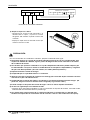
IMPORTANT
• Please read this installation manual completely before
installing the product.
• Installation work must be performed in accordance with
the national wiring standards by authorized personnel
only.
• Please retain this installation manual for future reference
after reading it thoroughly.
ENGLISH ITALIANO ESPAÑOL FRANÇAIS DEUTSCH

2 Indoor Unit
Wall Mounted Type Indoor Unit Installation Manual
TABLE OF CONTENTS
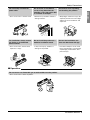
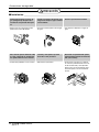
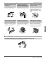
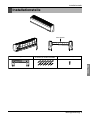
❏ Installation guide map
❏ Four type "A" screws & plastic
anchors
❏ Connecting cable
❏ Pipes: Gas side
Liquid side
(Refer to Product Data)
❏ Insulation materials
❏ Additional drain pipe
❏ Twotype"B"screws
❏ Level gauge
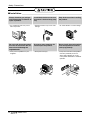
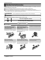
❏ Screw driver
❏ Electric drill
❏ Hole core drill
❏ Horizontal meter
❏ Flaring tool set
❏ Specified torque wrenches
(different depending on model No.)
❏ Spanner .......Half union
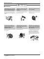
❏ A glass of water
❏ Screw driver
❏ Hexagonal wrench
❏ Gas-leak detector
❏ Vacuum pump
❏ Gauge manifold
❏ Owner's manual
❏ Thermometer
❏ Holder Remote Controller
Installation Parts ....................3
Safety Precautions .................4
Installation
Selection the best location ....7
Piping Method........................8
Drain Piping .........................13
Wiring Connection ...............13
Installation of Remote
Controller..............................15
Installation Requirements
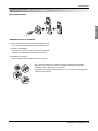
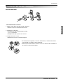
Required Parts Required Tools

Installation Manual 3
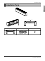
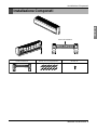
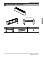
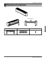
Installation Parts
ENGLISH
Installation plate
Type "A" screw and plastic anchor
Type "B" screw
Installation plate
Installation Parts

4 Indoor Unit
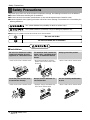
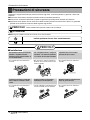
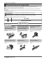
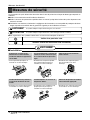
Safety Precautions
Safety Precautions
To prevent injury to the user or other people and property damage, the following instructions must be followed.
■ Be sure to read before installing the air conditioner.
■ Be sure to observe the cautions specified here as they include important items related to safety.
■ Incorrect operation due to ignoring instruction will cause harm or damage. The seriousness is classified by the
following indications.
■ Meanings of symbols used in this manual are as shown below.
This symbol indicates the possibility of death or serious injury.
This symbol indicates the possibility of injury or damage to properties only.
Be sure not to do.
Be sure to follow the instruction.
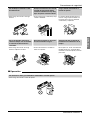
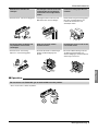
■ Installation
Do not use a defective or under-
rated circuit breaker. Use this
appliance on a dedicated circuit.
•Thereisriskoffireorelectricshock.
For electrical work, contact the
dealer, seller, a qualified electri-
cian, or an Authorized Service
Center.
• Do not disassemble or repair the
product. There is risk of fire or elec-
tric shock.
Always ground the product.
•Thereisriskoffireorelectricshock.
Install the panel and the cover
of control box securely.
•Thereisriskoffireorelectricshock.
Always install a dedicated cir-
cuit and breaker.
• Improper wiring or installation may
cause fire or electric shock
Use the correctly rated breaker
or fuse.
•Thereisriskoffireorelectricshock.

Installation Manual 5
Safety Precautions
ENGLISH
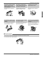
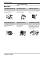
■ Operation
Do not modify or extend the
power cable.
• There is risk of fire or electric shock.
Do not let the air conditioner
run for a long time when the
humidity is very high and a door
or a window is left open.
• Moisture may condense and wet or
damage furniture.
Be cautious when unpacking
and installing the product.
• Sharp edges could cause injury. Be
especially careful of the case edges
and the fins on the condenser and
evaporator.
For installation, always contact
the dealer or an Authorized
Service Center.
• There is risk of fire, electric shock,
explosion, or injury.
Do not install the product on a
defective installation stand.
• It may cause injury, accident, or
damage to the product.
Be sure the installation area
does not deteriorate with age.
• If the base collapses, the air condi-
tioner could fall with it, causing prop-
erty damage, product failure, and
personal injury.
Do not store or use flammable gas or combustibles near the product.
• There is risk of fire or failure of product.
Gasolin

6 Indoor Unit
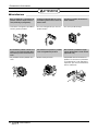
Safety Precautions
Always check for gas (refriger-
ant) leakage after installation or
repair of product.
• Low refrigerant levels may cause
failure of product.
Install the drain hose to ensure
that water is drained away prop-
erly.
• A bad connection may cause water
leakage.
Keep level even when installing
the product.
• To avoid vibration or water leakage.
Do not install the product where
the noise or hot air from the out-
door unit could damage the
neighborhoods.
• It may cause a problem for your
neighbors.
Use two or more people to lift
and transport the product.
• Avoid personal injury.
Do not install the product where
it will be exposed to sea wind
(salt spray) directly.
• It may cause corrosion on the product.
Corrosion, particularly on the con-
denser and evaporator fins, could
cause product malfunction or inefficient
operation.
90˚
■ Installation

Installation Manual 7
Installation
ENGLISH
Read completely, then follow step by step.
Installation
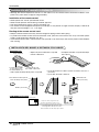
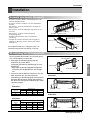
Selection of the best location
• There should not be any heat source or steam
near the unit.
• There should not be any obstacles to prevent the
air circulation.
• A place where air circulation in the room will be
good.
• A place where drainage can be easily obtained.
• A place where noise prevention is taken into con-
sideration.
• Do not install the unit near the door way.
• Ensure the spaces indicated by arrows from the
wall, ceiling, fence, or other obstacles.
The mounting wall should be strong and solid
enough to protect it from the vibration.
Front
Right Rear right
Rear left
Down right
Left
Lower than 2.3m
More than 20 cm
Higher than eye-level
More than
10 cm
More than
10 cm
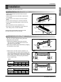
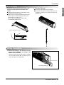
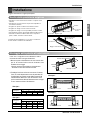
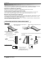
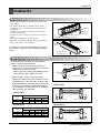
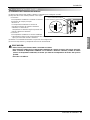
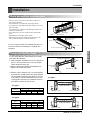
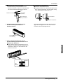
Fixing Installation Plate
The wall you select should be strong and solid
enough to prevent vibration
1. Mount the installation plate on the wall with
type "A" screws. If mounting the unit on a con-
crete wall, use anchor bolts.
• Mount the installation plate horizontally by aligning
the centerline using a level.
2. Measure the wall and mark the centerline. It is
also important to use caution concerning the loca-
tion of the installation plate-routing of the wiring to
power outlets is through the walls typically. Drilling
the hole through the wall for piping connections
must be done safely.
Installation Plate
Type "A" screw
Chassis
Hook
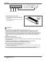
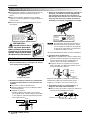
Installation plate
Left rear piping Right rear piping
Ø70mm
Ø70mm
DB
A
C
ABCD
S4 73 55 82 55
S5 121 62 258 62
CHASSIS
(Grade)
Distance (mm)
ABCD
S4 50 105 59 105
SE 65 110 85 110
S5 95 122 235 122
CHASSIS
(Grade)
Distance (mm)
Installation plate
Left rear piping Right rear piping
Ø70mm
Ø70mm
D
B
A
C
Type 1.
Type 1.
Type 2.
Type 2.

8 Indoor Unit
Installation
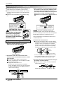
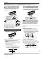
Piping Method
CAUTION : When
install, make sure that
the remaining parts must be
removed clearly so as not to
damage the piping and drain
hose, especially power cord
and connecting cable.
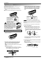
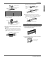
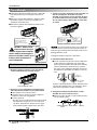
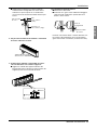
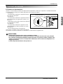
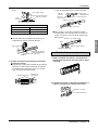
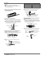
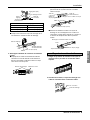
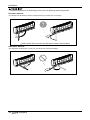
■ Preparing the indoor unit's piping and drain hose for
installation through the wall.
■ Remove the plastic tubing retainer(see illustration
below) and pull the tubing and drain hose away from
chassis.
■ Replace the plastic tubing holder in the original position.
1. Route the indoor tubing and the drain hose in the
direction of rear left.
2. Insert the connecting cable into the indoor unit
from the outdoor unit through the piping hole.
■ Do not connect the cable to the indoor unit.
■ Make a small loop with the cable for easy connection
later.
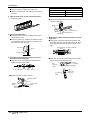
■ Drill a hole in the wall
• Drill the piping hole with a ø70mm hole core drill.
Drill the piping hole at either the right or the left with
the hole slightly slanted to the outdoor side.
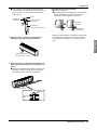
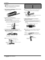
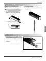
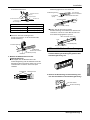
3. Tape the tubing, drain hose and the connecting
cable. Be sure that the drain hose is located at the
lowest side of the bundle. Locating at the upper
side can cause drain pan to overflow inside the
unit.
: If the drain hose is routed inside the room,
insulate the hose with an insulation material* so that drip-
ping from "sweating"(condensation) will not damage furni-
ture or floors.
*Foamed polyethylene or equivalent is recommended.
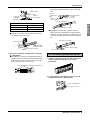
4. Indoor unit installation
■ Hook the indoor unit onto the upper portion of the
installation plate.(Engage the two hooks of the rear
top of the indoor unit with the upper edge of the
installation plate.) Ensure that the hooks are properly
seated on the installation plate by moving it left and
right.
Press the lower left and right sides of the unit against
the installation plate until the hooks engage into their
slots(clicking sound).
5. Connecting the pipings to the indoor unit and drain
hose to drain pipe.
■ Align the center of the pipings and sufficiently tighten
the flare nut by hand.
NOTICE
For left rear piping
To remove the holder,
press the bottom of
chassis near the holder
upward and pull the tab
out of its hole.
Tubing holder
Pull
Press
2
1
Drain hose
Connecting
cable
Loop
Gas side
piping
Liquid side
piping
Drain hose
Drain hose
Connecting
cable
Indoor unit tubing
Flare nut Pipings
5-7mm
(3/16"~5/16")
Indoor
WALL
Outdoor

Installation Manual 9
Installation
ENGLISH
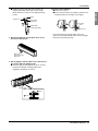
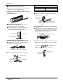
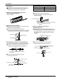
■ Tighten the flare nut with a wrench.
■ When extending the drain hose at the indoor unit,
install the drain pipe.
6. Wrap the insulation material around the connect-
ing portion.
■ Overlap the connection pipe insulation material
and the indoor unit pipe insulation material. Bind
them together with vinyl tape so that there is no
gap.
■ Wrap the area which accommodates the rear pip-
ing housing section with vinyl tape.
■ Bundle the piping and drain hose together by
wrapping them with vinyl tape over the range with-
in which they fit into the rear piping housing sec-
tion.
1. Route the indoor tubing and the drain hose to the
required piping hole position.
2. Insert the piping, drain hose and the connecting
cable into the piping hole.
GAS LIQUID
Ø12.7[5.5kg
.
m] Ø6.35[1.8kg
.
m]
Ø15.88[6.6kg
.
m] Ø9.52[4.2kg
.
m]
Pipe Size[Torque]
For right rear piping
Torque
wrench
Indoor
unit tubing
Spanner (fixed)
Connection
pipe
Flare nut
Vinyl tape(narrow)
Connection
pipe
Connecting cable
Vinyl tape
(wide)
Wrap with vinyl tape
Indoor
unit pipe
Pipe
Wrap with vinyl tape
Drain hose
Pipe
Vinyl tape(wide)
Drain pipe
Connecting cable
Vinyl tape(narrow)
Adhesive
Drain pipe
Indoor unit
drain hose
Plastic bands
Insulation material

10 Indoor Unit
Installation
3. Insert the connecting cable into the indoor unit.
■ Don't connect the cable to the indoor unit.
■ Make a small loop with the cable for easy connec-
tion later.
4. Tape the drain hose and the connecting cable.
• Connecting cable
5. Indoor unit installation
■ Hang the indoor unit from the hooks at the top of
the installation plate.
■ Insert the spacer etc. between the indoor unit and
the installation plate and separate the bottom of
the indoor unit from the wall.
6. Connecting the pipings to the indoor unit and
the drain hose to drain pipe.
■ Align the center of the pipings and sufficiently
tighten the flare nut by hand.
■ Tighten the flare nut with a wrench.
■ When extending the drain hose at the indoor unit,
install the drain pipe.
7. Wrap the insulation material around the connect-
ing portion.
■ Overlap the connection pipe heat insulation and
the indoor unit pipe heat insulation material. Bind
them together with vinyl tape so that there is no
gap.
■ Wrap the area which accommodates the rear pip-
ing housing section with vinyl tape.
Vinyl tape
Adhesive
Drain hose
Indoor unit drain hose
(narrow)
Plastic bands
Insulation material
Vinyl tape
(narrow)
Connection
pipe
Connecting
cable
Indoor
unit piping
Pipe
Vinyl tape
(wide)
Wrap with vinyl tape
Installation plate
Spacer
Indoor unit
8cm
Indoor unit tubing
Flare nut Pipings
Torque
wrench
Indoor
unit tubing
Spanner (fixed)
Connection
pipe
Flare nut
GAS LIQUID
Ø12.7[5.5kg
.
m] Ø6.35[1.8kg
.
m]
Ø15.88[6.6kg
.
m] Ø9.52[4.2kg
.
m]
Pipe Size[Torque]

Installation Manual 11
Installation
ENGLISH
■ Bundle the piping and drain hose together by
wrapping them with cloth tape over the range
within which they fit into the rear piping housing
section.
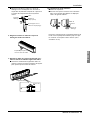
8. Reroute the pipings and the drain hose across
the back of the chassis.
9. Set the pipings and the drain hose to the back of
the chassis with the tubing holder.
■ Hook the edge of tubing holder to tap on chassis
and push the bottom of tubing holder to be
engaged at the bottom of chassis.
10. Indoor unit installation
■ Remove the spacer.
■ Ensure that the hooks are properly seated on the
installation plate by moving it left and right.
Press the lower left and right sides of the unit
against the installation plate until the hooks engage
into their slots(clicking sound).
Drain hose
Vinyl tape
(narrow)
Pipe
Wrap with
vinyl tape(wide)
Drain hose
Connecting
cable
Piping for
passage through
piping hole
Tubing holder
Hook
Push
2
1

12 Indoor Unit
Installation
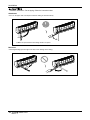
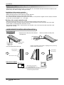
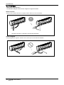
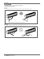
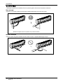
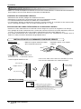
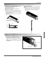
Installation Information. For left piping. Follow the instruction below.
Good case
• Press on the upper side of clamp and unfold the tubing to downward slowly.
Bad case
• Following bending type from right to left may cause damage to the tubing.
Make the space between the tubing and the rear panel

Installation Manual 13
ENGLISH
Installation
Drain Piping
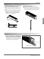
Wiring Connection
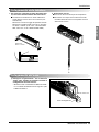
1. To remove the front panel from the indoor unit,
remove the front panel from the indoor unit
cabinet.
■ Set the air direction louvers up-and-down to the
position(horizontally) by hand.
■ Remove the securing screws that retain the front
panel. Pull the lower left and right sides of the
grille toward you and lift it off.
(2.1/7, 2.6/9, 3.5/12 kW/Btu models: 2EA,
3.5/18 kW/Btu models: 3EA)
2. To check the drainage.
■ Pour a glass of water on the evaporator.
■ Ensure the water flows through the drain hose of
the indoor unit without any leakage and goes out
the drain exit.
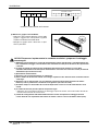
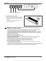
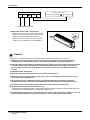
1) Connect the wires to the terminals on the
control board individually according to the
outdoor unit connection.
• Ensure that the color of the wires of outdoor
unit and the terminal No. are the same as
those of indoor unit respectively.
Screw
Pull the right and the left side.
Connecting cable
Remote control cordRemote control cordRemote control cord

14 Indoor Unit
Installation
CAUTION:
After the confirmation of the above conditions, prepare the wiring as follows:
1) Never fail to have an individual power circuit specifically for the air conditioner. As for the
method of wiring, be guided by the circuit diagram posted on the inside of control cover.
2) The screw which fasten the wiring in the casing of electrical fittings are liable to come loose from
vibrations to which the unit is subjected during the course of transportation. Check them and
make sure that they are all tightly fastened. (If they are loose, it could cause burn-out of the
wires.)
3) Specification of power source.
4) Confirm that electrical capacity is sufficient.
5) See to that the starting voltage is maintained at more than 90 percent of the rated voltage marked
on the name plate.
6) Confirm that the cable thickness is as specified in the power source specification.
(Particularly note the relation between cable length and thickness.)
7) In a wet or moist area, always install an earth leakage circuit breaker.
8) The following would be caused by voltage drop.
• Vibration of a magnetic switch, which will damage the contact point, fuse breaking, disturbance of the
normal function of the overload.
9) The means for disconnection from a power supply shall be incorporated in the fixed wiring and
have an air gap contact separation of at least 3mm in each active(phase) conductors.
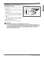
2) Attach the Grille onto the cabinet.
• Grasp lower the left and right side of the Grille
and engage four tabs on the top inside edge
of the chassis.
• Press the Grille toward the chassis until it will
be back into place.
Terminal Block in Indoor
1(L) 2(N) 3 4
INDOOR POWER INPUT
Terminal Block in Outdoor
ABC D Vcc

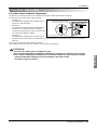
Installation Manual 15
ENGLISH
Installation
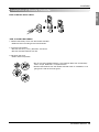
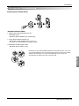
1. Remove the battery cover from the remote controller.
• Slide the cover according to the arrow direction.
2. Insert the two batteries.
• Be sure that the (+) and (-) directions are correct.
• Be sure that both batteries are new.
3. Re-attach the cover.
• Slide it back into position.
HOW TO MOUNT ONTO A WALL
HOW TO INSERT BATTERIES
Installation of Remote Controller
• Do not use rechargeable batteries, such batteries differ from standard dry
cells in shape, dimensions, and performance.
• Romove the batteries from the remote controller if the air conditioner is not
going to be used for some long time.

16 Indoor Unit
Installation
Remote controller
box body
Cord clamp
(accessory)
Lever carefully
the box open
using a screw
driver, etc.
Front case
The lower part
Face of wall
Under plate
Screw (accessory)
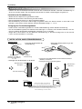
• Separate the under plate from Remote
controller box.
• Attach insulator to under plate.
• Fix the under plate on the wall
•
Fix the cord clamps on the wall by ø 3 tapping screws (accessory).
•
Fix the remote controller cord.
WIRED REMOTE CONTROLLER INSTALLATION
DISASSEMBLING
ELECTRICAL WIRING
Wire and make sure that teminal
numbers are matched on unit side and
remote controller side.
The maximum length of the cord is 100m.
If the length of the cord exceeds 50m,
use a wire size greater than 0.5mm
2
.
Remote controller
(Main board)
CN REMO
• Although the room temperature sensor is in the indoor unit, the remote controller should be installed in such
places away from direct sunlight and high humidity.
Installation of the remote controller
• Select places that are not splashed with water.
• Select controller position after receiving customer approval.
• The room temperature sensor is built in the indoor unit.
• This remote controller equipped with liquid crystal display. If this position is higher or lower, display is difficult
to see.(The standard height is 1.2 ~1.5m high)
Routing of the remote controller cord
• Keep the remote controller cord away from the refrigerant piping and the drain piping.
• To protect the remote controller cord from electrical noise, place the cord at least 5cm away from other
power cables. (audio equipment. television set, etc.)
• If the remote controller cord is secured to the wall, provide a trap at the top of the cord to prevent water
droplets from running.
Installation of Remote Control

Installation Manual 17
ENGLISH
Installation
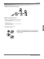
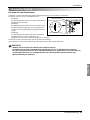
1) Two Thermistor System
(1) Open the rear cover of the wired remote-controller to
set the mode.
(2) Select one of three selectable modes as follows.
• Position 1:
The room temperature is controlled by the thermistor
of the main body.
• Position 2:
The room themperature is controlled by the thermis-
tor of the wired remote-controller, control the temper-
ature according to the position of wired remote-con-
troller.
• Position 3:
The room temperature is controlled by lower temper-
ature between the temperature of main body and of
remote-controller sensor.
(3) Move the slide switch to set position.
(4) Close the rear cover and check if it works normally.
TH
R14H
SW TH
REMO
MAIN
2TH
OP7
R18H
R17H
OP6
LO
STAND
SW HIGH
HI
R03S
C070
R04S
R02S
R01S
OP3
OP2 OP1
R19H
R11H
R13H R12H
OP5R16H OP4
R15H
CO1H
REMO
Room Temp. sensor
2TH
MAIN
Position 2
Position 1
Position 3
Slide switch for ceiling height
Slide switch for 2 Thermistor
Optional operation
CAUTION :
• Select the position after counselling with a customer.
In case of cooling mode, room temperature is controlled by the main body sensor.
• To control the room temperature by a wired remote controller, install the remote
controller (room temp. sensor) to sense the temperature more accurately.
• Maunfactured in the position 3.

18 Indoor Unit
Memo

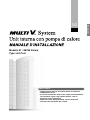
LG
Modello N °: SE/S5 Series
Type: Art Cool
IMPORTANTE
• Leggere questo manuale d’istruzioni prima di installare il
condizionatore d’aria.
• Il lavoro d’installazione deve essere eseguito conformemente
alla normativa vigente sugli impianti elettrici, solo da
personale tecnico autorizzato.
• Dopo averlo letto dettagliatamente, conservare questo
manuale come riferimento per il futuro
ITALIANO

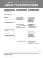
2 Unità interna
Installazione dell’unità interna a parete
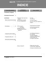
INDICE
❏ Modello di carta per instal-
lazione
❏ Vitie tasselli in plastica
❏ Cavo di collegamento
❏ Tubi: lato gas
lato liquido
❏ Materiale isolante
❏ Tubo flessible discarico
aggiuntivo
❏
Due viti di tipo "B"
❏ Livella
❏
Cacciavite
❏
Trapano elettrico
❏
Punta a tazza per allargare i fori
❏ Metro
❏ Set utensili per svasatura
❏ Chiavi dinamometriche
❏ Chiave inglese
❏ Un bicchiere d'acque=a
❏ Ca cciavite
❏ Chiave esagonale
❏ Rilevatore perdite di gas
❏ Pompa del vuoto
❏ Gruppo manometrico
❏ Manuale di istruzioni
❏ Termometro ambientale
❏ Supporto del telecomando
Installazione Componeti........3
Precauzioni di sicurezza ......4
Installazione
Scelta della posizione migliore
................................................7
Pipa Metodo...........................8
Collegamento delle tubature
..............................................13
Collegamento del cavo........13
Installazione del telecomando
..............................................15
Lavori di installazione
Componenti
dell’installazione
Arnesi richiesti
La page est en cours de chargement...
La page est en cours de chargement...
La page est en cours de chargement...
La page est en cours de chargement...
La page est en cours de chargement...
La page est en cours de chargement...
La page est en cours de chargement...
La page est en cours de chargement...
La page est en cours de chargement...
La page est en cours de chargement...
La page est en cours de chargement...
La page est en cours de chargement...
La page est en cours de chargement...
La page est en cours de chargement...
La page est en cours de chargement...
La page est en cours de chargement...
La page est en cours de chargement...
La page est en cours de chargement...
La page est en cours de chargement...
La page est en cours de chargement...
La page est en cours de chargement...
La page est en cours de chargement...
La page est en cours de chargement...
La page est en cours de chargement...
La page est en cours de chargement...
La page est en cours de chargement...
La page est en cours de chargement...
La page est en cours de chargement...
La page est en cours de chargement...
La page est en cours de chargement...
La page est en cours de chargement...
La page est en cours de chargement...
La page est en cours de chargement...
La page est en cours de chargement...
La page est en cours de chargement...
La page est en cours de chargement...
La page est en cours de chargement...
La page est en cours de chargement...
La page est en cours de chargement...
La page est en cours de chargement...
La page est en cours de chargement...
La page est en cours de chargement...
La page est en cours de chargement...
La page est en cours de chargement...
La page est en cours de chargement...
La page est en cours de chargement...
La page est en cours de chargement...
La page est en cours de chargement...
La page est en cours de chargement...
La page est en cours de chargement...
La page est en cours de chargement...
La page est en cours de chargement...
La page est en cours de chargement...
La page est en cours de chargement...
La page est en cours de chargement...
La page est en cours de chargement...
La page est en cours de chargement...
La page est en cours de chargement...
La page est en cours de chargement...
La page est en cours de chargement...
La page est en cours de chargement...
La page est en cours de chargement...
La page est en cours de chargement...
La page est en cours de chargement...
La page est en cours de chargement...
La page est en cours de chargement...
La page est en cours de chargement...
La page est en cours de chargement...
La page est en cours de chargement...
La page est en cours de chargement...
-
 1
1
-
 2
2
-
 3
3
-
 4
4
-
 5
5
-
 6
6
-
 7
7
-
 8
8
-
 9
9
-
 10
10
-
 11
11
-
 12
12
-
 13
13
-
 14
14
-
 15
15
-
 16
16
-
 17
17
-
 18
18
-
 19
19
-
 20
20
-
 21
21
-
 22
22
-
 23
23
-
 24
24
-
 25
25
-
 26
26
-
 27
27
-
 28
28
-
 29
29
-
 30
30
-
 31
31
-
 32
32
-
 33
33
-
 34
34
-
 35
35
-
 36
36
-
 37
37
-
 38
38
-
 39
39
-
 40
40
-
 41
41
-
 42
42
-
 43
43
-
 44
44
-
 45
45
-
 46
46
-
 47
47
-
 48
48
-
 49
49
-
 50
50
-
 51
51
-
 52
52
-
 53
53
-
 54
54
-
 55
55
-
 56
56
-
 57
57
-
 58
58
-
 59
59
-
 60
60
-
 61
61
-
 62
62
-
 63
63
-
 64
64
-
 65
65
-
 66
66
-
 67
67
-
 68
68
-
 69
69
-
 70
70
-
 71
71
-
 72
72
-
 73
73
-
 74
74
-
 75
75
-
 76
76
-
 77
77
-
 78
78
-
 79
79
-
 80
80
-
 81
81
-
 82
82
-
 83
83
-
 84
84
-
 85
85
-
 86
86
-
 87
87
-
 88
88
-
 89
89
-
 90
90


LG ARNU18GS5A1.AMBAIDA Guide d'installation
- Taper
- Guide d'installation
- Ce manuel convient également à
dans d''autres langues
Documents connexes
-
LG ARNU243S8R2.ANCALUS Guide d'installation
-
LG ARNU123SEL2.AMBALUS Guide d'installation
-
LG ARNU073SER2 Guide d'installation
-
LG ARNU24GS5L2.EMBAAAS Guide d'installation
-
LG ARNU18GS5L2.EMBAAAS Guide d'installation
-
-
LG ARNU12GSER2.ENCAAAS Guide d'installation
-
LG PM05SP.NSJ Manuel utilisateur
-
LG MS07ET Le manuel du propriétaire
-