Toro 18" Brush Cutter Manuel utilisateur
- Catégorie
- Outils de jardin
- Taper
- Manuel utilisateur

Operator’s Manual
Manuel de l’Utilisateur
Manual del Usuario
FORM NO. 3318–352 REV A
Gas Trimmer/Brushcutter
Model No. 51918 — 690000001 & Up
Model No. 51919 — 690000001 & Up
Coupe–herbe/débroussailleuse à essence
Modèle No. 51918 — 690000001 et suivants
Modèle No. 51919 — 690000001 et suivants
Recortadora de setos/Cortadora de maleza a
gasolina
Modelo No. 51918 — 690000001 y siguientes
Modelo No. 51919 — 690000001 y siguientes

The engine exhaust from this product
contains chemicals known to the State of
California to cause cancer, birth defects,
or other reproductive harm.
WARNING:
Les gaz d’échappement du moteur de ce
produit contiennent des produits
chimiques reconnus dans l’état de
Californie comme cancérigènes,
responsables de malformations
congénitales, ou comme nocifs à l’égard
des fonctions de la reproduction.
AVERTISSEMENT:
El escape del motor de esta herramienta
contiene productos químicos que según
la información del Estado de California
producen cáncer, defectos congénitos u
otros riesgos reproductivos.
ADVERTENCIA:

The Toro Company – 1995, Rev. 1998
All Rights Reserved
Printed in USA
i
Figures–Figuras
1
English
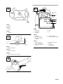
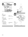
1. Model and serial number decal location
Français
1. Emplacement des numéros de série et de modèle
Español
1. Ubicación de la calcomanía con el modelo y el número de serie
1
2
3
4

ii
2
3
5
1
4
English
1. String guard
2. Blade guard
3. Locking rod
4. Washer
5. Bump head
Français
1. Pare–fil
2. Carter de lame
3. Goupille de blocage
4. Rondelle
5. Tête de percussion
Español
1. Protector de la cuerda
2. Protector de la cuchilla
3. Pasador de fijación
4. Arandela
5. Cabeza de tope
1
2
3
4
5
English
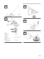
1. Blade guard
2. Locking rod
3. Blade
4. Washer
5. Lock nut
Français
1. Carter de lame
2. Goupille de blocage
3. Lame
4. Rondelle
5. Contre–écrou
Español
1. Protector de la cuchilla
2. Pasador de fijación
3. Cuchilla
4. Arandela
5. Contratuerca
5 6
7

iii
English
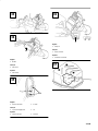
1. 1/2 turn
Français
1. 1/2 tour
Español
1. 1/2 vuelta
1
English
1. Blade locating mark
Français
1. Marque de repérage
Español
1. Marca de referencia de la cuchilla
1
3
4
5
2
English
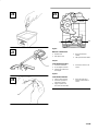
1. Primer bulb
2. Choke lever
3. Full choke
4. Partial
5. Run
Français
1. Amorceur
2. Manette de starter
3. Fermeture complète
(CHOKE)
4. Ouverture partielle
5. Position de marche (RUN)
Español
1. Perilla de cebado
2. Palanca del obturador
3. Posición de obturación
total
4. Posición de obturación
parcial
5. Posición de
funcionamiento
8
9
10
11

iv
1
2
English
1. Starter rope 2. Throttle trigger
Français
1. Corde du lanceur 2. Gâchette de la commande
des gaz
Español
1. Cuerda de arranque 2. Gatillo del acelerador
1
English
1. Stand
Français
1. Support
Español
1. Soporte
12
13
14
15

v
2
3
1
English
1. String guard
2. Inner reel
3. Bump knob
Français
1. Pare–fil
2. Bobine intérieure
3. Bouton de percussion
Español
1. Protector de la cuerda
2. Carrete interior
3. Botón de tope
16
17
18
19
20

vi
1
English
1. Fill plug
Français
1. Bouchon
Español
1. Tapón de llenado
1
2
2
English
1. Choke lever 2. Screws
Français
1. Manette de starter 2. Vix
Español
1. Palanca del obturador 2. Tornillos
1
English
1. Air filter
Français
1. Filtre à air
Español
1. Filtro de aire
21
22
23
24
25

vii
1
2
3
4
English
WALBRO CARBURETOR
1. Throttle lever
2. Idle speed screw
3. High speed mixture
needle
4. Idle speed mixture needle
Français
CARBURATEUR WALBRO
1. Levier d’accélérateur
2. Vis de régime de ralenti
3. Pointeau de richesse de
haut régime
4. Pointeau de richesse de
ralenti
Español
CARBURADOR WALBRO
1. Palanca del acelerador
2. Tornillo de ajuste de la
velocidad en ralentí
3. Aguja de ajuste de la
mezcla de alta velocidad
4. Aguja de ajuste de la
mezcla de velocidad en
ralentí
26
27
28
29

viii
1
2
3
4
English
ZAMA CARBURETOR
1. Throttle lever
2. Idle speed screw
3. High speed mixture
needle
4. Idle speed mixture needle
Français
CARBURATEUR ZAMA
1. Levier d’accélérateur
2. Vis de régime de ralenti
3. Pointeau de richesse de
haut régime
4. Pointeau de richesse de
ralenti
Español
CARBURADOR ZAMA
1. Palanca del acelerador
2. Tornillo de ajuste de la
velocidad en ralentí
3. Aguja de ajuste de la
mezcla de alta velocidad
4. Aguja de ajuste de la
mezcla de velocidad en
ralentí
0.020 in
(0,5 mm)
2
1
English
1. Rear engine cover 2. Screw
Français
1. Capot arrière 2. Vis
Español
1. Tapa trasera del motor 2. Tornillo
30 31
32

ix
1
English
1. Muffler
Français
1. Silencieux
Español
1. Silenciador
2
1
English
1. Exhaust exit tube 2. Screws
Français
1. Tuyau d’échappement 2. Vis
Español
1. Tubo de escape 2. Tornillos
1
English
1. Inlet port
Français
1. Orifice d’entrée
Español
1. Lumbrera de entrada
33
34
35
36
37

EN–1
Contents
Page
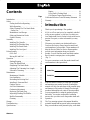
Introduction 1. . . . . . . . . . . . . . . . . . . . . . . . . . . .
Safety 2. . . . . . . . . . . . . . . . . . . . . . . . . . . . . . . . .
Fueling And Before Operating 2. . . . . . . . . .
While Operating 3. . . . . . . . . . . . . . . . . . . . .
Safety Warnings For The Brush Blade
During Use 3. . . . . . . . . . . . . . . . . . . . . . .
Maintenance And Storage 4. . . . . . . . . . . . .
Safety and Instruction Decals 5. . . . . . . . . .
Symbol Glossary 6. . . . . . . . . . . . . . . . . . . .
Assembly 7. . . . . . . . . . . . . . . . . . . . . . . . . . . . . .
Installing The J-handle 7. . . . . . . . . . . . . . . .
Installing The Shoulder Strap 7. . . . . . . . . .
Installing The Brush Blade 7. . . . . . . . . . . .
Installing The Line Spool 7. . . . . . . . . . . . . .
Before Starting 8. . . . . . . . . . . . . . . . . . . . . . . . . .
Oil & Fuel 8. . . . . . . . . . . . . . . . . . . . . . . . .
Mixing Oil And Fuel 9. . . . . . . . . . . . . . . . .
Operation 9. . . . . . . . . . . . . . . . . . . . . . . . . . . . . .
Starting/Stopping 9. . . . . . . . . . . . . . . . . . . .
Using The Brush Blade 10. . . . . . . . . . . . . . .
Sharpening The Brush Blade 10. . . . . . . . . . .
Adjusting The Trimming Line Length 10. . . .
Decorative Trimming 10. . . . . . . . . . . . . . . . .
Maintenance 11. . . . . . . . . . . . . . . . . . . . . . . . . . . .
Maintenance Schedule 11. . . . . . . . . . . . . . . .
Line Installation 11. . . . . . . . . . . . . . . . . . . . .
Rewinding the Existing Reel 11. . . . . . . . . . .
Installing A Prewound Reel 12. . . . . . . . . . . .
Gearbox Service 12. . . . . . . . . . . . . . . . . . . . .
Air Filter Maintenance 12. . . . . . . . . . . . . . . .
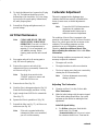
Carburetor Adjustment 13. . . . . . . . . . . . . . . .
Replacing The Spark Plug 14. . . . . . . . . . . . .
Inspecting/Cleaning The Muffler 14. . . . . . . .
Muffler Reassembly 15. . . . . . . . . . . . . . . . . .
Cleaning 16. . . . . . . . . . . . . . . . . . . . . . . . . . .
Storage 16. . . . . . . . . . . . . . . . . . . . . . . . . . . . . . . .
Troubleshooting 17. . . . . . . . . . . . . . . . . . . . . . . . .
Specifications 18. . . . . . . . . . . . . . . . . . . . . . . . . . .
Engine 18. . . . . . . . . . . . . . . . . . . . . . . . . . . .
Drive Shaft & Cutting Head 18. . . . . . . . . . .
Cold Engine Torque Specifications 18. . . . . .
California Emission Control Warranty Statement 19
Warranty 21. . . . . . . . . . . . . . . . . . . . . . . . . . . . . . .
Introduction
Thank you for purchasing a Toro product.
All of us at Toro want you to be completely satisfied
with your new product, so feel free to contact your
local Authorized Service Dealer for help with service,
genuine Toro parts, or other information you may
require.
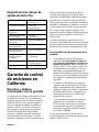
Whenever you contact your Authorized Service
Dealer or the factory, always know the model and
serial numbers of your product. These numbers will
help the Service Dealer or Service Representative
provide exact information about your specific
product. You will find the model and serial number
decal located in a unique place on the product
(Fig. 1).
For your convenience, write the product model and
serial numbers in the space below.
Model No.
Serial No.
Read this manual carefully to learn how to operate
and maintain your product correctly. Reading this
manual will help you and others avoid personal injury
and damage to the product. Although Toro designs,
produces and markets safe, state-of-the-art products,
you are responsible for using the product properly
and safely. You are also responsible for training
persons who you allow to use the product about safe
operation.
The Toro warning system in this manual identifies
potential hazards and has special safety messages that
help you and others avoid personal injury, even death.

EN–2
DANGER, WARNING and CAUTION are signal
words used to identify the level of hazard. However,
regardless of the hazard, be extremely careful.
DANGER signals an extreme hazard that will cause
serious injury or death if the recommended
precautions are not followed.
WARNING signals a hazard that may cause serious
injury or death if the recommended precautions are
not followed.
CAUTION signals a hazard that may cause minor or
moderate injury if the recommended precautions are
not followed.
Two other words are also used to highlight
information. “Important” calls attention to special
mechanical information and “Note” emphasizes
general information worthy of special attention.
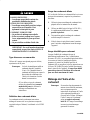
Safety
Note: For users on U. S. Forest Land and
in the states of California, Maine,
Oregon and Washington. All U.S.
Forest Land and the state of California
(Public Resources Codes 4442 and
4443), Oregon and Washington
require, by law that certain internal
combustion engines operated on forest
brush and/or grass-covered areas be
equipped with a spark arrestor,
maintained in effective working order,
or the engine be constructed, equipped
and maintained for the prevention of
fire. Check with your state or local
authorities for regulations pertaining to
these requirements. Failure to follow
these requirements could subject you
to liability or a fine. This unit is not
factory equipped with a spark
arrestor. If these items are required in
your area, ask your dealer to install the
Optional Accessory Part #180030
Spark Arrestor Kit.
Fueling And Before Operating
1. Gasoline is extremely flammable and its vapors
can explode if ignited. Always stop the engine
and allow it to cool before filling the fuel tank.
Do not smoke while filling the fuel tank. Keep
sparks and open flames away from the area.
2. Store gasoline and fuel only in containers
designed and approved for the storage of such
materials.
3. Pressure can build up in the fuel tank. Loosen
the fuel tank cap slowly to relieve any pressure
in the tank.
4. Add fuel in a clean, well-ventilated area. Wipe
up any spilled fuel immediately. If fuel has been
spilled, allow it to dry completely before starting
the engine.
5. Move the trimmer at least 10 ft (3 m) from the
fueling point before starting the engine.
6. Thoroughly inspect the trimmer for loose or
damaged parts before each use. Do not use until
adjustments or repairs are made.
7. Avoid accidental starting. Be in the starting
position whenever pulling the starting rope.
8. Keep all bystanders, especially children, and pets
at least 33 ft (10 m) away from the area.
9. Carefully inspect the areas to be cut. Remove all
debris that could become entangled in the string
or blade. Also remove any objects that could be
thrown during cutting.
10. Before starting, make sure the string head is not
in contact with anything.
11. Always remain alert. To prevent injury to
yourself and others, do not operate this trimmer
if you are fatigued.
12. Do not operate the unit while under the influence
of drugs, alcohol or medication.
While Operating
1. Wear safety glasses or goggles at all times when
operating this trimmer.

EN–3
2. Dress properly. Do not operate this trimmer
when barefoot or wearing open sandals. Always
wear sturdy, rubber-soled footwear. The use of
gloves, ear/hearing protection and long pants are
recommended.
3. Do not wear loose fitting clothing or articles
such as scarves, strings, chains, ties, etc. because
they could get drawn into the air intake. Also
make sure long hair does not get drawn into the
air intake.
4. Keep hands, face, and feet away from all moving
parts. Do not attempt to touch or stop the string
when it is rotating.
5. Do not touch the muffler or cylinder. These parts
get extremely hot from operation and remain hot
for a short time after the equipment is turned off.
6. Always hold the trimmer with both hands when
operating. Keep a firm grip on both the front and
rear handles or grips.
7. Operate this trimmer only in a well-ventilated
area — outdoors. Carbon monoxide exhaust
fumes can be lethal in a confined area.
8. If the unit strikes or becomes entangled with a
foreign object, stop the engine immediately and
check for damage. Repair any damage before
further operation is attempted. Do not operate
the trimmer with loose or damaged parts.
9. Use the right tool. Do not use this trimmer for
any job except that for which it is intended.
10. Do not force the tool at a rate faster than the rate
at which it is able to cut effectively.
11. Do not overreach. Keep proper footing and
balance at all times.
12. Do not operate the engine faster than the speed
necessary to cut, trim or edge. Do not run the
engine at high speed when not cutting.
13. The string guard must be in place at all times
while operating as a trimmer.
14. Do not extend the trimming line beyond the
length specified in this manual.
15. Always stop the engine when cutting is delayed
or when walking from one cutting location to
another.
16. Use only genuine replacement parts when
servicing this trimmer. These parts are available
from your authorized dealer. The use of
non-standard parts, or other accessories or
attachments not designed for this trimmer, could
result in serious injury to the user or damage to
the trimmer and void your warranty.
Safety Warnings For The
Brush Blade During Use
1. Read the safety instructions starting on page 2.
2. Always use the shoulder harness when using the
brush blade accessory.
3. Keep the J-handle between the operator and
cutting head at all times.
4. Do not under any conditions cut with the blade
located over 30 inches (76.2 cm) or more above
the ground level.
5. Scything should be done with extreme care and
caution.
6. For operation with the standard 4-tooth blade, do
not cut anything thicker than 1/2 inch or a
violent kickback could occur.
7. Do not attempt to touch or stop the blade when it
is rotating.
8. Do not run the unit at high speed when not
cutting.
9. If you strike or become entangled with a foreign
object, stop the engine immediately and check
for damage. Have any damage repaired before
further operation is attempted. Do not operate
unit with a bent, cracked or dull blade.
10. Keep the unit clean of vegetation and other
materials. They may become lodged between the
blade and guard.

EN–4
11. Stop the engine IMMEDIATELY if you feel
excessive vibration. Vibration is a sign of
trouble. Inspect thoroughly for loose nuts, bolts
or damage before continuing. Repair or replace
affected parts as necessary.
Maintenance And Storage
1. Clean blade with a household cleaner to remove
any gum buildup. Then oil the blade with
machine oil to prevent rust.
2. Lock up and store the trimmer in an appropriate
and dry location to prevent unauthorized use and
damage. Keep unit out of the reach of children.
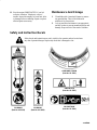
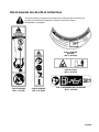
Safety and Instruction Decals
Safety decals and instructions are easily visible to the operator and are located near
any area of potential danger. Replace any decal that is damaged or lost.
ON SHROUD
(Part No. 92-3332)
ON BOOM
(Part No. 92-3328)
ON GAS TANK
(Part No. 92-3334)
ON BOOM
(Part No. 92-3323)
ON BLADE GUARD
(Part No. 92-3325)

EN–5
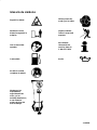
Symbol Glossary
Hot surface
Wear eye and hearing
protection
Stay a safe distance
from the machine
Thrown or flying
objects–Whole body
exposure
Read operator’s
manual
For service
information, call:
1–800–237–2654
Fuel Oil
Do not sharpen brush
blade
Keep bystanders,
especially children
and pets, at least 30 ft
(10 m) away from the
cutting area.

EN–6
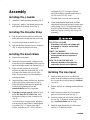
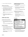
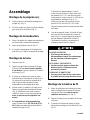
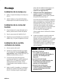
Assembly
Installing The J-handle
1. Install the J-handle mounting assembly (Fig. 2).
2. Adjust the J-handle to the desired position, and
then tighten the mounting screws (Fig. 2).
Installing The Shoulder Strap
1. Take the end of the shoulder strap without the
buckle and push it through the ring on the snap.
2. Loop the strap through the buckle (Fig. 3).
3. Snap the shoulder strap onto the wire connector
(Fig. 4). Adjust the length of the strap.
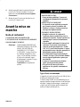
Installing The Brush Blade
1. Remove the string guard.
2. Insert the locking rod into the locking rod slot.
Rotate the line spool clockwise. Remove the line
spool and retainer washer from the shaft (Fig. 5).
3. Make sure that you have all of the parts
necessary to install the brush blade (Fig. 6). Do
not remove the blade tooth cover off of the
blade. Always wear gloves while handling or
installing the blade.
4. Install the blade, washer, and lock nut. Insert the
locking rod into the locking rod slot (Fig. 6).
Make sure that the blade stays flat against the
washer while tightening the lock nut
counterclockwise until it is finger-tight.
5. If you have a torque wrench, tighten the lock
nut to 225-250 in•lb (25.3-28.1 N•m), while
holding the locking rod in the locking rod slot
(Fig. 6).
If you do not have a torque wrench, thread the
lock nut onto the brush blade by hand as tightly
as possible (Fig. 7). Using an open-ended
wrench, rotate the nut 1/2 – 3/4 of a full turn
(minimum) (Fig. 8). The torque of the nut
should be within the required specifications of
225-250 in•lb (25.3-28.1 N•m).
The blade tooth cover can now be removed.
6. When assembling the brush blade, the blade
edge should line up with the blade locating mark
on the casting (Fig. 9). The brush blade should
be within a blade thickness of the mark. If the
blade isn’t lined up correctly, refer to Fig. 6 for
reassembly.
POTENTIAL HAZARD
• If the blade is off-center, the trimmer will
be damaged by vibration, and the blade
may fly off.
WHAT CAN HAPPEN
• Contact with thrown blade could cause
serious personal injury to operator or
bystanders.
HOW TO AVOID THE HAZARD
• Make sure the blade is flat against the
washer after the lock nut is tightened.
Installing The Line Spool
1. Install the blade tooth cover over the brush
blade. Insert the locking rod into the locking rod
slot. Loosen the lock nut by turning it clockwise
(see Fig. 6).
2. Remove the lock nut, retaining washer and brush
blade.
3. Make sure that you have all of the necessary
parts to install the line spool (see Fig. 5).
4. Insert the locking rod tool into the locking rod
slot (see Fig. 5). Install the washer. Screw the
spool counterclockwise onto the shaft.
5. Install the string guard using all of the screws
(see Fig. 5). Tighten the screws.

EN–7
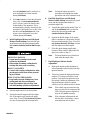
Before Starting
Oil & Fuel
THIS ENGINE IS CERTIFIED TO OPERATE
ON UNLEADED GAS AND OIL MIXTURE.
Note: BE SURE TO READ THESE
INSTRUCTIONS CAREFULLY
BEFORE ATTEMPTING TO START
OR OPERATE THIS UNIT. Using old
or improper oil or fuel, or improperly
mixing the oil and fuel can cause
engine damage. This type of damage
will void the engine warranty.
POTENTIAL HAZARD
• In certain conditions gasoline is extremely
flammable and highly explosive.
WHAT CAN HAPPEN
• A fire or explosion from gasoline can burn
you, others, and cause property damage.
HOW TO AVOID THE HAZARD
• Use a funnel and fill the fuel tank outdoors,
in an open area, when the engine is cold.
Wipe up any gasoline that spills.
• Do not fill the fuel tank completely full.
Add gasoline to the fuel tank until the level
is 1/4” to 1/2” (6 mm to 13 mm) below the
bottom of the filler neck. This empty space
in the tank allows gasoline to expand.
• Never smoke when handling gasoline, and
stay away from an open flame or where
gasoline fumes may be ignited by a spark.
• Store gasoline in an approved container
and keep it out of the reach of children.
• Never buy more than a 30-day supply of
gasoline.
Recommended Oil Type
An 8 oz. (0.24 liter) bottle of 2-cycle engine oil is
included with your product.
TORO 2-cycle oil is recommended for this outdoor
power tool. If another brand of 2-cycle oil is used,
make sure it is high quality oil, formulated for
2-cycle, air-cooled engines.
POTENTIAL HAZARD
• Gasoline/oil mixture contains petroleum
distillate.
WHAT CAN HAPPEN
• Gasoline/oil mixture can be harmful or
fatal if swallowed. It can also irritate your
skin.
HOW TO AVOID THE HAZARD
• Do not drink gasoline/oil mixture.
• Avoid prolonged contact with skin. Wash
thoroughly after handling.
• Do not reuse oil bottle.
IMPORTANT: If gasoline/oil mixture is
swallowed, do not induce vomiting. CALL
PHYSICIAN IMMEDIATELY.
Recommended Fuel Type
Use clean, fresh, unleaded gasoline that is less than
60 days old.
Note: Alcohol blended fuel absorbs moisture
(water). As little as 1% moisture in the
fuel can cause fuel and oil to separate
and form acids when stored.
If this type of fuel must be used, use
fresh fuel, (less than 60 days old) and
mix according to the mixing
instructions.
Definition Of Blended Fuels
Today’s fuels are often a blend of gasoline and one or
more oxygenates such as ethanol, methanol or MTBE
(ether).
Use Of Blended Fuels
If you choose to use a blended fuel or its use is
unavoidable, the following precautions are
recommended.

EN–8
1. Always use fresh fuel mix per your operator’s
manual.
2. Use a special additive such as Toro Gas
Stabilizer/Conditioner, STA-BILr or an
equivalent.
3. Always agitate the fuel mix before fueling the
unit.
4. Drain the tank and run the engine dry before
storing the unit.
Use Of Fuel Additives
The use of fuel additive, such as Toro Gas
Stabilizer/Conditioner, STA-BILr Gas Stabilizer or
an equivalent, will inhibit corrosion and minimize the
formation of gum deposit. Add 0.8 oz (23 ml) per
gallon of fuel per instructions on container. NEVER
add fuel additives directly to the unit’s fuel tank.
Using a fuel additive can keep fuel fresh for up to
six (6) months.
Mixing Oil And Fuel
Note: For proper engine operation and
maximum reliability, pay strict
attention to the oil and fuel mixing
instructions on the 2-cycle oil
container. Use a 32:1 fuel/oil ratio
when you use 2-cycle oil. Using
improperly mixed fuel can severely
damage the engine.
Thoroughly mix the proper ratio of 2-cycle engine oil
with unleaded gasoline in a separate fuel can, 32:1.
Do not mix them directly in the engine fuel tank. See
the table below for specific gas and oil mixing
ratios.
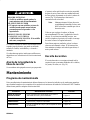
32:1 GAS/OIL Mixing Chart
POTENTIAL HAZARD
• Gasoline contains gasses that can build up
pressure inside a gas tank.
WHAT CAN HAPPEN
• Fuel can be sprayed on you when removing
gas cap.
HOW TO AVOID THE HAZARD
• Remove fuel cap slowly to avoid being
sprayed with fuel.
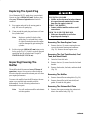
Operation
Starting/Stopping
1. Mix oil with gas and fill fuel tank with fuel/oil
mixture — per instructions on page 8.
2. Put the ignition switch in the “on” position. See
Fig. 10 for the location of the ON/OFF
SWITCH.
3. Fully press and release the primer bulb 5 to 7
times. See Fig. 11 for the primer bulb location.
4. Place the choke lever in the full “choke”
position. See Fig. 11.
5. With the unit on the ground, squeeze the throttle
trigger fully and pull the starter rope briskly
(Fig. 12) until the engine sounds like it wants to
run. (Normally 2 to 5 pulls).
6. Place the choke lever in the “partial” choke
position (fig. 11). pull the starter rope briskly 1
to 3 times to start the engine (Fig. 12).
7. If the engine does not start, repeat steps 4
through 6.
8. After the engine warms up for 5 to 10 seconds,
place the choke lever in the “run” position
(Fig. 11).
9. To stop the engine, put the ignition switch in the
“off” position (Fig. 10).

EN–9
Note: When storing the unit or when setting
unit down between uses, place the unit
flat on the floor so it sits on its stand
instead of hanging it by the guard or
the cutting head (Fig. 13).
Using The Brush Blade
Note: Always use the shoulder harness when
using the brush blade accessory.
1. Always maintain the proper stance for using the
brush blade kit (Fig. 14).
Sharpening The Brush Blade
IMPORTANT: Do not sharpen the brush
blade.
POTENTIAL HAZARD
• Sharpening the blade can cause the blade
tip to break off while in use.
WHAT CAN HAPPEN
• Contact with a thrown blade or piece of
blade could result in serious personal
injury to operator or bystanders.
HOW TO AVOID THE HAZARD
• DO NOT SHARPEN THE BRUSH
BLADE. Replace blade if dull.
The brush blade is designed with a second set of
teeth, which can be used by removing the blade,
turning it upside down, and reinstalling it.
If a crack is noticed, install a new blade from your
Authorized Toro Service Dealer.
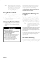
Adjusting The Trimming Line
Length
Your trimmer is equipped with a bump head that
allows the operator to release more trimming line
without stopping the engine. To release additional
line, lightly tap the trimming head on the ground
(Fig. 15) while operating the trimmer at high speed.
Note: Always keep the trimming line fully
extended. Line release becomes more
difficult as cutting line becomes
shorter.
Each time the head is bumped, about 1 in (25.4 mm)
of trimming line is released. A blade in the string
guard will cut the line to the proper length if excess
line is released.
For best results, tap the head on bare ground or hard
soil. If line release is attempted in tall grass, the
engine may stall.
Decorative Trimming
Decorative trimming is accomplished by removing all
vegetation around trees, posts, fences, etc (Fig. 16).
La page charge ...
La page charge ...
La page charge ...
La page charge ...
La page charge ...
La page charge ...
La page charge ...
La page charge ...
La page charge ...
La page charge ...
La page charge ...
La page charge ...
La page charge ...
La page charge ...
La page charge ...
La page charge ...
La page charge ...
La page charge ...
La page charge ...
La page charge ...
La page charge ...
La page charge ...
La page charge ...
La page charge ...
La page charge ...
La page charge ...
La page charge ...
La page charge ...
La page charge ...
La page charge ...
La page charge ...
La page charge ...
La page charge ...
La page charge ...
La page charge ...
La page charge ...
La page charge ...
La page charge ...
La page charge ...
La page charge ...
La page charge ...
La page charge ...
La page charge ...
La page charge ...
La page charge ...
La page charge ...
La page charge ...
La page charge ...
La page charge ...
La page charge ...
La page charge ...
La page charge ...
La page charge ...
La page charge ...
La page charge ...
La page charge ...
La page charge ...
La page charge ...
La page charge ...
La page charge ...
-
 1
1
-
 2
2
-
 3
3
-
 4
4
-
 5
5
-
 6
6
-
 7
7
-
 8
8
-
 9
9
-
 10
10
-
 11
11
-
 12
12
-
 13
13
-
 14
14
-
 15
15
-
 16
16
-
 17
17
-
 18
18
-
 19
19
-
 20
20
-
 21
21
-
 22
22
-
 23
23
-
 24
24
-
 25
25
-
 26
26
-
 27
27
-
 28
28
-
 29
29
-
 30
30
-
 31
31
-
 32
32
-
 33
33
-
 34
34
-
 35
35
-
 36
36
-
 37
37
-
 38
38
-
 39
39
-
 40
40
-
 41
41
-
 42
42
-
 43
43
-
 44
44
-
 45
45
-
 46
46
-
 47
47
-
 48
48
-
 49
49
-
 50
50
-
 51
51
-
 52
52
-
 53
53
-
 54
54
-
 55
55
-
 56
56
-
 57
57
-
 58
58
-
 59
59
-
 60
60
-
 61
61
-
 62
62
-
 63
63
-
 64
64
-
 65
65
-
 66
66
-
 67
67
-
 68
68
-
 69
69
-
 70
70
-
 71
71
-
 72
72
-
 73
73
-
 74
74
-
 75
75
-
 76
76
-
 77
77
-
 78
78
-
 79
79
-
 80
80


Toro 18" Brush Cutter Manuel utilisateur
- Catégorie
- Outils de jardin
- Taper
- Manuel utilisateur
dans d''autres langues
- English: Toro 18" Brush Cutter User manual
- español: Toro 18" Brush Cutter Manual de usuario
Documents connexes
Autres documents
-
Powermate PWST4317EAR Manuel utilisateur
-
Cub Cadet ST 228 Manuel utilisateur
-
MTD 41ADY90C401 Le manuel du propriétaire
-
Yard Machines Y780 Manuel utilisateur
-
 Yardworks hs720r Manuel utilisateur
-
Southland PWST4317EAR Manuel utilisateur
-
-
