
© 2000 Sony Corporation
4-650-926-18(1)
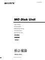
User’s Guide
Mode d’emploi
Bedienungsanleitung
Guía del usuario
Istruzioni per l’uso
RMO-S561
MO Disk Unit

2
Owner’s Record
The model and serial numbers are located on the
bottom of the unit. Record the serial number in
the space provided below.
Refer to them whenever you call upon your Sony
dealer regarding this product.
Model No. RMO-S561
Serial No._________________________
Information
For the customer in the U.S.A.
You are cautioned that any changes or
modifications not expressly approved in this
manual could void your authority to operate this
equipment.
This equipment has been tested and found to
comply with the limits for a Class B digital
device, pursuant to Part 15 of the FCC Rules.
These limits are designed to provide reasonable
protection against harmful interference in a
residential installation. This equipment generates,
uses, and can radiate radio frequency energy and,
if not installed and used in accordance with the
instructions, may cause harmful interference to
radio communications. However, there is no
guarantee that interference will not occur in a
particular installation. If this equipment does
cause harmful interference to radio or television
reception, which can be determined by turning
the equipment off and on, the user is encouraged
to try to correct the interference by one or more
of the following measures:
–Reorient or relocate the receiving antenna.
–Increase the separation between the equipment
and receiver.
–Connect the equipment into an outlet on a
circuit different from that to which the receiver
is connected.
–Consult the dealer or an experienced radio/TV
technician for help.
This device requires shielded interface cables to
comply with FCC emission limits.
Safety Regulations
If you have any questions about this product, you
may call: Sony Customer Information Center 1-
800-352-SONY(7669) or write to: Sony
Customer Information Center 3300 Zanker Road,
San Jose, CA 95134.
Declaration of Conformity
Trade Name: SONY
Model No.: RMO-S561
Responsible Party: Sony Electronics Inc.
Address: 16530 Via Esprillo,
San Diego,
CA 92127 U.S.A.
Telephone No.: 858-942-2230
This device complies with Part 15 of the FCC
Rules. Operation is subject to the following two
conditions: (1) This device may not cause
harmful interference, and (2) This device must
accept any interference received, including
interference that may cause undesired operation.

3
WARNING
To reduce the risk of fire or electric
shock, do not expose this apparatus to
rain or moisture.
To avoid electrical shock, do not open the
cabinet. Refer servicing to qualified
personnel only.
CAUTION
As the laser beam used in the RMO-S561 is
harmful to the eyes, do not attempt to
disassemble the unit.
Refer servicing to qualified personnel only.
The use of controls or adjustments or
performance of procedures other than those
specified herein may result in hazardous
radiation exposure.
This label is affixed inside the unit.
CLASS 3B LASER RADIATION WHEN OPEN.
AVOID DIRECT EXPOSURE TO THE BEAM.
RADIATIONS LASER DE CLASSE 3B EN CAS D'OUVERTURE.
EVITER TOUTE EXPOSITION DIRECTE AU FAISCEAU.
KLASSE 3B LASERSTRAHLUNG WENN GEÖFFNET.
DIREKTEN KONTAKT MIT DEM STRAHL VERMEIDEN.
LASERSTRÅLING AF KLASSE 3B VED ÅBNING.
UNDGÅ DIREKTE UDSÆTTELSE FOR STRÅLING.
LASERSTRÅLING I KLASSE 3B NÅR DEKSEL ÅPNES.
UNNGÅ DIREKTE EKSPONERING FOR STRÅLEN.
KLASS 3B LASERSTRÅLNING NÄR DENNA DEL ÄR ÖPPNAD.
UNDVIK ATT DIREKT EXPONERA DIG FÖR STRÅLNINGEN.
AVATTUNA LUOKAN 3B LASERSÄTEILYÄ.
VÄLTÄ SUORAA ALTISTUMISTA SÄTEELLE.
CAUTION
ATTENTION
VORSICHT
ADVARSEL
ADVARSEL
VARNING
VARO!
This MO disk unit is classified as a CLASS 1
LASER PRODUCT.
The CLASS 1 LASER PRODUCT
label is located on the bottom exterior.
CLASS 1
LASER PRODUCT
LASER KLASSE 1
PRODUKT
LUOKAN 1 LASERLAITE
KLASS 1 LASER APPARAT
English
NOTICE
Use the power cord set approved by the
appropriate testing organization for the
specific countries where this unit is to be used.
CAUTION
The mains plug on this equipment must be
used to disconnect mains power.
Please ensure that the socket outlet is installed
near the equipment and shall be easily
accessible.
Disposal of Old Electrical & Electronic
Equipment (Applicable in the European
Union and other European countries with
separate collection systems)
This symbol on the product or on its
packaging indicates that this product
shall not be treated as household
waste. Instead it shall be handed over
to the applicable collection point for
the recycling of electrical and
electronic equipment. By ensuring this product is
disposed of correctly, you will help prevent
potential negative consequences for the
environment and human health, which could
otherwise be caused by inappropriate waste
handling of this product. The recycling of
materials will help to conserve natural resources.
For more detailed information about recycling of
this product, please contact your local Civic
Office, your household waste disposal service or
the shop where you purchased the product.
According to the EU Directives related to
product safety, EMC and R&TTE the
manufacturer of this product is Sony
Corporation, 6-7-35 Kitashinagawa
Shinagawa-ku Tokyo, 141-0001 Japan.
The Authorised Representative is Sony
Deutschland GmbH, Hedelfinger Strasse
61,70327 Stuttgart, Germany.
For any service or guarantee matters please
refer to the addresses given in separate service
or guarantee documents.

4
Table of Contents
Using this Guide........................................ 5
Chapter 1 Introduction
Overview .................................................... 6
Features ....................................................... 6
Compatible Disks ....................................... 7
System Configuration ................................. 8
Location and Function of Parts ............... 9
Chapter 2 Getting Started
Component and Accessory Check List 10
Connecting the Disk Unit ....................... 11
Setting the SCSI ID.................................. 11
Setting the Disk Unit’s Functions .......... 12
Chapter 3 Using the Disk Unit
Inserting a Disk Cartridge ...................... 13
Ejecting a Disk Cartridge........................ 14
Chapter 4 Precautions
On the Disk Unit ...................................... 15
Safety Considerations ............................... 15
Damage Prevention .................................. 15
On the Disk Cartridges ........................... 16
Other Points Requiring Attention ............. 16
Protecting Your Data ................................ 17
Cleaning ................................................... 17
Cleaning a Disk ........................................ 17
Appendix
Specifications .......................................... 18
Disk Unit .................................................. 18
Optional Accessories ................................ 19

5
Using this Guide
This guide covers the use and operation of the
RMO-S561 Magneto-Optical Disk Unit (called
the “disk unit” thereafter). Do not attempt to use
the disk unit without first carefully reading this
guide. When finished, keep it handy for future
reference.
The guide is divided into the following sections.
Chapter 1 Introduction
This chapter contains a general overview of the
RMO-S561 disk unit, touching upon its features,
system configuration, and the location and
function of its parts.
Chapter 2 Getting Started
This chapter explains how to connect the disk
unit to the host computer and other SCSI
peripheral devices. It also explains how to set the
disk unit’s functions and the SCSI ID. Refer to
this chapter when setting up the disk unit.
Chapter 3 Using the Disk Unit
In this chapter, you learn how to turn on the disk
unit, and how to insert and eject a disk cartridge.
Refer to this chapter when you are ready to
actually begin using the disk unit.
Chapter 4 Precautions
This chapter contains precautions regarding the
use and operation of the disk unit and magneto-
optical disk cartridges.
It also discusses cleaning of disks.
Be sure to refer to this chapter before using the
disk unit.
Appendix
The Appendix contains an explanation of the disk
unit’s main specifications.
Notes
• The manufacturer disclaims all responsibility
for any losses incurred through malfunction or
use of this product.
• The manufacturer does not warrant the security
of data stored using this product. To guard
accidental data loss, frequent backup of
important data is highly recommended.
• Reproduction of the contents of this manual, in
whole or in part, is prohibited.
•Macintosh is a registered trademark of Apple
Computer, Inc.
•Microsoft and Windows are registered
trademarks of Microsoft Corporation.

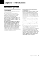
6 Chapter 1 Introduction
Chapter 1 Introduction
Overview
Features
The RMO-S561 Magneto-Optical Disk Unit has
the following features:
•Magneto-optical technology enables repeated
writing and erasing of data on the disk.
• The disk unit automatically senses the type of
disk being inserted, enabling the free use of
both 650 Mbytes (594 Mbytes), 1.3 Gbytes (1.2
Gbytes), 2.6 Gbytes (2.3 Gbytes), 5.2 Gbytes
(4.8 Gbytes, 4.1 Gbytes), and 9.1 Gbytes (8.6
Gbytes) disks indifferently.
•A maximum of 9.1 Gbytes (4,096 bytes/sector),
8.6 Gbytes (2,048 bytes/sector), 9.1 Gbytes
(1,024 bytes/sector), or 9.1 Gbytes (512 bytes/
sector) of data can be written on the two sides
of a 5.25-inch magneto-optical disk. This is
equivalent to about 6100–6500 times the
capacity of a conventional 3.5-inch floppy disk
(2HD).
• Any disk conforming to the internationally
accepted CCS (continuous/composite servo) or
CCW (continuous composite write-once) format
can be used in this disk unit.
• This disk unit employs SCSI-2 (Small
Computer System Interface-2).
• The 3,000 min
-1
(rpm) high-speed
spindle motor enables data transfer rates of
3.07 – 6.14 Mbytes/s (4,096 bytes/sector),
2.87 – 5.84 Mbytes/s (2,048 bytes/sector),
3.07 – 6.14 Mbytes/s (1,024 bytes/sector), or
3.07 – 6.14 Mbytes/s (512 bytes/sector).
•With disk capacities under 5.2 Gbytes (4.8
Gbytes, 4.1 Gbytes), the spindle motor rotates at
3300 min
-1
(rpm).
•With disk capacities under 2.6 Gbytes (2.3
Gbytes), the spindle motor rotates at 3600 min
-1
(rpm).
• The low-profile, light-weight optical pick-up
yields average seek times of 25ms.
• Use of a highly reliable error correction code
(ECC) system keeps the error rate as low as
10
-12
.
• Optimum operation environment is provided
through use of a large, 8MB buffer and
optimized cache control algorithm. (Write cache
can be enabled or disabled. For details, see
“Setting the Disk Unit’s Functions” on page
12.)

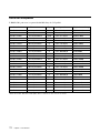
Chapter 1 Introduction 7
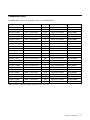
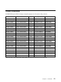
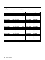
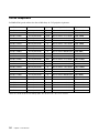
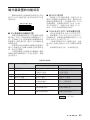
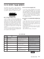
Compatible Disks
The RMO-S561 can use the following Sony 5.25-inch MO Disks:
Standard Sector format Type* Capacity Sony equivalent
ISO/IEC 15286 2048 bytes/sector R/W About 5.2 G bytes EDM-5200B
ISO/IEC 15286 1024 bytes/sector R/W About 4.8 G bytes EDM-4800B
ISO/IEC 15286 512 bytes/sector R/W About 4.1 G bytes EDM-4100B
ISO/IEC 14517 1024 bytes/sector R/W About 2.6 G bytes EDM-2600B
ISO/IEC 14517 512 bytes/sector R/W About 2.3 G bytes EDM-2300B
ISO/IEC 13549 1024 bytes/sector R About 1.3 G bytes EDM-1300B
ISO/IEC 13549 512 bytes/sector R About 1.2 G bytes EDM-1200B
ISO/IEC 10089 1024 bytes/sector R About 650 M bytes EDM-650B
ISO/IEC 10089 512 bytes/sector R About 600 M bytes EDM-600B
ISO/IEC 15286 2048 bytes/sector WO About 5.2 G bytes CWO-5200B
ISO/IEC 15286 1024 bytes/sector WO About 4.8 G bytes CWO-4800B
ISO/IEC 15286 512 bytes/sector WO About 4.1 G bytes CWO-4100B
ISO/IEC 14517 1024 bytes/sector WO About 2.6 G bytes CWO-2600B
ISO/IEC 14517 512 bytes/sector WO About 2.3 G bytes CWO-2300B
ISO/IEC 13549 1024 bytes/sector R About 1.3 G bytes CWO-1300B
ISO/IEC 13549 512 bytes/sector R About 1.2 G bytes CWO-1200B
ISO/IEC 11560 1024 bytes/sector R About 650 M bytes CWO-650B
ISO/IEC 11560 512 bytes/sector R About 600 M bytes CWO-600B
ISO/IEC 22092 4096 bytes/sector R/W About 9.1 G bytes EDM-9100B
ISO/IEC 22092 2048 bytes/sector R/W About 8.6 G bytes EDM-8600B
ISO/IEC 22092 1024 bytes/sector R/W About 9.1 G bytes EM1-9100B
ISO/IEC 22092 512 bytes/sector R/W About 9.1 G bytes EM5-9100B
ISO/IEC 22092 4096 bytes/sector WO About 9.1 G bytes CWO-9100B
ISO/IEC 22092 2048 bytes/sector WO About 8.6 G bytes CWO-8600B
*R/W:Rewritable, R/W:Rewritable(MO), WO:Write Once, R:Read Only

8 Chapter 1 Introduction
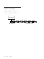
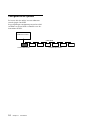
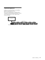
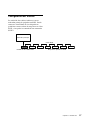
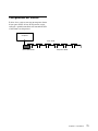
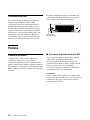
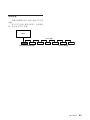
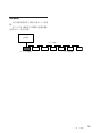
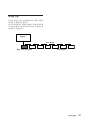
System Configuration
The disk unit should be used with a host
computer equipped with SCSI.
A maximum of seven peripheral devices can be
linked in a daisy chain on the SCSI bus, and
controlled with SCSI-2 commands.
Host computer
SCSI cable
RMO-S561 disk unit SCSI peripheral devices

Chapter 1 Introduction 9
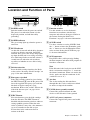
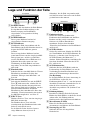
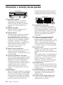
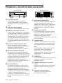
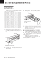
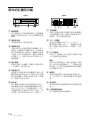
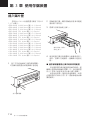
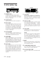
Location and Function of Parts
Front Panel
EJECT
POWER
BUSY
1
23
456
1 POWER switch
Push the button to turn the power on and off.
The power is on when the button is in the
depressed position, and off when fully
protruding.
2 POWER indicator
The green lamp lights up when the power is
turned on.
3 BUSY indicator
As this disk is inserted and the drive becomes
ready for read/write operation, the BUSY
indicator turns green. The orange lamp lights
up when the disk unit is accessing or writing
data. This lamp flashes on and off at about 2-
second intervals when the unit overheats,
regardless of whether or not a disk is being
accessed.
4 Disk insertion slot
Insert the disk cartridge into this slot. Refer
to the section “Inserting a Disk Cartridge” on
page 13 for more information.
5 Emergency eject hole
If the disk cartridge cannot be ejected using
the EJECT button 6, turn off the power and
insert the supplied emergency eject tool into
this hole to trip the emergency eject
mechanism. Refer to the section “What to do
if the disk does not eject” on page 14 for
further details.
6 EJECT button
Press this button to eject the disk cartridge
from the disk unit. The EJECT button is
disabled with the function switch or software
settings prohibit ejection. When the write
cache is enabled, it may take a few moments
(up to 45 seconds) for the disk to eject
because data in the cache must first be
written to the disk.
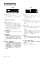
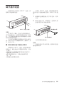
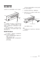
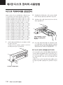
Rear Panel
A
1
BCDEFGH
0
SCSI CONNECTOR
AC IN
F.GND
SCSI ID
123 4 56
1 Function switches
Use this switches to set the disk unit’s
functions in accordance with the host
computer and software being used. Refer to
the section“Setting the Disk Unit’s
Functions” on page 12 for more information.
2 SCSI ID switch
Use these switches to set the SCSI ID. Push
the “–” button to lower the ID number; push
the “+” button to raise the ID number. Refer
to the section“Setting the SCSI ID”on page
11 for more information.
3 SCSI connectors
Plug SCSI cables (sold separately) linking
the host computer and other SCSI peripherals
into these connectors.
Note
If the disk unit is the last device on the SCSI
chain, set function switch F to “1” to turn on
the internal terminator. When it is not the last
device, make sure that the terminator is off
(switch F is set to “0”).
4 Air duct
The air for cooling the disk unit flows
through this duct, so be careful not to block
its surface or impede the outflow.
5 F.GND (frame ground) terminal
Connect the ground terminals of other
devices to the disk unit’s frame ground.
6 AC IN (AC power) connector
Connect the supplied AC power cord to this
connector.

10 Chapter 2 Getting Started
Chapter 2 Getting Started
Before setting up your RMO-S561 Magneto-
Optical Disk Unit, check to see that you have all
the required components and accessories. Then,
connect the disk unit to the host computer and
any other SCSI peripherals you may be using.
After checking to see that all the connections
have been properly made, set the SCSI ID using
the SCSI ID switch and the disk unit’s functions
using the function switches.
Note
Please refer to the installation manual included in
the device driver’s package for instructions when
using this device with a Macintosh
®
computer or
a computer running under Windows
®
system. For
questions concerning the device drivers, please
contact the device driver manufacturer as
indicated in the device driver package.
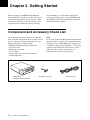
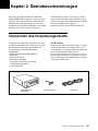
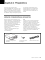
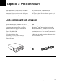
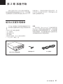
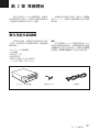
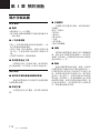
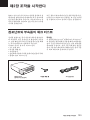
Component and Accessory Check List
Upon opening the carton, check to see that you
have all of the components and accessories listed
below. Contact your dealer immediately if you
find any missing or damaged items.
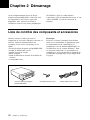
•RMO-S561 Magneto-Optical Disk Unit
• AC power cord
• Emergency eject tool
• User’s Guide
• Guide to Safe Use (Safety Precautions)
•1 Blank MO disk
RMO-S561 Emergency eject tool AC Power cord
Magneto-Optical Disk Unit

Chapter 2 Getting Started 11
You can hook up a maximum of seven SCSI
peripheral devices to a single host computer
through its SCSI bus.
Use the following Sony SCSI cable (sold
separately) to connect the disk unit.
Notes
• Before connecting the disk unit, be sure to turn
off the disk unit and all other devices on the
SCSI chain.
• If the disk unit is the last device on the SCSI
chain, set the function switch F on the rear
panel to “1” to turn on the internal terminator.
When it is not the last device, make sure that the
terminator is off (function switch F is set to
“0”).
• The total length of the SCSI cables connected to
a SCSI chain must not exceed six meters (19
feet 8
1
/4 inches).
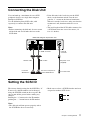
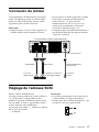
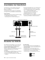
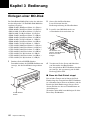
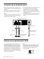
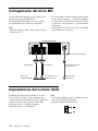
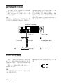
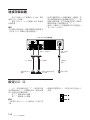
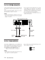
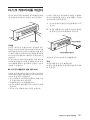
Connecting the Disk Unit
A
1
BCDEF GH
0
SCSI CONNECTOR
AC IN
F.GND
SCSI ID
Setting the SCSI ID
to SCSI connector
to AC IN
connector
AC power cord
(supplied)
SCSI-2 cableSCSI-2 cable
to another
SCSI device
to the host computer or
another SCSI device
to an AC outlet
RMO-S561 Magneto-Optical Disk Unit
The factory default setting for the SCSI ID is “0.”
If necessary, this ID number can be changed
using the SCSI ID switch on the rear panel. Be
sure to turn off the power before making any
changes.
Pushing the “+” button raises the ID number;
pushing the “–” button lowers the ID number.
Notes
• The disk unit will not operate properly unless
the SCSI ID has been set correctly.
•Make sure to select a SCSI ID that has not been
assigned to another SCSI device.
0

12 Chapter 2 Getting Started
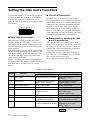
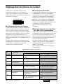
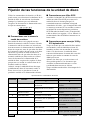
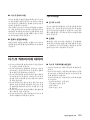
Setting the Disk Unit’s Functions
Use function switches (A – H) on the rear panel
to select the disk unit’s functions in accordance
with the host computer and software you are
using. Be sure to turn off the power before setting
the switches.
A
1
BCDEFGH
0
■ Write Cache Precautions
This disk unit is equipped with a write cache
function. When the write cache is enabled, never
turn off the disk unit power without making sure
that all data has been written to the disk from the
cache memory.
Data will be lost if you turn off the power before
all data in cache memory has been written to the
disk. Before turning off the disk unit power, be
sure to eject the disk, as this writes data from
cache memory to the disk.
Further, even though the drive will periodically
flush data from cache memory periodically to the
disk, data may be lost in the case of a power
failure.
■ Ultra SCSI Precautions
Using the Ultra SCSI function requires that an
Ultra SCSI cable be used to connect the disk unit
and the host system. It is recommended that the
cumulative cable length be minimized, and that
the cable length be kept under 3 m in length
when connecting up to four SCSI peripheral
devices. In all other cases, the total length of the
cable should not exceed 1.5 m. Further, the SCSI
bus termination should be well maintained.
■ Precautions for Handling the 1024
and 512 bytes/sector
Note that this drive uses a sector size of 4096
bytes/sector. If you insert a disk with a sector size
of 1024 or 512 bytes/sector, the drive internally
converts the sector size of software to emulate a
sector size of 4096 bytes/sector.
Further, data already written to the disk may be
lost if the power is accidentally turned off while
data is being written to the disk.
Be careful when operating the power switch.
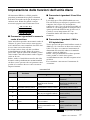
Function Switch Settings
Switch Function
10
A Parity check SCSI parity check is disabled. SCSI parity check is
enabled.
B Device type Peripheral device type 00H Peripheral device type 07H
(Direct Access Device) (Optical Memory Device)
C Write cache control Disable write cache. Enable write cache.
D Ultra SCSI control Ultra SCSI compatible Not Ultra SCSI compatible
E Force verify All write operations are verfied. All write operations are
(with a verify pass) normal operations.
(without a verify pass)
F Terminator The internal terminator is on. The internal terminator is off.
G Auto spin up Inserting a disk does not causes Inserting a disk causes
the spindle motor to rotate. the spindle motor to rotate.
H Manual eject Disk catridge cannot be ejected Disk cartridge can be
by pressing the EJECT button. ejected by pressing the
EJECT button
: Factory setting

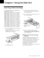
Chapter 3 Using the Disk Unit 13
Use the following Sony 5.25-inch MO disks in
your RMO-S561 disk unit.
• EDM-9100B (4,096 bytes/sector, 9.1 Gbytes)
• EDM-8600B (2,048 bytes/sector, 8.6 Gbytes)
•EM1-9100B (1,024 bytes/sector, 9.1 Gbytes)
•EM5-9100B (512 bytes/sector, 9.1 Gbytes)
• EDM-5200B (2,048 bytes/sector, 5.2 Gbytes)
• EDM-4800B (1,024 bytes/sector, 4.8 Gbytes)
• EDM-4100B (512 bytes/sector, 4.1 Gbytes)
• EDM-2600B (1,024 bytes/sector, 2.6 Gbytes)
• EDM-2300B (512 bytes/sector, 2.3 Gbytes)
•CWO-9100B (4,096 bytes/sector, 9.1 Gbytes )
•CWO-8600B (2,048 bytes/sector, 8.6 Gbytes)
•CWO-5200B (2,048 bytes/sector, 5.2 Gbytes )
•CWO-4800B (1,024 bytes/sector, 4.8 Gbytes)
•CWO-4100B (512 bytes/sector, 4.1 Gbytes)
•CWO-2600B (1,024 bytes/sector, 2.6 Gbytes )
•CWO-2300B (512 bytes/sector, 2.3 Gbytes)
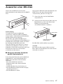
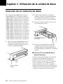
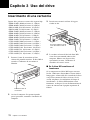
1 Press the POWER switch located on the left
side of the front panel.
This turns on the disk unit and causes the
POWER indicator to light up.
Chapter 3 Using the Disk Unit
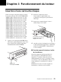
Inserting a Disk Cartridge
2 Start up the host computer. Refer to the
manual supplied with the host computer for
the start up procedure.
3 Insert a disk cartridge with the side you want
to use facing upwards.
4 Access or write data on the disk using
software commands on the host computer.
The BUSY indicator lights up while the unit
is accessing the disk.
■ What to do if the disk unit stops
operating
When the temperature in the disk unit exceeds
the preset level, the BUSY indicator starts
flashing on and off at about 2-seconds intervals,
regardless of whether or not a disk is being
accessed, and the disk unit stops operating.
If this happens, you should improve the
ventilation of a setting area.
If the disk unit still refuses to operate, unplug the
unit and contact your dealer.
To use Side A, insert the
disk with “A” facing
upward.
Press the POWER switch

14 Chapter 3 Using the Disk Unit
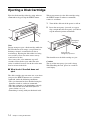
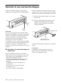
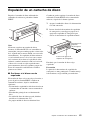
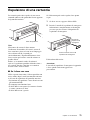
Ejecting a Disk Cartridge
Eject the disk cartridge either by using software
commands or by pressing the EJECT button.
Note
Do not attempt to eject a disk cartridge while the
BUSY indicator is lit orange (except when it is
flashing at about 2-second intervals due to
overheating). Ejecting the disk while it is being
accessed may cause data write errors or may
result in loss of data.
Also, it may take a few moments (up to 45
seconds) for the disk to eject when the write
cache is enabled, because data in the cache must
first be written to the disk.
■ What to do if the disk does not
eject
The disk cartridge may not come out, even when
you press the EJECT button or use a software
command, under the following conditions:
• The eject function has been disabled using the
function switch or a software command;
• The host computer is not functioning properly;
• The disk unit has been turned off (due to a
power failure, etc.); or
• Something is wrong with your disk unit itself.
When you cannot eject the disk cartridge using
the EJECT button or software commands,
remove it as follows.
1 Turn off the disk unit if the power is still on.
2 Insert the emergency eject tool (or a paper
clip) straight into the emergency eject hole to
trip the manual ejection mechanism.
This should cause the disk cartridge to eject.
Caution
The tip of the emergency eject tool is sharp.
When handling the tool, please be careful to
avoid injury.
EJECT button
Emergency
eject Tool
Insert into the
emergency eject hole.

Chapter 4 Precautions 15
Chapter 4 Precautions
On the Disk Unit
Safety Considerations
■ Power supply
• Be sure to use 100 - 240V AC.
• Do not share the AC outlet with any other
power-consuming equipment such as copying
machines or shredders.
■ AC power cord
• Be careful not to place or drop heavy object on
the power cord, or subject it to anything that
may damage it.
•When unplugging the cord from an AC outlet,
be sure to grasp the plug itself. Pulling on the
cord may cause damage to the internal wiring.
• Unplug the unit when not using it for long
period of time.
■ Handling the emergency eject tool
The tip of the emergency eject tool is sharp.
When handling the tool, please be careful to
avoid injury. Do not use the tool for any purpose
other than ejecting disks.
Damage Prevention
■ Do not subject the disk unit to
shock or vibration
Dropping the unit or subjecting it to strong
impact may damage the disk unit.
■ Setting position
The disk unit is designed to be used in the
horizontal position. Do not position it at an angle.
■ Location requirements
Careful consideration should be given to the
following in selecting a site to install or store
your disk unit.
Avoid the following conditions:
• High humidity
• High temperatures
• Direct sunlight
• Dust
• Strong vibration
•Wide temperature fluctuations
■ Ventilation
Care should be exercised to prevent the internal
mechanisms of the disk unit from overheating.
Be careful not to clog or block the vent, or place
the unit in an area with poor ventilation. The disk
unit may stop operating altogether if the internal
temperature becomes too high.
■ Condensation
Avoid subjecting the disk unit to extremes in
temperature. If, for example, the disk unit is
moved suddenly from a very cold location to a
warm one, moisture from condensation may form
within the unit due to the quick rise in ambient
temperature. If a sudden change in the
temperature cannot be avoided, wait for an hour
or more before using the disk unit. Inserting a
disk cartridge into the mechanism when moisture
is present may cause damage to both the disk and
the disk unit. Remove the disk cartridge
immediately if you suspect any condensation
problems. The moisture should evaporate quickly
if the disk unit is left on without a disk inserted.

16 Chapter 4 Precautions
■ Moving the disk unit
Be sure to remove the disk cartridge when the
disk unit is not being used. Also never move or
transport the unit with the disk cartridge still
inserted.
While in operation, the disk rotates at a high
speed. Moving the disk unit at such a time may
disturb the spinning disk and cause it to be
damaged. Always remove the disk cartridge
before moving your disk unit.
■ If problems occur
If any problems occur, turn off the power and
unplug the disk unit, contact your dealer.
Other Points Requiring Attention
■ Electrical noise
The high-frequency signal generated by the disk
unit may cause interference or static on other
electrical appliances such as radios, televisions
and audio tuners. If this should occur, move the
disk unit a little farther away from the affected
appliance.
■ Maintenance
Clean the cabinet with a dry soft cloth, or with a
soft cloth lightly moistened with a mild detergent
solution. Do not use any type of solvent, such as
alcohol or benzine, which may damage the finish.
On the Disk Cartridges
• Do not drop the disk cartridge or subject it to
any violent shocks or vibration.
• Do not disassemble the disk cartridge. It is a
precision component and has been carefully
adjusted at the factory prior to shipment.
• Do not open the disk cartridge’s shutter
manually or touch the disk inside. The shutter is
designed to open automatically when the
cartridge is inserted into the disk unit.
• Do not use the cartridge under ambient
conditions of high humidity or wide
temperature fluctuations. Moisture from
condensation may make it impossible to read or
write data.
• Avoid inserting and ejecting the disk cartridge
more than is necessary.
• Always eject and remove the disk cartridge
from the disk unit after using it.
■ Storing disk cartridges
• Store the disk cartridges in their cases.
• Do not leave the cartridges exposed to direct
sunlight or excessive heat, like on the dashboard
or in the glove compartment of an automobile.
Do not store the disk cartridges under the
following conditions.
– Excessive dust and debris
– Exposure to direct sunlight
– Near a heat source
– High humidity

Chapter 4 Precautions 17
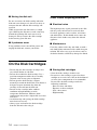
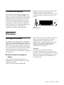
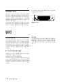
Protecting Your Data
The magneto-optical disk cartridges are equipped
with a DATA PROTECT switch (red tab) to
prevent accidental erasure of data on the disk or
inadvertent writing of unwanted data. Slide this
switch in the direction of the arrow as illustrated
below to enable the write protect function.
You can still read the data contained on the disk,
but will not be allowed to write on or erase the
disk. Return the switch to its original position to
disable the write protect.
Cleaning
DATA PROTECT
switch
Make it a practice to leave the write protection
enabled when you do not foresee the need to
write on the disk.
Cleaning a Disk
Dust and stains may accumulate on MO disks
when they are used for a long period of time. To
avoid resultant data read/write errors, use an
optional disk cleaner. To maintain the high
performance and prolong the useful life of your
MO disk, cleaning at least once every three
months is recommended.
■ Disk cleaning accessories
Use the following Sony disk cleaning kit or disk
cleaner (sold separately).
•MOA-D51 Disk Cleaning Kit
Do not use any other type of disk cleaner as it
may cause data read/write errors due to the
differences in disk surface characteristics. For
cleaning instructions, refer to the manual
supplied with each cleaning accessory.
Attention
In the disk unit, preventive measures are taken to
guard against dust. It is unnecessary to clean the
optical lens of your disk unit. Using a lens
cleaning cartridge may damage the disk unit.

18 Appendix
Appendix
Specifications
Disk Unit
■ Performance
Capacity
Per disk
9.1 Gbytes (ZCAV 4,096 bytes/sector)
8.6 Gbytes (ZCAV 2,048 bytes/sector)
9.1 Gbytes (ZCAV 1,024 bytes/sector)
9.1 Gbytes (ZCAV 512 bytes/sector)
5.2 Gbytes (ZCAV 2,048 bytes/sector)
4.8 Gbytes (ZCAV 1,024 bytes/sector)
4.1 Gbytes (ZCAV 512 bytes/sector)
2.6 Gbytes (ZCAV 1,024 bytes/sector)
2.3 Gbytes (ZCAV 512 bytes/sector)
Rotation speed
3,000 min
–1
(3,000 rpm)
3,300 min
–1
(3,300 rpm)
3,600 min
–1
(3,600 rpm)
Seek times (average)
25 ms (typical)
User data transfer rate
Continuous transfer rate
3.07 – 6.14 Mbytes/s
(4,096 bytes/sector)
2.87 – 5.84 Mbytes/s
(2,048 bytes/sector)
3.07 – 6.14 Mbytes/s
(1,024 bytes/sector)
3.07 – 6.14 Mbytes/s
(512 bytes/sector)
Burst transfer rate
20 Mbytes/s (using Ultra SCSI)
Host interface
SCSI-2 (Small Computer System Interface-2)
ANSI X3.131–1994
■ Operating environment
Installation
Horizontal (±5°)
Temperature
Operating
5 °C to 40 °C (41 °F to 104 °F)
(gradient 10° C/h or 18 °F/h)
Non-operating
– 30 °C to 60 °C (– 22 °F to 140 °F)
Relative humidity
Operating
10 % to 85 % (no condensation)
Non-operating
10 % to 90 %
■ Laser
Type
Semiconductor AlGaInP laser
Wavelength
661 nm ± 6 nm
Maximum output
40 mW CW
60 mW Pulse
■ Power supply and others
Power supply
100 – 240 V AC ±10%, 50/60 Hz ±5%
Current drain
0.60 – 0.35 A max
Maximum external dimensions (excluding
protruding parts and air duct)
211 × 70 × 293 mm (W/H/D)
(8
3
/8 × 2
7
/8 × 11
5
/8 inches)
Weight
4.9 kg (10.9 lb.)
Accessories
AC power cord (1)
Emergency eject tool (1)
User’s Guide (1)
MO Disk (1)
Formatting Utility (1)
Design and specifications are subject to change
without notice.

Appendix 19
Optional Accessories
MO disks
EDM-9100B (4,096 bytes/sector, 9.1 Gbytes)
EDM-8600B (2,048 bytes/sector, 8.6 Gbytes)
EM1-9100B (1,024 bytes/sector, 9.1 Gbytes)
EM5-9100B (512 bytes/sector, 9.1 Gbytes)
EDM-5200B (2,048 bytes/sector, 5.2 Gbytes)
EDM-4800B (1,024 bytes/sector, 4.8 Gbytes)
EDM-4100B (512 bytes/sector, 4.1 Gbytes)
EDM-2600B (1,024 bytes/sector, 2.6 Gbytes)
EDM-2300B (512 bytes/sector, 2.3 Gbytes)
Continuous composite write-once disks
CWO-9100B (4,096 bytes/sector, 9.1 Gbytes)
CWO-8600B (2,048 bytes/sector, 8.6 Gbytes)
CWO-5200B (2,048 bytes/sector, 5.2 Gbytes)
CWO-4800B (1,024 bytes/sector, 4.8 Gbytes)
CWO-4100B (512 bytes/sector, 4.1 Gbytes)
CWO-2600B (1,024 bytes/sector, 2.6 Gbytes)
CWO-2300B (512 bytes/sector, 2.3 Gbytes)
Disk Cleaning Kit
MOA-D51

20
AVERTISSEMENT
Afin de réduire les risques d’incendie ou
de choc électrique, n’exposez pas cet
appareil à la pluie ni à l’humidité.
Pour éviter toute électrocution, ne pas
ouvrir le boîtier. Confier l’entretien à un
technicien qualifié uniquement.
NOTICE
Utiliser le cordon d’alimentation approuvé par
l’organisation de contrôle appropriée pour les
pays auxquels le produit est destiné.
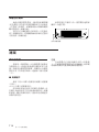
Règles de sécurité Sommaure
Comment utiliser ce Guide..................... 21
Chapitre 1 Introduction
Aperçu ...................................................... 22
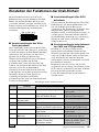
Caractéristiques ........................................ 22
Disques compatibles ................................. 23
Configuration de système ......................... 24
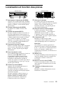
Localisation et fonction des pièces ...... 25
Chapitre 2 Démarrage
Liste de contrôle des composants et
accessoires ...................................... 26
Connexion du lecteur ............................. 27
Réglage de l’adresse SCSI ..................... 27
Réglage des fonctions du lecteur.......... 28
Chapitre 3 Fonctionnement du lecteur
Insertion d’une cartouche disque.......... 29
Ejection d’une cartouche disque ........... 30
Chapitre 4 Précautions
A propos du lecteur ................................ 31
Sécurité ..................................................... 31
Prévention des dommages ........................ 31
Autres points à prendre en compte ........... 32
A propos des cartouches disques ........ 32
Protection des données ............................. 33
Entretien................................................... 33
Nettoyage des disques .............................. 33
Appendice
Spécifications .......................................... 34
Lecteur ...................................................... 34
Accessoires en option ............................... 35
Traitement des appareils électriques et
électroniques en fin de vie (Applicable
dans les pays de l’Union Européenne et
aux autres pays européens disposant de
systèmes de collecte sélective)
Ce symbole, apposé sur le produit ou
sur son emballage, indique que ce
produit ne doit pas être traité avec les
déchets ménagers. Il doit être remis à
un point de collecte approprié pour le
recyclage des équipements électriques
et électroniques. En s’assurant que ce produit est
bien mis au rebut de manière appropriée, vous
aiderez à prévenir les conséquences négatives
potentielles pour l’environnement et la santé
humaine. Le recyclage des matériaux aidera à
préserver les ressources naturelles. Pour toute
information supplémentaire au sujet du recyclage
de ce produit, vous pouvez contacter votre
municipalité, votre déchetterie ou le magasin où
vous avez acheté le produit.
La page est en cours de chargement...
La page est en cours de chargement...
La page est en cours de chargement...
La page est en cours de chargement...
La page est en cours de chargement...
La page est en cours de chargement...
La page est en cours de chargement...
La page est en cours de chargement...
La page est en cours de chargement...
La page est en cours de chargement...
La page est en cours de chargement...
La page est en cours de chargement...
La page est en cours de chargement...
La page est en cours de chargement...
La page est en cours de chargement...
La page est en cours de chargement...
La page est en cours de chargement...
La page est en cours de chargement...
La page est en cours de chargement...
La page est en cours de chargement...
La page est en cours de chargement...
La page est en cours de chargement...
La page est en cours de chargement...
La page est en cours de chargement...
La page est en cours de chargement...
La page est en cours de chargement...
La page est en cours de chargement...
La page est en cours de chargement...
La page est en cours de chargement...
La page est en cours de chargement...
La page est en cours de chargement...
La page est en cours de chargement...
La page est en cours de chargement...
La page est en cours de chargement...
La page est en cours de chargement...
La page est en cours de chargement...
La page est en cours de chargement...
La page est en cours de chargement...
La page est en cours de chargement...
La page est en cours de chargement...
La page est en cours de chargement...
La page est en cours de chargement...
La page est en cours de chargement...
La page est en cours de chargement...
La page est en cours de chargement...
La page est en cours de chargement...
La page est en cours de chargement...
La page est en cours de chargement...
La page est en cours de chargement...
La page est en cours de chargement...
La page est en cours de chargement...
La page est en cours de chargement...
La page est en cours de chargement...
La page est en cours de chargement...
La page est en cours de chargement...
La page est en cours de chargement...
La page est en cours de chargement...
La page est en cours de chargement...
La page est en cours de chargement...
La page est en cours de chargement...
La page est en cours de chargement...
La page est en cours de chargement...
La page est en cours de chargement...
La page est en cours de chargement...
La page est en cours de chargement...
La page est en cours de chargement...
La page est en cours de chargement...
La page est en cours de chargement...
La page est en cours de chargement...
La page est en cours de chargement...
La page est en cours de chargement...
La page est en cours de chargement...
La page est en cours de chargement...
La page est en cours de chargement...
La page est en cours de chargement...
La page est en cours de chargement...
La page est en cours de chargement...
La page est en cours de chargement...
La page est en cours de chargement...
La page est en cours de chargement...
La page est en cours de chargement...
La page est en cours de chargement...
La page est en cours de chargement...
La page est en cours de chargement...
La page est en cours de chargement...
La page est en cours de chargement...
La page est en cours de chargement...
La page est en cours de chargement...
La page est en cours de chargement...
La page est en cours de chargement...
La page est en cours de chargement...
La page est en cours de chargement...
La page est en cours de chargement...
La page est en cours de chargement...
La page est en cours de chargement...
La page est en cours de chargement...
La page est en cours de chargement...
La page est en cours de chargement...
La page est en cours de chargement...
La page est en cours de chargement...
La page est en cours de chargement...
La page est en cours de chargement...
La page est en cours de chargement...
La page est en cours de chargement...
La page est en cours de chargement...
La page est en cours de chargement...
La page est en cours de chargement...
La page est en cours de chargement...
La page est en cours de chargement...
La page est en cours de chargement...
La page est en cours de chargement...
La page est en cours de chargement...
La page est en cours de chargement...
La page est en cours de chargement...
La page est en cours de chargement...
La page est en cours de chargement...
-
 1
1
-
 2
2
-
 3
3
-
 4
4
-
 5
5
-
 6
6
-
 7
7
-
 8
8
-
 9
9
-
 10
10
-
 11
11
-
 12
12
-
 13
13
-
 14
14
-
 15
15
-
 16
16
-
 17
17
-
 18
18
-
 19
19
-
 20
20
-
 21
21
-
 22
22
-
 23
23
-
 24
24
-
 25
25
-
 26
26
-
 27
27
-
 28
28
-
 29
29
-
 30
30
-
 31
31
-
 32
32
-
 33
33
-
 34
34
-
 35
35
-
 36
36
-
 37
37
-
 38
38
-
 39
39
-
 40
40
-
 41
41
-
 42
42
-
 43
43
-
 44
44
-
 45
45
-
 46
46
-
 47
47
-
 48
48
-
 49
49
-
 50
50
-
 51
51
-
 52
52
-
 53
53
-
 54
54
-
 55
55
-
 56
56
-
 57
57
-
 58
58
-
 59
59
-
 60
60
-
 61
61
-
 62
62
-
 63
63
-
 64
64
-
 65
65
-
 66
66
-
 67
67
-
 68
68
-
 69
69
-
 70
70
-
 71
71
-
 72
72
-
 73
73
-
 74
74
-
 75
75
-
 76
76
-
 77
77
-
 78
78
-
 79
79
-
 80
80
-
 81
81
-
 82
82
-
 83
83
-
 84
84
-
 85
85
-
 86
86
-
 87
87
-
 88
88
-
 89
89
-
 90
90
-
 91
91
-
 92
92
-
 93
93
-
 94
94
-
 95
95
-
 96
96
-
 97
97
-
 98
98
-
 99
99
-
 100
100
-
 101
101
-
 102
102
-
 103
103
-
 104
104
-
 105
105
-
 106
106
-
 107
107
-
 108
108
-
 109
109
-
 110
110
-
 111
111
-
 112
112
-
 113
113
-
 114
114
-
 115
115
-
 116
116
-
 117
117
-
 118
118
-
 119
119
-
 120
120
-
 121
121
-
 122
122
-
 123
123
-
 124
124
-
 125
125
-
 126
126
-
 127
127
-
 128
128
-
 129
129
-
 130
130
-
 131
131
-
 132
132
-
 133
133
-
 134
134
-
 135
135
-
 136
136


dans d''autres langues
- italiano: Sony RMO-S561 Manuale del proprietario
- English: Sony RMO-S561 Owner's manual
- español: Sony RMO-S561 El manual del propietario
- Deutsch: Sony RMO-S561 Bedienungsanleitung
Documents connexes
Autres documents
-
Yamaha CRW2100S Le manuel du propriétaire
-
Sun Microsystems STOREDGE T3 Manuel utilisateur
-
-
Pioneer DVD-U03S Manuel utilisateur
-
-
MAXDATA 700T Le manuel du propriétaire
-
-