
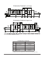
FT1000i-INDUSTRIAL WASHERS
LAVE-VAISSELLE INDUSTRIEL FT1000i
LAVAVAJILLAS INDUSTRIAL FT1000i
MODEL
MODÈLE
MODELO
FT1000i-IND
FT1000iS-IND
FT1000i-AIR
FT1000iS-AIR
701 S. RIDGE AVENUE
TROY, OHIO 45374-0001
937 332-3000
www.hobartcorp.com
F41210 (June 2020)

– 2 –
© HOBART 2020

– 3 –
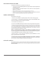
TABLE OF CONTENTS
OPERATION ..................................................................4
Machine Preparation – Check Before Beginning Operation ...........................4
Tank Filling .................................................................5
Washing ...................................................................6
Empty Strainer Baskets As Necessary ........................................7
Loading ................................................................7
Unloading ..............................................................7
Recommended Minimum Temperatures ..........................................7
Conveyor Speed Adjustment ...................................................8
High Pressure Blow Off (HPBO) System (If Equipped) ...............................8
Adjustable Rail System (If Equipped) ............................................8
CLEANING ..................................................................10
Deliming .................................................................. 11
Dos and Don'ts for Your New Hobart Dishwasher ..................................12
Curtain Congurations .......................................................13
PROGRAMMING ..............................................................15
Machine Operation and Programming Security Levels ..............................15
Operator – O ...........................................................15
SuperOperator – SO .....................................................15
Manager – M ..........................................................16
User Programming Instructions ................................................16
Menu Display Prompts .......................................................17
Entering the Manager Menu ..................................................17
About Screen ..............................................................17
Actions Menu ..............................................................18
Logs Menu ................................................................18
Operation Parameters Menu ..................................................19
MAINTENANCE ..............................................................22
Line Strainers ..............................................................22
Lubrication ................................................................22
Motors ................................................................22
Conveyor Gearmotor ....................................................22
Conveyor Drive Chain ...................................................22
Conveyor Take-Up Unit ..................................................23
High Pressure Blow Off (HPBO) System (If Equipped) ..............................23
Guards & Filters ........................................................23
Hoses & Clamps ........................................................23
Motor Mounting .........................................................23
Motor Shaft Lubrication ..................................................24
Air Filter Replacement ...................................................24
TROUBLESHOOTING .........................................................25

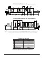
– 4 –
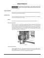
Operation and Care Of
FT1000i SERIES WASHERS
SAVE THESE INSTRUCTIONS
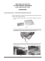
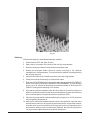
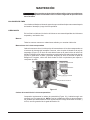
OPERATION
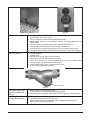
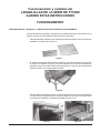
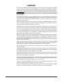
MACHINE PREPARATION – CHECK BEFORE BEGINNING OPERATION
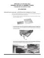
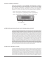
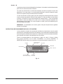
Open the machine doors and make sure all components are in their proper operating
positions before beginning operation.
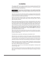
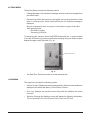
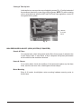
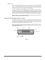
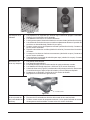
• All strainer pans and scrap baskets must be properly installed in each section
(Fig. 1).
Fig. 1
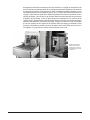
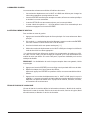
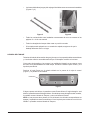
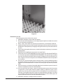
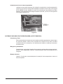
• The external scrap basket must be properly installed beneath the load section
of the machine (Fig. 2). For airline catering machines, ensure the external scrap
basket at the unload end of the machine is also properly installed.
Fig. 2
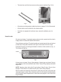
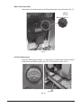
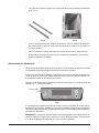
• All upper and lower wash arms must be properly installed in each section. Ensure
all wash arm end caps are properly installed and fully tightened (Figs 3 & 4).
Fig. 3 Fig. 4

– 5 –
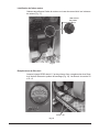
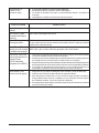
• The dual rinse and nal rinse arms must be properly installed (Figs. 5 & 6).
Fig. 5 Fig. 6
• All curtains must be properly installed as shown on pages 13-14 of this manual.
• All tank drains must be placed in the closed position.
• If machine is equipped with a blower dryer, ensure the deector pan is in
place.
TANK FILLING
All water (and steam, if equipped) supply valves must be opened and the electric
supply turned on before the machine will function.
Close all drains and doors. The drain handles are located near the oor at the front
of each tank. Swing drain handles to the right to close and to the left to open.
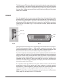
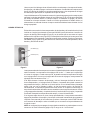
Press the Power key on the keypad located on the door of the control box (Fig. 7).
The display will light up.
POWER
Fig. 7
If door(s) are not closed, Door(s) Open displays. If drain(s) are not closed, Drain(s)
Open displays. If all doors and drains are closed, Tank(s) Filling displays and tanks
begin to ll.
NOTE: Opening a door during the ll cycle shuts off the ll valve, Door(s) Open
displays. Close the door to resume the ll cycle (Tanks Filling displays).
After the water level raises the lower oat in each tank, the wash, rinse and dual
rinse tanks begin to heat. When all tanks are full, the ll valves will automatically
shut off and the water temperatures in each tank are displayed on the control box
keypad display.

– 6 –
The Maintenance Fill feature adds water to the tanks to maintain proper water levels
during operation. If the water level drops below the lower oat in any tank, the heat
shuts off and lling resumes on the affected tank(s). When the water level reaches
the lower oat, heating resumes while the tank(s) continue(s) lling until the proper
water level is reached.
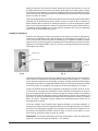
WASHING
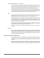
Start the motors for the conveyor, pumps and blower dryer (if equipped) by pressing
the green START switch located at either the load or unload end of the machine (Fig.
8) or on the keypad located on the front of the control box (Fig. 9). The machine
will operate only if the tanks have lled to the proper level and all doors are closed.
Press the red STOP switch (Fig. 8 or 9) to stop the conveyor, pumps and blower
dryer motors.
STOP (red)
START (green)
START
STOP
Fig. 8 Fig. 9
All tank temperatures display on the keypad display when the machine is in operation.
Final Rinse temperature reads ‘---‘ until product reaches the rinse zone. When
product reaches the rinse zone, the Final Rinse water temperature displays. After
the product exits the rinse zone, Final Rinse temperature again reads ‘---‘.
If product reaches the unload end of the machine and trips the dish limit switch, the
conveyor and nal rinse shut off, and the keypad displays the tank temperatures
along with Unload Dishes across the bottom. After the product is removed and the
dish limit returns to operating position, normal operation resumes. If product is not
unloaded, the Dish Limit Auto-Timer counts down for one minute, and then shuts
off pumps and blower dryer (if equipped). The display continues to show the tank
temperatures and Unload Dishes.
If no product enters the machine for a preset amount of time, the Auto-Timer
automatically shuts off the machine and tanks continue to maintain required
temperatures. To resume operation, press the green START switch located at either
end of the machine or on the keypad located on the front of the control box.
NOTE: The Auto-Timer shut off setting can be adjusted as shown in the Parameters
Menu (page 19); the range is from 1 to 30 minutes.

– 7 –
Empty Strainer Baskets As Necessary
The strainer baskets will ll with soil during operation which can affect machine
operation and wash results, therefore must be emptied periodically. STOP the
machine and open the access doors; strainer baskets are located immediately
inside at the front of the tanks.
The external scrap basket(s) at the load (all models) and unload (airline catering
units only) section needs to be emptied periodically, and can be done without
interrupting machine operation. Remove the basket(s) when lled with soil, empty
and replace when done.
Loading
Pre-scrap product thoroughly to remove large contaminants and debris. Never use
steel wool on product to be loaded into the machine; this could introduce surface
corrosion which could eventually interfere with machine operation.
For airline catering units, all plates, saucers, trays, etc. should be loaded on the
conveyor in an inclined position. Bowls should be loaded upside down. Silverware
must be washed in racks to prevent loss of items; failing to do so could cause the
conveyor to jam and damage ware or machine components.
DO NOT attempt to wash large items without rst checking to make sure they t
through the machine opening. Such items must not be washed in the machine
unless they will easily pass through.
DO NOT allow foreign objects to enter the unit, especially metallic contaminants.
Unloading
Remove product from the conveyor. If product pushes against the dish limit, the
conveyor stops and the pumps run for one minute before shutting off.
Unload the conveyor starting with the product furthest from the dish limit. Remove
the product that is striking the dish limit last. The machine automatically restarts.
RECOMMENDED MINIMUM TEMPERATURES
The water temperatures in the tanks and rinse arms are monitored electronically
and are displayed on the control box keypad display. The display should be checked
periodically to assure that proper temperatures are being maintained.
NOTE: Refer to the HOT WATER SANITIZING label on the side of the control box
for minimum temperature ratings. Does not apply to units equipped with a High
Pressure Blow Off (HPBO) drying system.

– 8 –
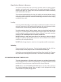
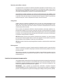
CONVEYOR SPEED ADJUSTMENT
Depending on the type of ware being washed, the conveyor speed can be adjusted
by pressing the SPEED SELECTION key located on the keypad on the front of the
control box (Fig. 10). When rst pressing the key, the current speed selection will
be shown on the bottom line of the display. By pressing the button a second or third
time, the speed will toggle to the next available selections;
Speed: Low (FT1000i: 4.0 FPM, FT1000iS: 4.0 FPM)
Speed: Medium (FT1000i: 6.3 FPM, FT1000iS: 5.2 FPM)
Speed: High (FT1000i: 8.5 FPM, FT1000iS: 6.3 FPM).
Fig. 10
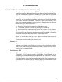
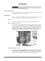
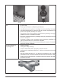
HIGH PRESSURE BLOW OFF (HPBO) SYSTEM (IF EQUIPPED)
The high pressure blow off system is designed to remove excess water from the top,
bottom, and side surfaces of items that have been washed. The system consists of
an external blower unit, either 10HP or 20HP, feeding high velocity air to a series of
air distribution devices including air knives, air cannons, and air nozzles targeting all
sides and surfaces of the items. The HPBO system may include single or multiple
chamber zones depending on the level of dryness required and/or overall machine
length constraints. The external blower unit can be installed adjacent to the unload
section located at oor level or mounted above the machine on optional tower frames.
The blower unit requires a separate dedicated power connection and is controlled
by a factory programmed VFD wired directly to the main control box of the FT1000i
machine. The blower system operation is integrated with the machine controls and
will turn on and off with the machine operation. The air knives and air cannons are
fully adjustable and can be directed specically to target various sizes and shapes
of items being washed. Blast gates are provided on the air hose connections as
an air ow damper control to the individual air knives, air cannons, and air nozzles.
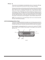
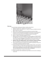
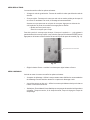
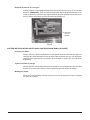
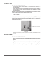
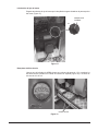
ADJUSTABLE RAIL SYSTEM (IF EQUIPPED)
The adjustable rail system is designed to facilitate washing a wide variety of container
sizes by allowing the operator to adjust a guide rail system integrated throughout
the entire length of the FT1000i machine, creating a wider or narrower “lane” for
the containers to travel through. It consists of two sets of guide rails; one xed
and one which is adjustable to accommodate varying sizes of containers. The rail
assembly mounted to the inside of the chambers on the front side of the machine
is xed. The rail assembly mounted to the inside of the chambers on the rear side
SPEED
SELECTION

– 9 –
of the machine is adjustable and pivots on hinged bracket supports mounted at the
chamber joints. The adjustment of the rear rail assembly is made by pulling the
locking pin from the adjustment bracket on the load end of the machine, pushing or
pulling the rail to the desired position, and then re-installing the locking pin (Fig. 11).
There are numerous adjustment positions that can be set using the incremental hole
positions in the adjustment bracket. Once the rail is set to the desired position and
secured with the locking pin it will remain in position until readjusted. The adjustable
rail system also incorporates vertical side wash tubes on the lower wash arms to
improve washing results. When the FT1000i machine is equipped with both the
adjustable rail system and the HPBO (high pressure blow off) system, the rear set
of side air cannons in the HPBO zone are mounted to the adjustable rail, allowing
the air cannons to adjust with the rail.
Fig. 11
REMOVE LOCKING PIN,
LOCATE RAIL TO DESIRED
POSITION & RE-INSTALL PIN

– 10 –
CLEANING
The machine MUST be thoroughly cleaned at the end of each working shift. Push
the POWER button on the keypad to turn the machine OFF. Follow the instructions
below for the manual cleaning process.
Disconnect the electrical power to the machine and follow
lockout/tagout procedures. There may be multiple circuits. Be sure all circuits
are disconnected.
Open all front access doors. Drain the machine by swinging the tank drain handles
to the left as shown on the labels located above each tank drain. Drain handles are
located near the oor at the front of each tank.
Remove and clean the curtains. Before removing the strainer baskets and pans,
clean the interior and all tank shelves using a hose and spray nozzle. Flush all
debris toward the strainers.
Remove the wash arms by lifting up on the arm clearing the tab from the notch in
the wash arm support. Slide upper arms forward, swinging front of arm down. Slide
lower arms forward, tilt front of arms upward to allow water to drain. Remove arms.
Clean wash arms in a sink, removing wash arm end caps to ush soil from arms.
Remove the strainer baskets and strainer pans. Also remove the dual rinse strainer.
Empty strainers in trash receptacle. DO NOT STRIKE STRAINER PANS OR
STRAINER BASKETS ON SOLID OBJECT TO DISLODGE DEBRIS. Scrub strainer
pans and strainer baskets in a sink.
Remove both dual rinse and upper nal rinse arms and clean debris from nozzles.
Never use steel wool to clean machine surfaces. Use only products formulated to
be safe on stainless steel.
Flush tanks with a water hose, removing any accumulation of soil.
Reinstall all arms and wash arm end caps in their proper location and orientation.
Ensure that upper arm nozzles point downward, and lower arm nozzles point upward.
To install wash arms, slide manifolds on the supports toward the rear of the machine
and ensure the tabs on the sides of the arms drop into the notches in the supports.
Replace the strainer pans and strainer baskets. Reinstall the curtains according
to the curtain diagrams shown on pages 13-14 of this manual. Leave the machine
doors open to allow the interior to air out and dry.
Clean machine exterior like any other stainless steel appliance. Use damp cloth
and mild soapy water.
Spray the channels where the sensors are located at the load end of the machine
(Fig. 12). Do not attempt to clean these with metallic objects as damage to sensors
can occur.

– 11 –
Fig. 12
Deliming
Follow these steps for manually deliming the machine.
1. Pow
er machine OFF and drain all tanks.
2. Spray interior of machine with a hose to ush soil into scrap baskets.
3. Remove, empty and clean all scrap baskets and strainer pans.
4. Disable the detergent feeder chemical system according to the chemical
manufacturer’s recommendation. This will prevent the addition of detergent during
the deliming operation.
5. Close all tank drains and re-install the strainer pans and scrap baskets.
6. Power the machine ON allowing it to ll with fresh water.
7. Refer to the PROGRAMMING section of this manual and adjust the AUTO TIMEOUT
time to 30 minutes by entering the MANAGER PROGRAMMING. This will allow the
unit to run for 30 minutes for the delime cycle without shutting off. Note the AUTO
TIMEOUT setting before adjusting to 30 minutes.
8. Once the ll cycle has completed, open the doors and pour the required amount of
delimer in each tank according to the chemical manufacturer’s instructions following
their recommendations for personal protective equipment (PPE).
9. Close the doors and start the machine allowing the pumps to run for 30 minutes at
normal operating temperatures.
10. After the 30 minutes has elapsed and the machine has timed out, open the doors
and inspect the interior for any remaining lime scale residue. If lime scale remains,
close the doors and run the machine for a longer period of time. Depending on the
time between deliming cycles and the water hardness, the machine may need to
run longer and/or adjust the amount of delimer being used.

– 12 –
11. Power machine OFF and drain all tanks.
12. Thoroughly spray the inside of the unit ushing the remaining delimer solution
down the drain.
13. Close all tank drains and power the machine ON allowing it to ll with fresh water.
14. Refer to the PROGRAMMING section of this manual and adjust the AUTO TIMEOUT
time back to the original setting as noted in Step 7 by entering the MANAGER
PROGRAMMING.
15. Once the ll cycle has completed, start the machine and run the pumps for a few
minutes to ush any remaining delimer from the system.
16. Power machine OFF and drain all tanks.
17. Following the chemical manufacturer’s recommendation, enable the detergent
feeder chemical system.
18. The unit is now ready for normal operation.
Certain areas of the machine, such as the loading, nal rinse, and unloading sections,
may still show signs of scale residue as these areas are not subjected to the recirculated
wash containing the deliming solution. These areas will need to be cleaned/delimed
manually as instructed below. DO NOT spray or wipe the deliming solution on
exterior surfaces of the machine as this could cause corrosion. If delimer solution
is accidentally contacted with the exterior of the machine, ush with water and
wipe. Always wear proper personal protective equipment (PPE) when using
delimer following chemical manufacturer’s recommendations.
1. Following the chemical manufacturer’s instructions, prepare a mixture of delimer
and water, and pour or brush the solution onto the surface to be cleaned.
2. Allow to soak for 10 minutes. If required, scrub to remove heavy deposits.
3. Rinse thoroughly with fresh water.
DOS AND DON'TS FOR YOUR NEW HOBART DISHWASHER
DO assure proper water hardness of 3 grains or less per gallon.
DO pre-scrap product thoroughly when soil/contamination levels are heavy and can be scrapped..
DO use only detergents recommended by your chemical professional.
DO, at the end of the day, complete a manual cleaning cycle as needed; thoroughly cleanse
the machine, rinse, and dry (leave doors open).
DO use only products formulated to be safe on stainless steel.
DO NOT use detergents formulated for residential dishwashers.
DO NOT allow soil to accumulate on the tank bottom.
DO NOT use steel wool to clean product or machine surface.
DO NOT allow foreign objects to enter the unit, especially metallic contaminants.
NOTE: Failure to follow use, care, and maintenance instructions may void your Hobart warranty.

– 13 –
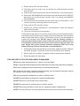
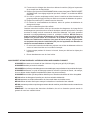
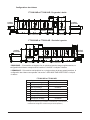
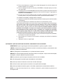
Curtain Congurations
* NOTE:
"WASH" section shown above.
** NOTE:
"BLOWER DRYER" section shown above.
FT1000i-IND & FT1000i-AIR - Left To Right
L
S
S
S
L L
L
L
LOAD
END
PREWASH WASH POWER
RINSE
DUAL
RINSE
BLOWER
DRYER
UNLOAD
END
See NOTE *
See NOTE * *
L
S
S
S
LL
L
L
LOAD
END
PREWASHWASHPOWER
RINSE
DUAL
RINSE
BLOWER
DRYER
UNLOAD
END
FT1000i-IND & FT1000i-AIR - Right To Left
See NOTE *
See NOTE * *
Curtain Location Curtain Part Number
S Load End 00-948731
L Load to Prewash 00-948729
S Prewash Arm 00-948731
L Prewash to Wash 00-948729
S Wash Arm 00-948731
L Power Rinse Arm 00-948729
L Dual Rinse 00-948729
L Blower Dryer 00-948729
FT1000i-IND & FT1000i-AIR
S - Designates short curtain.
L - Designates long curtain. (Curtains "Tiers" to face load end of machine when hung.)

– 14 –
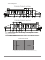
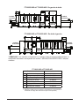
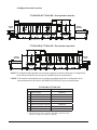
FT1000iS-IND & FT1000iS-AIR - Left To Right
LOAD
END
PREWASH WASH DUAL
RINSE
BLOWER
DRYER
UNLOAD
END
L
S
S
L LL
L
LOAD
END
PREWASHWASHDUAL
RINSE
BLOWER
DRYER
UNLOAD
END
L
S
S
LL L
L
* NOTE:
"BLOWER DRYER" section shown above.
FT1000iS-IND & FT1000iS-AIR - Right To Left
See NOTE *
See NOTE *
Curtain Location Curtain Part Number
S Load End 00-948731
L Load to Prewash 00-948729
S Prewash Arm 00-948731
L Prewash to Wash 00-948729
L Wash Arm 00-948729
L Dual Rinse 00-948729
L Blower Dryer 00-948729
FT1000iS-IND & FT1000iS-AIR
S - Designates short curtain.
L - Designates long curtain. (Curtains "Tiers" to face load end of machine when hung.)

– 15 –
PROGRAMMING
MACHINE OPERATION AND PROGRAMMING SECURITY LEVELS
The advanced digital controls on your FT1000i machine allow several setup and
customization options. Because these options can affect the operation of the machine,
they are all locked-out by default from the factory. To unlock them for editing, the
security level must be elevated to an appropriate level.
It is recommended to keep the machine in the lowest security level possible at all
times. This will prevent options from being inadvertently or intentionally modied
from what is expected or acceptable. The security level will automatically revert
back to the lowest allowable level (either Operator or SuperOperator, as described
below) when any of the following occur:
1. No keys on the keypad are pressed for 10 minutes or more.
2. The machine is placed in Standby by pressing the POWER key.
3. An invalid Security Code is entered on the ENTER SECURITY CODE? Screen.
The following names and descriptions of the various security levels are listed from
the lowest level to the highest level. A higher security level includes all of the abilities
of the lower levels plus some extra abilities, as described below.
NOTE: The security level does not, by itself, affect the operation of the machine or
inhibit the use of any of the Start, Stop, or Power keys or buttons. All of these basic
functions are always available in any security level.
Operator – O
This is the most basic security level and is enabled by default when the unit is
powered up as initially set by the factory. No security code is required to enter this
security level. This level only allows entering the Security Code to elevate the current
security level to something higher.
SuperOperator – SO
This security level can be enabled via the Manager Menu (Manager → Operation
Parameters → Super Operator Access). Once enabled, "Super Operator" will be
added as an option when the Menu button is pressed (in the "Main Menu"). A security
code is NOT required to enter the Super Operator menu once it has been enabled.
The Super Operator menu allows some advanced features to be accessed; such as
reviewing error logs and changing the displayed language. A detailed list of Super
Operator functions is shown in the Parameters Menu.

– 16 –
Manager – M
This security level is the highest level attainable by the user. It requires the Manager
Code to be entered before the security level will be elevated to Manager.
This security level offers unrestricted access to all of the options listed in the Parameters
Menu. Because of this, it is recommended that power to the machine be cycled off
and on when access to the Manager level options are no longer explicitly needed.
The Security Code for the Manager level can be changed by a manager or anyone
with the Manager Code. The default code is listed in the section titled Entering the
Operation Parameters Menu. As such, it is recommended that this code be changed
from the default and stored in a safe place where all managers, but no one else,
can access it. If the code is ever lost or forgotten, it can be reset by Hobart Service.
NOTE: Having Hobart Service reset the Manager Code is not covered under either
the basic or the extended warranty.
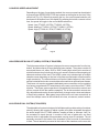
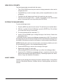
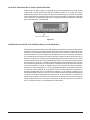
USER PROGRAMMING INSTRUCTIONS
The machine is equipped with electronic digital controls to allow greater precision for
cleaning your product, maintaining required tank temperatures and other advanced
functions. Some of these functions are customized to suit the needs of your operation.
All customization is performed through the on-screen menu using the UP, DOWN/
MENU, ENTER, and STOP/BACK keys located on the keypad on the control box
door (Fig. 13).
Fig. 13
START
STOP or BACK
POWER
SPEED
SELECTION
DOWN or
MENU
UPENTER DISPLAY

– 17 –
MENU DISPLAY PROMPTS
The following prompts are used inside the menus.
• The UP and DOWN arrow keys are used to change parameter values and to
navigate the menu.
• The ENTER key is used to accept a value, perform a specied action or enter
a submenu.
• The BACK key will always revert back to the previous menu screen.
• The text just to the right of the ‘>’ symbol on the display screen shows what
action or command will occur by pressing the ENTER key.
ENTERING THE MANAGER MENU
To enter the Manager menu:
1. Press the MENU key from the main screen. This will take you to the Main Menu.
2. With the ‘>’ symbol to the left of Manager, press the ENTER key. This will take
you to the Enter Security Code screen.
3. You are prompted with four asterisks [****].
4. Use the UP and DOWN keys to change the digit of the Security Code to the
appropriate value*.
* The default Security Code to enter Manager programming is 1001. This code can
be changed by anyone with this knowledge and it is recommended to change it from
the default. If the code is ever lost for some reason, it can be reset by Hobart Service.
NOTE: Resetting the code is not covered under your warranty, whether you are in
the initial warranty period or in the extended warranty period.
5. Press the ENTER key to move to the next digit to the right.
6. Repeat steps 4 and 5 for each digit.
After pressing ENTER on the fourth digit, you will be in the Manager Menu.
7. Press the UP or DOWN keys repeatedly until the ‘>’ symbol is to the left of the
desired option and then press the ENTER key. The Manager options are: About,
Actions, Logs, and Operation Parameters.
ABOUT SCREEN
The About screen displays the following information; Machine Model, Control Board
Revision, Relay Board Revision, Software Version, Sanitizing Mode, and Service
Number.

– 18 –
ACTIONS MENU
The Actions Menu provides the following options:
• Change Manager Code: Allows the manager security code to be changed from
the default value.
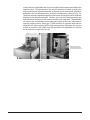
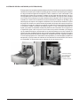
• Reverse Jog: Allows the conveyor to be jogged in the reverse direction in case
there is a conveyor jam. When entering this mode, the following message is
displayed:
Be sure all personnel clear of conveyor. Press button in upper Control Box
while pressing Enter.
> Exit without jogging
Reverse jog conveyor
To reverse jog the conveyor, press the ENTER button with the ‘>’ symbol located
to the left of Reverse jog conveyor while also pressing the green button located
behind the upper control box door (Fig. 14).
Fig. 14
• Set Date/Time: Enter this screen to set the date and time.
LOGS MENU
The Logs menu provides the following options:
• Delime Counter: Displays the time remaining before delime recommendation is
displayed. Also allows the ability to Clear Delime Counter.
• Error Log: Displays the previous errors along with the date/time the errors
occurred.
• Statistics: Entering the Statistics screen will display the following information;
Time of Operation, Run Time Percent, Rinse Time, and Fill Time.
REVERSE JOG BUTTON

– 19 –
OPERATION PARAMETERS MENU
NOTE: The parameters can be changed anytime the display is active, which is
when the machine is operating or in idle mode.
Hobart believes that the default settings that leave the factory are suitable for the
majority of operations. However, there are cases where managers may nd the
need to change one or more options; the Parameters Menu allows these changes.
Within the Parameters Menu, the manager (or operator, in some cases) may modify
factory default settings. The menu structure and description of each option are detailed
below. Please contact Hobart Service or Hobart Sales if you are uncomfortable
changing any setting or are unsure of which one(s) to change.
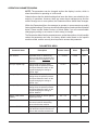
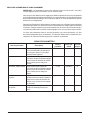
The Parameters Menu lists the parameter name, a short description, a list of possible
values the parameter can have, the factory default value based on the specic
machine model, and the security level required to access that parameter.
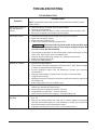
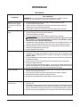
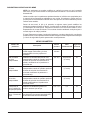
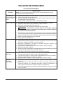
PARAMETERS MENU
Parameter Name Description Possible Values
Default
Value
Security
Required
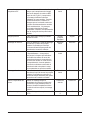
Auto Timeout
Adjustable timer for determining
when to shut down the pumps and
conveyor when no product is in the
machine.
1 – 30 mins 6 mins SO
Conveyor Speed High Sets the High conveyor speed
setting when the operator presses
the Speed Selection button on the
keypad changing the setting to
Speed: High.
4.0-8.5 8.5 ft/min M
Conveyor Speed Low Sets the Low conveyor speed
setting when the operator presses
the Speed Selection button on the
keypad changing the setting to
Speed: Low.
4.0-8.5 4.0 ft/min M
Conveyor Speed Medium Sets the Medium conveyor speed
setting when the operator presses
the Speed Selection button on the
keypad changing the setting to
Speed: Medium.
4.0-8.5 6.3 ft/min M
Delime – Main Tanks
Quantity
Sets the number of delimer gallons
required per tank.
0.0 – 2.0 0.50 M
Delime – Water Hardness Water hardness input setting which
the control uses for determining
when to delime the machine.
0 – 250 0 M
Dish Limit Till BD Heat Off Sets the period of time (in seconds)
until the blower dryer heat turns off
after a dish activates the dish limit.
0-60 seconds 60 seconds M

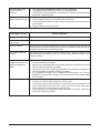
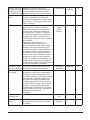
– 20 –
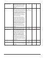
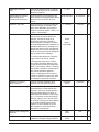
Dirty Water Interval Sets the period (in hours) of rinsing
before an alert is shown. This option
is only available when Dirty Water
Mode is set to “Alert” or to “Alert +
Lockout.”
1 – 6 hours 4 hours M
Dirty Water Mode Can be enabled to indicate that the
water may be dirty and may need to
be changed. Monitors the nal rinse
on time and when the nal rinse on
time exceeds a user-denable level,
a message will display. The message
will not be disabled until a water
change event occurs by draining all
tanks in the machine.
There are three different modes.
Disabled: Ignores dirty water. Alert :
Displays “Water Change Required”
after a period of operation but does
not require relling. Alert + Lockout:
Displays “Change Water Soon” for 5
minutes after a period of operation;
then “Water Change Required”
displays and the machine cannot
run until all tanks are drained and
relled.
Disabled
Alert
Alert + Lockout
Disabled M
Disable When Drain Open If enabled, prevents machine
operation if any tank drain is open.
Disabled
Enabled
Disabled M
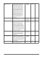
Energy Saver Time After a period of machine inactivity,
the control initiates Energy Saver
Mode: All machine components are
turned off, and the display on the
keypad dims, displaying “Energy
Saver On”. To exit Energy Saver
mode, press the STOP button on
the keypad. You may also press the
POWER button to completely turn
the machine off. If product is present
in machine, Energy Saver mode will
not activate.
1 – 6 hours 2 hours M
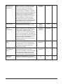
Final Rinse Flow Setting Low
High
Low M
Language Select Enables or disables the ability for
the operator to change the displayed
language.
Disabled
Enabled
Disabled SO
La page charge ...
La page charge ...
La page charge ...
La page charge ...
La page charge ...
La page charge ...
La page charge ...
La page charge ...
La page charge ...
La page charge ...
La page charge ...
La page charge ...
La page charge ...
La page charge ...
La page charge ...
La page charge ...
La page charge ...
La page charge ...
La page charge ...
La page charge ...
La page charge ...
La page charge ...
La page charge ...
La page charge ...
La page charge ...
La page charge ...
La page charge ...
La page charge ...
La page charge ...
La page charge ...
La page charge ...
La page charge ...
La page charge ...
La page charge ...
La page charge ...
La page charge ...
La page charge ...
La page charge ...
La page charge ...
La page charge ...
La page charge ...
La page charge ...
La page charge ...
La page charge ...
La page charge ...
La page charge ...
La page charge ...
La page charge ...
La page charge ...
La page charge ...
La page charge ...
La page charge ...
La page charge ...
La page charge ...
La page charge ...
La page charge ...
La page charge ...
La page charge ...
La page charge ...
La page charge ...
La page charge ...
La page charge ...
La page charge ...
-
 1
1
-
 2
2
-
 3
3
-
 4
4
-
 5
5
-
 6
6
-
 7
7
-
 8
8
-
 9
9
-
 10
10
-
 11
11
-
 12
12
-
 13
13
-
 14
14
-
 15
15
-
 16
16
-
 17
17
-
 18
18
-
 19
19
-
 20
20
-
 21
21
-
 22
22
-
 23
23
-
 24
24
-
 25
25
-
 26
26
-
 27
27
-
 28
28
-
 29
29
-
 30
30
-
 31
31
-
 32
32
-
 33
33
-
 34
34
-
 35
35
-
 36
36
-
 37
37
-
 38
38
-
 39
39
-
 40
40
-
 41
41
-
 42
42
-
 43
43
-
 44
44
-
 45
45
-
 46
46
-
 47
47
-
 48
48
-
 49
49
-
 50
50
-
 51
51
-
 52
52
-
 53
53
-
 54
54
-
 55
55
-
 56
56
-
 57
57
-
 58
58
-
 59
59
-
 60
60
-
 61
61
-
 62
62
-
 63
63
-
 64
64
-
 65
65
-
 66
66
-
 67
67
-
 68
68
-
 69
69
-
 70
70
-
 71
71
-
 72
72
-
 73
73
-
 74
74
-
 75
75
-
 76
76
-
 77
77
-
 78
78
-
 79
79
-
 80
80
-
 81
81
-
 82
82
-
 83
83


Hobart FT1000iS-IND Operation And Care Manual
- Taper
- Operation And Care Manual
- Ce manuel convient également à
dans d''autres langues
- English: Hobart FT1000iS-IND
- español: Hobart FT1000iS-IND
Documents connexes
-
Hobart FT1000S-ER-BD Mode d'emploi
-
-
Hobart CL44eNER Instructions Manual
-
-
-
-
Hobart LXeH ML-130192 Manuel utilisateur
-
-
-