
701 S. RIDGE AVENUE
TROY, OHIO 45374-0001
937 332-3000
www.hobartcorp.com
F44181 Rev. E (June 2013)
CLe-SERIES DISHWASHERS
BLOWER-DRYER
LAVE-VAISSELLE DE LA GAMME CLE
TUNNEL DE SÉCHAGE
LAVAVAJILLAS SERIE-CLE
SECADOR DE AIRE
ElEctric (cle SEriES) Ml-138211
ÉlEctriquE (gaMME cle) Ml-138212
SiStEMa ElÉctricO Ml-138213
(SEriE cle) Ml-138214
ElEctric (cler SEriES) Ml-138325
ÉlEctriquE (gaMME cler) Ml-138326
SiStEMa ElÉctricO Ml-138327
(SEriE cler) Ml-138328
StEaM (cle SEriES) Ml-138226
VapEur (gaMME cle) Ml-138227
SiStEMa a VapOr Ml-138228
(SEriE cle) Ml-138229
StEaM (cler SEriES) Ml-138333
VapEur (gaMME cler) Ml-138334
SiStEMa a VapOr Ml-138335
Ml-138336
E

– 2 –
TABLE OF CONTENTS
GENERAL ....................................................................3
INSTALLATION ................................................................3
Unpacking .................................................................3
Installation Codes ...........................................................3
CLeR Models ...............................................................3
Drill Holes .................................................................4
Mount Blower-Dryer to Dishwasher ..............................................6
Install Template/Stiffener ......................................................7
Mount Adjustable Legs .......................................................7
Adjust Blower-Dryer Feet for Firm Mounting .......................................7
AdjustAirDeector ..........................................................7
Install Connecting Rods .......................................................7
Track Adjustment ............................................................8
Dish Table Assembly .........................................................8
Mount Blower Motor ..........................................................9
Blower Motor Connections ................................................10
Electrical Connections .......................................................10
Control Connections .....................................................10
Power Connections .....................................................11
Blower Motor Rotation ...................................................12
Steam Connection (When Blower-Dryer is Equipped with Steam Heat) .................12
Condensate Return Piping ................................................14
Panel Assembly ............................................................16
Drain Connection ...........................................................16
Exhaust Connection .........................................................17
Adjusting the Vents on the Blower-Dryer and Dishwasher (hood or open canopy) .....18
OPERATION .................................................................20
CLEANING ..................................................................20
RemovingtheDeectorTray ..................................................20
Dos and Don'ts for Your New Hobart Warewasher .................................20
© HOBART 2009

– 3 –
Installation, Operation and Care Of
CLe and CLeR-SERIES BLOWER-DRYER
SAVE THESE INSTRUCTIONS
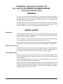
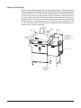
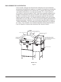
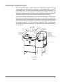
GENERAL
The CLe and CLeR series Blower-Dryer unit is designed to assist the drying of
dishware by drawing room air through a heated plenum into the unloading end of
the dishwasher. The unit is powered by a 2 HP electric motor and is available with
three-phase electric service only.
A condensation tight, forced exhaust system to the outside is necessary for removal
of humid drying air. This exhaust system is to be supplied by the customer. Refer
to Exhaust Connections for recommended exhaust requirements.
INSTALLATION
UNPACKING
Immediately after unpacking the blower-dryer, check for possible shipping damage.
If the machine is found to be damaged, save the packaging material and contact
the carrier within 15 days of delivery.
Priortoinstallation,verifythattheelectricalserviceagreeswiththespecications
on the machine data plate, which is located on the rear of the unit.
After unpacking the blower-dryer, remove the items that were shipped loose (hardware,
blower motor, legs) from inside the unit. Remove shipping braces and discard.
INSTALLATION CODES
Installation must be in accordance with state and local codes, or in the absence of
local codes, with the National Electrical Code ANSI / NFPA 70 (latest edition). In
Canada, the installation standard is: CSA C22.2 No. 1 (latest edition).
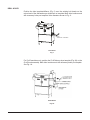
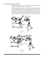
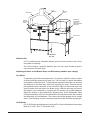
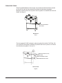
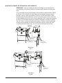
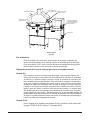
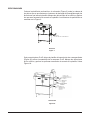
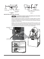
CLeR MODELS ONLY
Remove the side panels from the energy recovery hood assembly as shown in Fig.
1A. The side panels may be discarded; however, do not discard the hardware as
it will be reused.
InstallnewchamberangestoenergyrecoveryhoodassemblyasshowninFig.
1A using hardware removed in previous step.
Position the CleR blower dryer template (F-38373, Fig 2A) by aligning the front and
top edges of the template with the front and top edges of the energy recovery hood
as shown in Fig. 1A. Mark hole locations and drill necessary holes per template.
Hole diameters are shown in Fig. 2A.

– 4 –
CLe-Series
Fig. 1
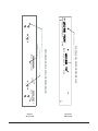
DRILL HOLES
Position the hole template/stiffener (Fig. 2) over the existing bolt heads on the
unload end of the dishwasher per directions on template. Mark hole locations and
drill necessary holes per template. Hole diameters shown in Fig. 2.
For CLeR machines only, position the CLeR blower-dryer template (Fig. 2A) on the
CLeR hood assembly. Mark hole locations and drill necessary holes per template.
See Fig. 1A.
CLeR-Series
Fig. 1A
HOLE
TEMPLATE / STIFFENER

– 5 –
Fig. 2
CLe and CLeR
CENTER PUNCH FOR 5/16" HOLE DIA, 7 PLC
CENTER PUNCH FOR 1-1/4" HOLE DIA, 2 PLC
CENTER PUNCH FOR 5/16" HOLE DIA, 6 PLC
HOLE TEMPLATE STIFFENER
CLeR BLOWER - DRYER TEMPLATE
Fig. 2A
CLeR Only

– 6 –
CLe-Series
Fig. 3
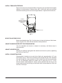
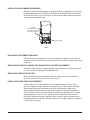
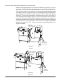
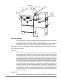
MOUNT BLOWER-DRYER TO DISHWASHER
NOTE: Thedishwashermustbeinitsnalposition,adjustedforproperheightand
properly leveled before blower-dryer can be mounted.
To mount the blower-dryer, apply the 1
1
⁄2" foam sealant tape (supplied) along the
edges of the dishwasher to prevent leakage (CLe models, see Fig. 3. CLeR models,
see Fig. 3A). Also apply the 5” foam sealant tape (supplied) below the tank lip on
the dishwasher (Fig. 3 and 3A). On CLeR models, insert two ¼-20 bolts into the
weld nuts on the end of the blower dryer chamber (Fig. 3A). These will be used
as locating studs. Position the blower-dryer against the dishwasher and assemble
using the ¼-20 bolts and nuts provided (Fig. 3 & 3A). Do not tighten at this time.
CLeR-Series
Fig. 3A
1/4-20 x (12)

– 7 –
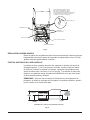
INSTALL TEMPLATE/STIFFENER
Remove knockouts from template/stiffener. Align the holes and attach the template/
stiffener to inside bottom of blower-dryer with 1/4-20 bolts and nuts provided.
Assemble remaining bolts and nuts through chamber. Tighten all bolts and nuts.
Fig. 4
ASSEMBLE
TEMPLATE/STIFFENER
TO INSIDE LOAD END
OF BLOWER-DRYER
(SEE FIG. 2)
RACK GUIDE
MOUNT ADJUSTABLE LEGS
Mount the adjustable legs (Fig. 3) to the last set of studs in the base of the blower-
dryer using the 5/16" nuts and lock washers already attached.
ADJUST BLOWER-DRYER FEET FOR FIRM MOUNTING
Turn the adjustable feet inward or outward, as necessary, until blower-dryer is
rmlymounted.
ADJUST AIR DEFLECTOR
Raisetheairdeectortightagainstthechamberandsecureinplacebytightening
the 5/16" bolt. See Fig. 5.
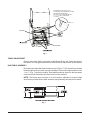
INSTALL CONNECTING RODS
Preassemble (1) elastic nut on each side of both rods, approximately 1.00" onto
the threads (Fig. 5). Route the connecting rods through the tank end. Assemble
the rods through the cross members of both cradles and add the second elastic
nut. Do not completely tighten the elastic nuts. A small gap of 0.15"- 0.020"
will allow better cradle alignment. Assure spacing between the last dog on the
parentmachineandtherstdogontheblowerdryerisequaldistanceinthefront
and rear of conveyor.

– 8 –
Fig. 5
ASSEMBLE ELASTIC STOP NUTS AT
END OF R
ODS FOR CORRECT ADJUSTMENT.
DO NOT OVERTIGHTEN NUTS.
THIS MAY CAUSE CONVEYOR TO BIND
0.15 - 0.020" GAP IS PREFERRED.
(4 PLACES)
TRACK ROD
APPROX.
1.00"
TANK END
Fig. 6
TRACK ADJUSTMENT
Place a rack on the track in the center of the Blower-Dryer unit. Verify that there is
less than 0.25" total gap between the rack and the track. Adjust track rod as needed.
DISH TABLE ASSEMBLY
Dishtablesshouldbettedintotheblower-dryer(Figs.6,7&8).Usesiliconesealant
between table and lip of tank to prevent leakage. Rack track height should be from
1
/4 to
5
/16" (Fig. 7) above the tank lip. Dish tables should be sloped so that any water
carried from the dishwasher will drain back into the machine.
NOTE: Theblower-dryermustbeinitsnalposition,adjustedforproperheight
and properly leveled before table assembly and plumbing connections are made.

– 9 –
Fig. 7
Fig. 8
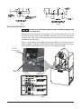
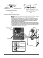
MOUNT BLOWER MOTOR
Take care when installing the blower motor to avoid damaging wiring
and electrical components.
Remove front and rear panels as necessary. The top and side panel unit can be
loosened on the exit side to ease installation. However, do not remove the top and
side panel unit. Take care to avoid damaging the wiring and electrical components
mounted on the side panel.
Apply 1" foam sealant tape (supplied) along the edges of the blower motor to
prevent leakage. Carefully position the blower motor over the opening in the blower-
dryer chamber top and bolt in place using 1/4-20 hardware provided.
Fig. 9
3-PHASE MOTOR
CONNECTIONS
GROUND
CONNECTION
LEVER TYPE WIRE
CONNECTORS
ELECTRONIC
OVERLOAD RELAY

– 10 –
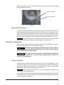
Mounttheprotectivemylarcovertotheplenumontopoftheblowerangeusing
blower hardware provided.
PROTECTIVE COVER
BLOWER HARDWARE
Fig. 10
Blower Motor Connections
Carefully route the blower motor cable through the p-clip, located at the center front
of the component baseplate, to the electronic overload relay. Connect the three-
phase wiring and ground pigtail leads from the overload relay to the blower motor
cable connections using the wire connectors. Refer to the blower motor connection
chart located on the blower motor for additional information (208/480 VAC only).
Make certain the blower motor cable and connections are securely routed
away from the motor fan blades to avoid damage to the connections.
ELECTRICAL CONNECTIONS
Beforemakingelectricalconnections,checkthemachinespecicationstoensure
that they agree with those of your electrical service.
Electrical and grounding connections must comply with the
applicable portions of the National Electrical Code, NFPA 70 (latest edition)
and / or other local electrical codes.
Disconnect the electrical power to the dishwasher and follow
lockout / tagout procedures. There may be multiple circuits. Be sure all
circuits are disconnected.
Control Connections
Carefully route the control cable to the control box on top of the dishwasher. Insert
the cable into the back of the control box through the strain relief (provided) and
collect extra cable inside control box. Use wire ties (provided) to secure cable
between the blower-dryer and dishwasher control box.
Make certain the control cable is securely routed along the top of the
dishwasher unit to avoid damage.
Connect the three control cable leads to the same-named terminal block connections
as shown in Fig. 11. Refer to the electrical diagram located inside the control box
cover for additional information.

– 11 –
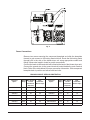
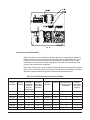
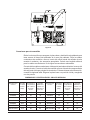
Power Connections
Remove two screws securing the component baseplate and slide the baseplate
forwardtogainaccesstoeldwiringterminalblock.Routetheeldwiringleads
through hole in the side of the blower-dryer unit using appropriate conduit and
ttings.Allowextralengthinleadsforproperconnections.
Connect the leads to the terminal block located at the back of the blower-dryer unit.
Connect the ground wire to the ground terminal located beside the main terminal
block. Refer to the table below for proper connection information. Slide component
baseplate back in position and secure with two bolts.
BRANCH CIRCUIT SIZE AND PROTECTION
Electric Steam
Electrical
Specs.
Rated
Amps
Min. Supply
Circuit
Conductor
Ampacity
Max.
Protective
Device Amps
Electrical
Specs.
Rated
Amps
Min. Supply
Circuit
Conductor
Ampacity
Max.
Protective
Device Amps
208/60/3 34.2 45 45 208/60/3 4.5 15 15
240/60/3 30.7 40 40 240/60/3 4.5 15 15
380/60/3 17.8 25 25 380/60/3 2.6 15 15
480/60/3 15.7 20 20 480/60/3 2.6 15 15
600/60/3 12.6 20 20 600/60/3 2.1 15 15
200/50/3 33.0 45 45 200-240/50/3 4.5 15 15
380-415/50/3 17.8 25 25 380-415/50/3 2.6 15 15
Fig. 11

– 12 –
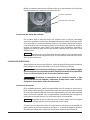
Blower Motor Rotation
Before placing the blower-dryer into service, check to verify that the
blower motor rotates in the correct direction (arrow in blower housing indicates
correct rotation). Incorrect rotation will result in unacceptable performance.
To check the blower motor's rotation:
Turn the power disconnect switch ON and momentarily activate the blower-dryer.
The main dishwasher must be operating during this procedure.
Be careful not to touch any uninsulated electrical parts that are exposed. If the
blower motor does not rotate in the proper direction, disconnect the electrical power
supply to the machine.
Disconnect the electrical power to the machine and follow
lockout / tagout procedures. There may be multiple circuits. Be sure all circuits
are disconnected.
Reverse any two of the blower motor cable leads at the overload relay using the
lever-type wire connectors. Reconnect the electrical power supply to the machine.
Re-check the blower motor's rotation.
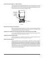
STEAM CONNECTION (When Blower-Dryer is Equipped with Steam Heat)
Steam supply pressure must agree with the steam trap (supplied) which
isratedfor10to50psigdifferentialpressure.Ifowingpressureexceeds50psig,
a pressure regulator (customer supplied) must be installed in the supply line. Steam
owiscontrolledbyasolenoidvalve.Twoconnectionsarerequired,oneforthe
steam supply and one for the condensate return.
The example shown depicts Right to Left direction. Left to Right will have plumbing
mirrored.
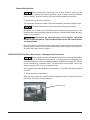
To install the steam connections:
With rear panel removed, install the elbow (shipped loose) to steam inlet line on
the blower dryer (pipe sealant required).
STEAM INLET LINE
Fig. 12

– 13 –
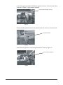
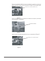
Locate inlet piping assembly 814498 and separate at union. Connect to the elbow
as shown in Figure 13 (pipe sealant required).
Partially install support bracket to the chamber with bolt and nut as shown below.
Install remaining portion of inlet piping assembly as shown in Figure 15.
INLET PIPING ASSEMBLY (814498)
Fig. 13
SUPPORT BRACKET
Fig. 14
INLET PIPING ASSEMBLY
Fig. 15

– 14 –
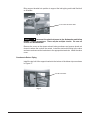
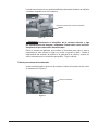
Bring support bracket into position to support the inlet piping and install 2nd bolt
on chamber.
Disconnect the electrical power to the dishwasher and follow
lockout / tagout procedures. There may be multiple circuits. Be sure all
circuits are disconnected.
Remove the cover on the steam solenoid valve enclosure and remove knock-out
closesttowherethecordwillberouted.Installthestrain-reliefttinginthevalve
enclosure and connect the lead wires to the appropriate terminals. Install the valve
cover.
Condensate Return Piping
Install the top half of the support bracket to the bottom of the blower dryer as shown
in Figure 17.
2nd SUPPORT BRACKET BOLT
Fig. 16
SUPPORT BRACKET
Fig. 17

– 15 –
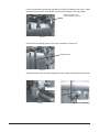
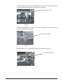
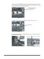
Locate condensate return piping assembly (814499) and break at the union. Install
the elbow on the outlet of the blower dryer heat exchanger as shown below.
Connect the remaining piping to the union as shown in Figure 19.
Install the steam trap and remaining piece of lower support bracket as shown below.
CONDENSATE RETURN
PIPING ASSEMBLY (814499)
Fig. 18
REMAINING PIPE
STEAM TRAP
LOWER BRACKET
Fig. 19
Fig. 20
Fig. 21

– 16 –
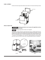
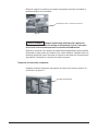
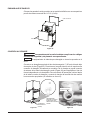
DRAIN CONNECTION
AT EITHER END
PANEL ASSEMBLY
Position front and rear panels and bolt in place with 1/4-20 truss head bolts provided.
DRAIN CONNECTION
Plumbing connections must comply with applicable sanitary,
safety and plumbing codes.
Plumbing equipment for drain is not supplied.
Connect the 1" drain connection under the blower-dryer to a suitable drain (Fig. 23).
The drain for the blower-dryer requires only one connection to the drain. On CLe
models only, the drain can be connected to the end of the common drain pipe (Fig.
24)forthedishwasherunitoritcanbeindependentlyconnectedtotheoordrain.
To connect to the dishwasher unit, remove the pipe plug from the common drain
pipeandconnecttheblower-dryerdrainusingappropriatettings(notsupplied).
REAR PANEL
FRONT PANEL
Fig. 22
Fig. 24
Fig. 23

– 17 –
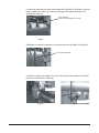
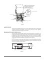
EXHAUST CONNECTION
Moist air escapes from each end of the conveyor type dishwasher. The recommended
exhaust requirement is 200 CFM (CLe and CLeR) at the entrance end of the dishwasher
and400CFM(CLe)/175CFM(CLeR)atthedischargeend.Sufcientmake-up
airmustbeprovidedsotheexhaustowresultsinapositivebuildingpressurein
the room in which the unit is located (more outside air than exhaust air). Hoods are
provided with 4" x 16" vent connectors with vent dampers which allow adjustment
during installation. Typical construction is for 'Pant-Leg' hood connections to the
4"x16"ventconnectors(Fig.25and25A).Ventstacksmustbewatertightandt
inside the vent connector openings.
CLe-Series
Fig. 25
4" X 16"
VENT
CONNECTOR
PA NT-LEG DUCT
ENTRANCE
VENT STACK
DAMPER
EXIT
VENT STACK
DAMPER
INTERNAL VENT
SHOULD REMAIN
OPEN UNLESS
AIRFLOW ADJUSTMENT
IS NECESSARY
DEFLECTOR PAN

– 18 –
Deflector Pan
OnCLemachinesonly,assembledeectorpanoverdrainconectionnuts.Panis
removable for cleaning.
On CLeRmachines, assemble deector pan over two studs located closest to
unload section of blower-dryer.
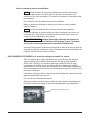
Adjusting the Vents on the Blower-Dryer and Dishwasher (hood or open canopy)
CLe-Series
To maintain good wash tank temperature, it is critical to adjust the vents to reduce
airowmovementcausedbythedryerfan.Therststepistoadjustdishwasher
vent system per Exhaust Spec. To help maintain tank heat, adjust the entrance and
exit dampers so the draw stops vapor from escaping into room. Excess draw can
pull tank heat from the entrance or exit of machine. Next, set the blower dryer vent
angle (located at the exit end of the blower dryer). Without removing any panels,
the damper can be adjusted by reaching into the chamber and rotating damper.
Adjust the damper to approximately 60 degrees. Next, let the dishwasher reach
minimal temperature, then turn the dishwasher ON and observe both the entrance
and discharge of the dishwasher. The curtains should be hanging nearly straight
down. If the discharge curtain is moving excessively make the following changes:
CLeR-Series
For CLeR-Series vent adjustments, refer to the CLe-Series dishwashers Instructions
Manual (F-44127, Rev. C, November 2012).
CLeR-Series
Fig. 25A
4" X 16"
VENT
CONNECTOR
PANT-LEG DUCT
ENTRANCE
VENT STACK
DAMPER
EXIT
VENT STACK
DAMPER
INTERNAL VENT
SHOULD REMAIN
OPEN UNLESS
AIRFLOW ADJUSTMENT
IS NECESSARY
DEFLECTOR PAN

– 19 –
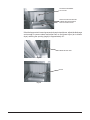
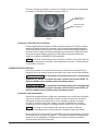
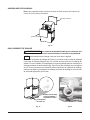
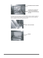
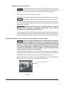
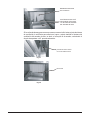
If the discharge curtain is moving excessively as pictured above, adjust the discharge
vent enough to remove steam and adjust vent on the blower dryer (air to blower
dryer) reducing the opening (angle) to approximately 45°.
EXCESSIVE MOVEMENT
OF CURTAIN
MAKE SURE DEFLECTOR AND
BLOWER DRYER ENTRANCE
BAFFLE ARE INSTALLED
Fig. 26
BLOWER-DRYER VENT
BAFFLE
Fig. 27
Fig. 28

– 20 –
OPERATION
The blower-dryer comes on anytime the pumps are ON. The blower-dryer remains
ON for approximately 15 seconds after the pumps have been turned OFF by
theauto-timerorthetablelimitswitch.If15secondsisinsufcient,timecanbe
increased to a maximum of 10 minutes. Contact Hobart Service for adjustment of
timer setting. The blower-dryer turns OFF immediately when the main machine
power switch is turned OFF.
If the Over Temperature light is ON, there is a failure in the
Blower Dryer. Contact Hobart Service immediately.
CLEANING
The machine must be thoroughly cleaned at the end of each working shift, or at
least twice a day. Use only products formulated to be safe on stainless steel. Use
a damp cloth and mild soapy water.
Never use steel wool to clean warewasher surfaces. Use only products
formulated to be safe on stainless steel.
Removing the Deflector Tray
Thedeectortraycanberemovedforcleaningandmaintenance.
DOs and DON'Ts for your New Hobart Blower-Dryer
DO pre-scrap dishes thoroughly.
DO, at the end of the day, thoroughly clean the machine, rinse and dry.
DO use only products formulated to be safe on stainless steel.
DO NOT allow food soil to accumulate on the tank bottom.
DO NOT use steel wool to clean ware or warewasher surfaces.
DO NOT allow foreign objects to enter the unit, especially metallic contaminants.
NOTE: Failure to follow use, care and maintenance instructions may void your
Hobart warewasher warranty.
F44181 Rev. E (June 2013)
PRINTED IN U.S.A.
La page est en cours de chargement...
La page est en cours de chargement...
La page est en cours de chargement...
La page est en cours de chargement...
La page est en cours de chargement...
La page est en cours de chargement...
La page est en cours de chargement...
La page est en cours de chargement...
La page est en cours de chargement...
La page est en cours de chargement...
La page est en cours de chargement...
La page est en cours de chargement...
La page est en cours de chargement...
La page est en cours de chargement...
La page est en cours de chargement...
La page est en cours de chargement...
La page est en cours de chargement...
La page est en cours de chargement...
La page est en cours de chargement...
La page est en cours de chargement...
La page est en cours de chargement...
La page est en cours de chargement...
La page est en cours de chargement...
La page est en cours de chargement...
La page est en cours de chargement...
La page est en cours de chargement...
La page est en cours de chargement...
La page est en cours de chargement...
La page est en cours de chargement...
La page est en cours de chargement...
La page est en cours de chargement...
La page est en cours de chargement...
La page est en cours de chargement...
La page est en cours de chargement...
La page est en cours de chargement...
La page est en cours de chargement...
La page est en cours de chargement...
La page est en cours de chargement...
La page est en cours de chargement...
La page est en cours de chargement...
-
 1
1
-
 2
2
-
 3
3
-
 4
4
-
 5
5
-
 6
6
-
 7
7
-
 8
8
-
 9
9
-
 10
10
-
 11
11
-
 12
12
-
 13
13
-
 14
14
-
 15
15
-
 16
16
-
 17
17
-
 18
18
-
 19
19
-
 20
20
-
 21
21
-
 22
22
-
 23
23
-
 24
24
-
 25
25
-
 26
26
-
 27
27
-
 28
28
-
 29
29
-
 30
30
-
 31
31
-
 32
32
-
 33
33
-
 34
34
-
 35
35
-
 36
36
-
 37
37
-
 38
38
-
 39
39
-
 40
40
-
 41
41
-
 42
42
-
 43
43
-
 44
44
-
 45
45
-
 46
46
-
 47
47
-
 48
48
-
 49
49
-
 50
50
-
 51
51
-
 52
52
-
 53
53
-
 54
54
-
 55
55
-
 56
56
-
 57
57
-
 58
58
-
 59
59
-
 60
60


dans d''autres langues
- English: Hobart ML-138228 User manual
- español: Hobart ML-138228 Manual de usuario
Documents connexes
Autres documents
-
Miele PTD 703 Le manuel du propriétaire
-
Honeywell T6 Pro Programmable Thermostat Le manuel du propriétaire
-
-
Herman Miller Motia Sit-to-Stand Tables Product Instructions
-
NUVO IRON HGCBHK01 Guide d'installation
-
Roper NGD5100TQ2 Guide d'installation
-
 Engel MRFD-015D-E Instructions For Use Manual
-
Miele PTD 901 Mode d'emploi
