
15C
20C
MFS
OB No.003-11090-6
E
OWNER’S MANUAL
F
MANUEL
DE L’UTILISATEUR
ES
MANUAL
DEL PROPIETARIO
D
BENUTZERHANDBUCH

MANUAL
15C
20C
MFS
OWNER’S
OB No.003-11090-6

ENOM00001-0
READ THIS MANUAL BEFORE USING THE OUTBOARD MOTOR. FAILURE TO FOLLOW THE
INSTRUCTIONS AND SAFETY PRECAUTIONS IN THIS MANUAL CAN RESULT IN SERIOUS
INJURY OR DEATH. KEEP THIS MANUAL IN A SAFE LOCATION FOR FUTURE REFERENCE.
Copyright © 2009-2012 Tohatsu Corporation. All rights reserved. No part of this manual may be reproduced
or transmitted in any from or by any means without the express written permission of Tohatsu Corporation.

3
YOUR TOHATSU OUTBOARD MOTOR
ENOM00002-0
OWNER REGISTRATION AND IDENTIFICATION
Upon purchasing this product, be sure that the WARRANTY CARD is correctly and com-
pletely filled out and mailed to the addressee noted there on. This WARRANTY CARD
identifies you as the legal owner of the product and serves as your warranty registration.
TO THE EXTENT PERMITTED BY APPLICABLE LAW, YOUR OUTBOARD MOTOR WILL
NOT BE COVERED BY THE APPLICABLE LIMITED WARRANTY, IF THIS PROCEDURE IS
NOT FOLLOWED.
ENOM00003-0
PRE-DELIVERY CHECK
Be sure that the product has been checked by an authorized TOHATSU dealer before you
take delivery.
ENOM00004-0
Limited Warranty
Please refer to the TOHATSU outboard motor Limited warranty provided to you with this
product, the terms and conditions of which, as amended from time to time, are incorpo-
rated by reference into the manual.

4
ENOM00005-0
Serial Number
In the space below, please record the outboard motor’s serial number (indicated both on
the lower motor cover and on the cylinder block). The serial number will be needed in the
event of theft or to quickly identifying the outboard motor type.
Serial Number:
ENOM00006-0
To You, Our Customer
Thank you for selecting a TOHATSU outboard motor. You are now the proud owner of an
excellent outboard motor that will service you for many years to come.
This manual should be read in its entirety and the inspection and maintenance procedures
described later in this manual should be followed carefully. Should a problem arise with the
outboard motor, please follow the troubleshooting procedures listed at the end of this
manual. If the problem persists, contact an authorized TOHATSU service shop or dealer.
We hope you will enjoy your outboard motor and wish you good luck in your boating
adventures.
TOHATSU CORPORATION

GENERAL SAFETY INFORMATION. . . . . . . . . . . . . . . . . . . . . . . . . . . . . . . .8
1. SPECIFICATIONS . . . . . . . . . . . . . . . . . . . . . . . . . . . . . . . . . . . . . . . . . . . . .10
2. NAMES OF PARTS . . . . . . . . . . . . . . . . . . . . . . . . . . . . . . . . . . . . . . . . . . . .12
3. LOCATION OF WARNING LABELS . . . . . . . . . . . . . . . . . . . . . . . . . . . . . . .14
4. INSTALLATION . . . . . . . . . . . . . . . . . . . . . . . . . . . . . . . . . . . . . . . . . . . . . . .18
1. Mounting the outboard motor on boat . . . . . . . . . . . . . . . . . . . . . . . . . . . 18
2. Installing the remote control devices . . . . . . . . . . . . . . . . . . . . . . . . . . . . .20
3. Installing the battery. . . . . . . . . . . . . . . . . . . . . . . . . . . . . . . . . . . . . . . . . .21
5. PRE-OPERATING PREPARATIONS . . . . . . . . . . . . . . . . . . . . . . . . . . . . . .23
1. Recommended gasoline types . . . . . . . . . . . . . . . . . . . . . . . . . . . . . . . . .23
2. Low permeation fuel hose requirement . . . . . . . . . . . . . . . . . . . . . . . . . . .24
EQUIPPED FOR UNITED STATES AND CANADA MODEL
3. EPA pressurized portable fuel tank requirements . . . . . . . . . . . . . . . . . . . 25
EQUIPPED FOR UNITED STATES AND CANADA MODEL
4. EPA approval Primer valve/hose assembly . . . . . . . . . . . . . . . . . . . . . . . .25
EQUIPPED FOR UNITED STATES AND CANADA MODEL
5. Recommended engine oil . . . . . . . . . . . . . . . . . . . . . . . . . . . . . . . . . . . . .26
6. Altitude adjustment kit requirement . . . . . . . . . . . . . . . . . . . . . . . . . . . . . . 26
7. Break-In . . . . . . . . . . . . . . . . . . . . . . . . . . . . . . . . . . . . . . . . . . . . . . . . . . .27
8. Engine oil warning lamp . . . . . . . . . . . . . . . . . . . . . . . . . . . . . . . . . . . . . . . 28
9. ESG (A device preventing over revolution). . . . . . . . . . . . . . . . . . . . . . . . .28
6. ENGINE OPERATION . . . . . . . . . . . . . . . . . . . . . . . . . . . . . . . . . . . . . . . . . . 29
Before starting . . . . . . . . . . . . . . . . . . . . . . . . . . . . . . . . . . . . . . . . . . . . . . . . 29
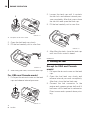
1. Filling the fuel . . . . . . . . . . . . . . . . . . . . . . . . . . . . . . . . . . . . . . . . . . . . . . .29
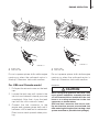
2. Feeding the fuel . . . . . . . . . . . . . . . . . . . . . . . . . . . . . . . . . . . . . . . . . . . . . 30
3. Starting. . . . . . . . . . . . . . . . . . . . . . . . . . . . . . . . . . . . . . . . . . . . . . . . . . . .32
4. Warming up the engine . . . . . . . . . . . . . . . . . . . . . . . . . . . . . . . . . . . . . . . 36
5. Forward and reverse . . . . . . . . . . . . . . . . . . . . . . . . . . . . . . . . . . . . . . . . .37
6. Stopping. . . . . . . . . . . . . . . . . . . . . . . . . . . . . . . . . . . . . . . . . . . . . . . . . . . 39
7. Trim angle . . . . . . . . . . . . . . . . . . . . . . . . . . . . . . . . . . . . . . . . . . . . . . . . .40
8. Tilt up, tilt down and shallow water operation . . . . . . . . . . . . . . . . . . . . . . 43
7. REMOVING AND CARRYING THE OUTBOARD MOTOR. . . . . . . . . . . . . . 48
1. Removing the outboard motor. . . . . . . . . . . . . . . . . . . . . . . . . . . . . . . . . . 48
2. Carrying the outboard motor . . . . . . . . . . . . . . . . . . . . . . . . . . . . . . . . . . .48
3. Storing the outboard motor . . . . . . . . . . . . . . . . . . . . . . . . . . . . . . . . . . . .48
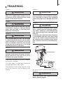
8. TRAILERING . . . . . . . . . . . . . . . . . . . . . . . . . . . . . . . . . . . . . . . . . . . . . . . . .49
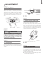
9. ADJUSTMENT . . . . . . . . . . . . . . . . . . . . . . . . . . . . . . . . . . . . . . . . . . . . . . . . 51
1. Steering friction . . . . . . . . . . . . . . . . . . . . . . . . . . . . . . . . . . . . . . . . . . . . .51
2. Throttle grip . . . . . . . . . . . . . . . . . . . . . . . . . . . . . . . . . . . . . . . . . . . . . . . .51
3. Remote Control Lever Load. . . . . . . . . . . . . . . . . . . . . . . . . . . . . . . . . . . . 51
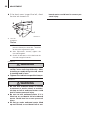
4. Trim Tab Adjustment . . . . . . . . . . . . . . . . . . . . . . . . . . . . . . . . . . . . . . . . .51
10. INSPECTION AND MAINTENANCE . . . . . . . . . . . . . . . . . . . . . . . . . . . . . . . 53
1. Daily Inspection . . . . . . . . . . . . . . . . . . . . . . . . . . . . . . . . . . . . . . . . . . . . .54
CONTENTS

2. Periodic Inspection . . . . . . . . . . . . . . . . . . . . . . . . . . . . . . . . . . . . . . . . . .60
3. Off-season storage . . . . . . . . . . . . . . . . . . . . . . . . . . . . . . . . . . . . . . . . . .65
4. Pre-season check . . . . . . . . . . . . . . . . . . . . . . . . . . . . . . . . . . . . . . . . . . .66
5. Motor submerged in water. . . . . . . . . . . . . . . . . . . . . . . . . . . . . . . . . . . . .66
6. Cold weather precautions . . . . . . . . . . . . . . . . . . . . . . . . . . . . . . . . . . . . .67
7. Checking after striking underwater object . . . . . . . . . . . . . . . . . . . . . . . . . 67
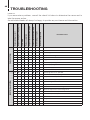
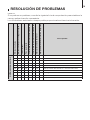
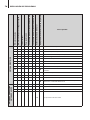
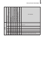
11. TROUBLESHOOTING . . . . . . . . . . . . . . . . . . . . . . . . . . . . . . . . . . . . . . . . . .68
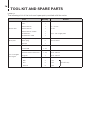
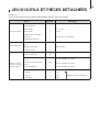
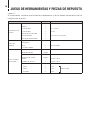
12. TOOL KIT AND SPARE PARTS . . . . . . . . . . . . . . . . . . . . . . . . . . . . . . . . . .70
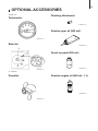
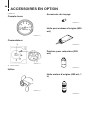
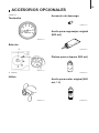
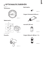
13. OPTIONAL ACCESSORIES . . . . . . . . . . . . . . . . . . . . . . . . . . . . . . . . . . . . . 71
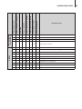
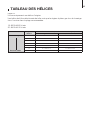
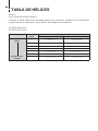
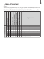
14. PROPELLER TABLE . . . . . . . . . . . . . . . . . . . . . . . . . . . . . . . . . . . . . . . . . . .72

7
GENERAL SAFETY INFORMATION
1. SPECIFICATIONS
2. NAMES OF PARTS
3. LOCATION OF WARNING LABELS
4. INSTALLATION
5. PRE-OPERATING PREPARATIONS
6. ENGINE OPERATION
7. REMOVING AND CARRYING THE
OUTBOARD MOTOR
8. TRAILERING
9. ADJUSTMENT
10. INSPECTION AND MAINTENANCE
11. TROUBLESHOOTING
12. TOOL KIT AND SPARE PARTS
13. OPTIONAL ACCESSORIES
14. PROPELLER TABLE
INDEX

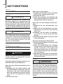
8
GENERAL SAFETY INFORMATION
ENOM00007-0
NOTICE: DANGER/WARNING/CAUTION/Note
Before installing, operating or otherwise handling your outboard motor, be sure to thor-
oughly read and understand this Owner’s Manual and carefully follow all of the instruc-
tions. Of particular importance is information preceded by the words “DANGER,”
“WARNING,” “CAUTION,” and “Note.” Always pay special attention to such information to
ensure safe operation of the outboard motor at all times.
ENOW00001-0
Failure to observe will result in severe personal injury or death, and possibly property dam-
age.
ENOW00002-0
Failure to observe could result in severe personal injury or death, or property damage.
ENOW00003-0
Failure to observe could result in personal injury or property damage.
ENON00001-0
Note
This instruction provides special information to facilitate the use or maintenance of the outboard
motor or to clarify important points.
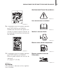
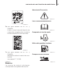
ENOM0008-0
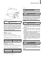
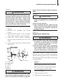
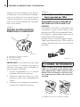
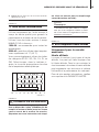
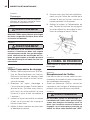
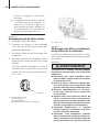
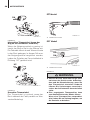
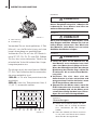
EMERGENCY STOP SWITCH
The Emergency Stop Switch will stall the outboard motor when the stop switch tether is
pulled off. This stop switch tether can be attached to the operator of the outboard motor
to minimize or prevent injuries from the propeller in case the operator falls overboard.
We highly recommend use of the Emergency Stop Switch tether.
ENOW00004-0
Accidental activation of the Emergency Stop Switch (such as the tether being pulled out in
heavy seas) could cause passengers to lose their balance and even fall overboard, or it
could result in loss of power in heavy seas, strong currents, or high winds. Loss of control
while mooring is another potential hazard.
To minimize accidental activation of the Emergency Stop Switch, the 500 mm (20 inch.) stop
switch tether is coiled and can extended to a full 1300 mm (51 inch.).
DANGER
WARNING
CAUTION
WARNING

GENERAL SAFETY INFORMATION 9
ENOM00009-0
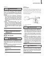
SAFE OPERATION OF BOAT
As the operator/driver of the boat, you are responsible for the safety of those aboard and
those in other boat around yours, and for following local boating regulations. You should
be thoroughly knowledgeable on how to correctly operate the boat, outboard motor, and
accessories. To learn about the correct operation and maintenance of the outboard motor,
please read through this manual carefully.
It is very difficult for a person standing or floating in the water to take evasive action should
he or she see a power boat heading in his/her direction, even at a slow speed. Therefore,
when your boat is in the immediate vicinity of people in the water, the outboard motor
should be shifted to neutral and shut off.
ENOW00005-0
SERIOUS INJURY IS LIKELY IF A PERSON IN THE WATER MAKES CONTACT WITH A MOV-
ING BOAT, GEAR HOUSING, PROPELLER, OR ANY SOLID DEVICE RIGIDLY ATTACHED TO
A BOAT OR GEAR HOUSING.
ENOM00010-0
SERVICING, REPLACEMENT PARTS & LUBRICANTS
We recommend that only an authorized service shop perform service or maintenance on
this outboard motor. Be sure to use genuine parts, genuine lubricants, or recommended
lubricants.
ENOM00011-0
MAINTENANCE
As the owner of this outboard motor, you should be acquainted with correct maintenance
procedures. It is the operator’s responsibility to perform all safety checks and to ensure
that all lubrication and maintenance instructions are complied with for safe operation.
Please comply with all instructions concerning lubrication and maintenance. You should
take the engine to an authorized dealer or service shop for periodic inspection at the pre-
scribed intervals.
Correct periodic maintenance and proper care of this outboard motor will reduce the
chance of problems and limit overall operating expenses.
ENOM00012-0
MOUNTING
Outboard motor mounting must be performed by trained service person(s) using lift or
hoist with sufficient capacity.
WARNING

10
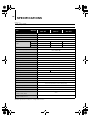
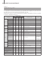
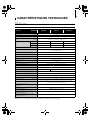
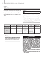
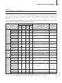
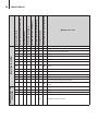
SPECIFICATIONS
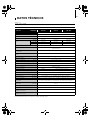
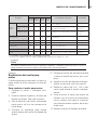
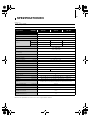
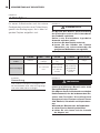
ENOM00301-0
*: with manual
Remark: Specifications subject to change without notice.
MF, EF, EFT
Item MODEL
15C MF
20C MF
15C EF
20C EF
15C EFT
20C EFT
Overall Length mm (in) 980 (38.6)
Overall Width mm (in) 365 (14.4)
Overall Height S·L·UL mm (in) 1065 (41.9) 1215 (47.8) 1342 (52.8)
Transom Height S·L·UL mm (in) 413 (16.3) 562 (22.1) 689 (27.1)
Weight
S kg (lb) 51.5 (114) 55.0 (121) 62.0 (136)
L kg (lb) 53.0 (117) 56.5 (125) 63.5 (139)
UL kg (lb) 54.5 (120) 58.0 (128) 65.0 (142)
Output kW (ps) 15C : 11.0 (15) 20C : 14.7 (20)
Max. Operating Range rpm
15C: 5000-6000
20C: 5400-6100
Idle Speed in Forward Gear rpm 900
Idle Speed in Neutral Gear rpm 950
Engine Type 4-Stroke
Number of Cylinder 2
Bore × Stroke mm (in) 61 × 60 (2.40 × 2.36)
Piston Displacement mL (Cu in) 351 (21.42)
Exhaust System Through hub exhaust
Cooling System Water cooling
Engine Lubrication Trochoid pump
Starting System Manual Electric starter motor*
Ignition System Flywheel Magneto C.D. ignition
Spark Plug NGK DCPR6E
Trim Position 6
Engine Oil mL (fl.oz.) API SF, SG, SH, SJ, SL or SM FCW 10W-30, Approx. 1000 (33.8)
Gear Oil mL (fl.oz.) Genuine Gear Oil or API GL5, SAE #80-90, Approx. 370 (12.5)
Fuel
Unleaded regular gasoline : Pump posted
87 Octane (research octane rating of 91)
Fuel Tank Capacity L (US gal) 12 (3.17)
Gear Reduction Ratio 2.15 (13 : 28)
Emission Control System EM (Engine modification)
Operator Sound Pressure
(ICOMIA 39/94) dB (A)
83.9
Hand Vibration Level
(ICOMIA 38/94) m/sec2
2.5

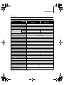
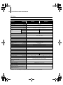
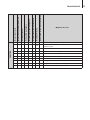
SPECIFICATIONS 11
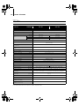
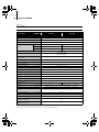
ENOM00302-0
*: with manual
Remark: Specifications subject to change without notice.
EP, EPT
Item MODEL
15C EP
20C EP
15C EPT
20C EPT
Overall Length mm (in) 640 (25.2)
Overall Width mm (in) 345 (13.6)
Overall Height S·L·UL mm (in) 1065 (41.9) 1215 (47.8) 1342 (52.8)
Transom Height S·L·UL mm (in) 413 (16.3) 562 (22.1) 689 (27.1)
Weight
S kg (lb) 54.0 (119) 61.0 (134)
L kg (lb) 55.5 (122) 62.5 (138)
UL kg (lb) 57.0 (126) —
Output kW (ps) 15C: 11.0 (15) 20C: 14.7 (20)
Max. Operating Range rpm
15C: 5000-6000
20C: 5400-6100
Idle Speed in Forward Gear rpm 900
Idle Speed in Neutral Gear rpm 950
Engine Type 4-Stroke
Number of Cylinder 2
Bore × Stroke mm (in) 61 × 60 (2.40 × 2.36)
Piston Displacement mL (Cu in) 351 (21.42)
Exhaust System Through hub exhaust
Cooling System Water cooling
Engine Lubrication Trochoid pump
Startring System Electric starter motor*
Ignition System Flywheel Magneto C.D. ignition
Spark Plug NGK DCPR6E
Trim Position 6 5
Engine Oil mL (fl.oz.) API SF, SG, SH, SJ, SL or SM FCW 10W-30/40, Approx. 1000 (33.8)
Gear Oil mL (fl.oz.) Genuine Gear Oil or API GL5, SAE #80-90, Approx. 370 (12.5)
Fuel
Unleaded regular gasoline: Pump posted
87 Octane (research octane rating of 91)
Fuel Tank Capacity L (US gal) 12 (3.17)
Gear Reduction Ratio 2.15 (13 : 28)
Emission Control System EM (Engine modification)
Operator Sound Pressure
(ICOMIA 39/94) dB (A)
83.9
Hand Vibration Level
(ICOMIA 38/94) m/sec2
—

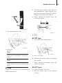
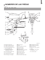
12
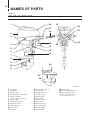
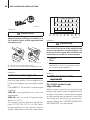
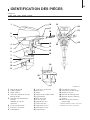
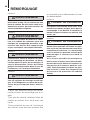
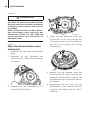
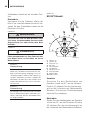
NAMES OF PARTS
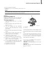
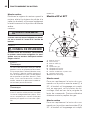
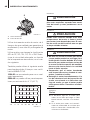
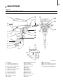
ENOM00303-0
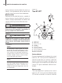
MF, EF, EP, EFT, EPT
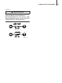
1
2
3
8
9
11
10
13
14
15
16
17
18
23
20
19
21
22
12
4
5
6
7
24
25
26
ENOF00301-0
1
Tilt Handle
2
Top Cowl
3
Bottom Cowl
4
Cooling Water Check Port
5
Power Tilt Switch
(EPT and EFT type only)
6
Oil Drain Bolt
7
Anti Ventilation Plate
8
Anode/Trim Tab
9
Sub Water Inlet
10
Water Inlet
11
Propeller
12
Drive Shaft Housing
13
Thrust Rod
14
Clamp Bracket
15
Clamp Screw
16
Throttle Grip
*1
17
Shift Lever
*1
18
Starter Handle
19
Stop Switch
20
Warning Lamp
21
Fuel Connector
22
Starter Switch
*2
23
Choke Knob
*1
24
Water Plug
25
Oil Plug (Upper) (Level)
26
Oil Plug (Lower) (Fill)
*1: MF, EF and EFT type only.
*2: EF and EFT type only.

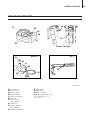
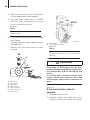
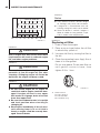
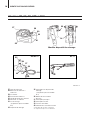
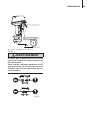
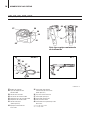
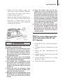
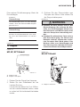
NAMES OF PARTS 13
MF, EF, EP, EFT, EPT
34
33
37
38
39
35
36
EP/EPT
*3
35
40
EFT
*4
27
28
30
29
31
32
ENOF00302-0
Power Tilt Type
27
Primer Bulb
28
Fuel Tank Cap
29
Air Vent Screw
30
Fuel Connector
31
Fuel Pick up Elbow
32
Fuel Tank
33
Clamp Screw
(EFT type only)
34
Power Tilt
35
Power Tilt Switch
(EPT type only)
36
Remote Control Box
37
Main Switch
38
Stop Switch
39
Cord Assembly
40
Engine Stop Switch Cord
*3: EP and EPT type only.
*4: EFT type only.

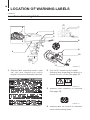
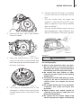
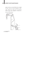
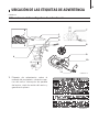
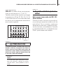
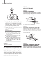
14
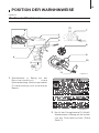
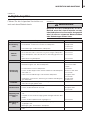
LOCATION OF WARNING LABELS
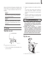
ENOM00305-0
1.
Warning label regarding owner’s man-
ual, top cowl, engine stop switch,
engine oil level and unleaded gasoline.
2.
Only for EU remote control model
Warning label regarding installation of
remote control system (See page 20).
3.
Warning label regarding oil pressure
(See page 28).
4.
Warning label on position of outboard
motor when setting down.
Locations of warning labels
1
2
3
4
11
5
6
9
8
10
7
ENOF00303-0
ENOF00005-0
ENOF00120-0
ENOF00131-0

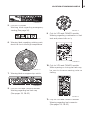
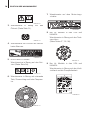
LOCATION OF WARNING LABELS 15
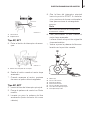
5.
Only for EU model
Warning label regarding emergency
starting (See page 34).
6.
Warning label regarding rotating parts,
electrical shock and high temperature.
7.
Warning label on engine stop switch.
8.
Only for USA and CANADA models
Warning regarding fuel tank cap
(See pages 25, 29–32).
9.
Only for USA and CANADA models
Warning regarding combination of fuel
tank and primer bulb ass’y.
10.
Only for USA and CANADA models
When opening or closing fuel tank cap,
be sure to observe warning note on
fuelling.
11.
Only for USA and CANADA models
Warning regarding fuel connector
(See pages 25, 29–32).
ENOF00006-0
ENOF00128-0
1
2
ENOF00129-0
ENOF00008-0
ENOF00012-0
ENOF00010-0
ENOF00011-0

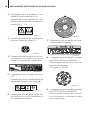
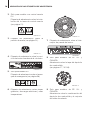
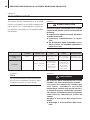
LOCATION OF WARNING LABELS16
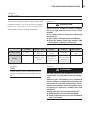
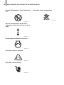
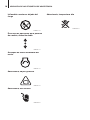
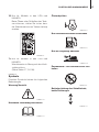
ENOM00023-0
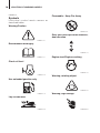
Symbols
Individual symbol marks means as
described below.
Warning/Caution
Read manual thoroughly
Check oil level
Use unleaded gasoline only
Lay as indicated
Flammable - Keep Fire Away
Gear shift lever operation direction,
dual direction
Engine start/Engine cranking
Warning, rotating object
Warning, high voltage
ENOF00114-0
ENOF00115-0
ENOF00116-0
ENOF00117-0
ENOF00118-0
ENOF00119-0
ENOF00122-0
ENOF00123-0
ENOF00249-0
ENOF00204-0

LOCATION OF WARNING LABELS 17
Warning, high temperature
ENOF00205-0

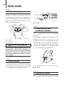
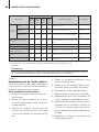
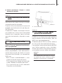
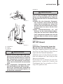
18
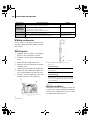
INSTALLATION
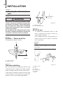
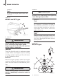
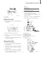
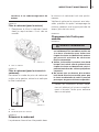
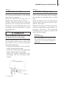
ENOM00024-0
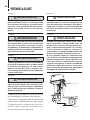
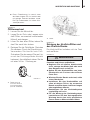
ENOW00006-0
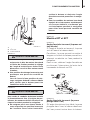
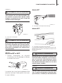
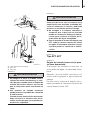
Most boats are rated and certified in terms
of their maximum allowable horsepower,
as shown on the boat’s certification plate.
Do not equip your boat with an outboard
motor that exceeds this limit. If in doubt,
contact your dealer.
Do not operate the outboard motor until it
has been securely mounted on the boat in
accordance with the instructions below.
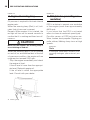
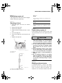
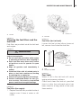
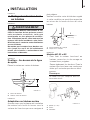
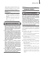
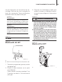
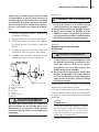
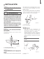
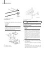
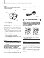
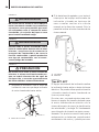
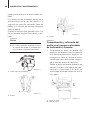
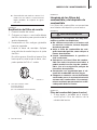
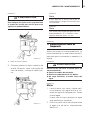
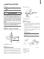
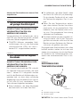
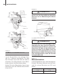
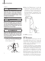
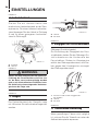
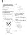
ENOM00025-0
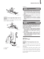
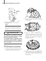
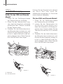
Position ... Above keel line
Set engine at center of boat.
1. Center of boat
2. Boat transom
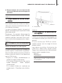
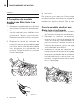
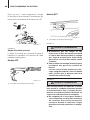
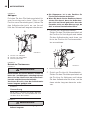
ENOM00509-0
Transom matching
Be sure that the anti ventilation plate of the
outboard motor is below the water surface
when running with the throttle wide open.
If the above condition cannot be met due
to the shape of the bottom of your boat,
please consult your authorized dealer.
1. Bottom of hull
2. Anti ventilation plate
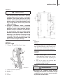
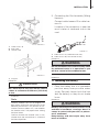
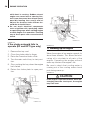
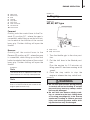
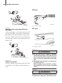
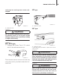
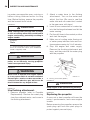
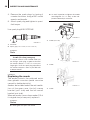
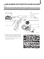
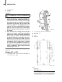
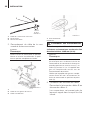
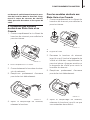
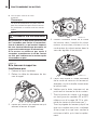
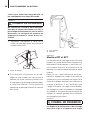
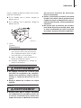
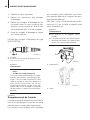
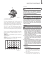
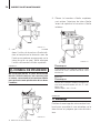
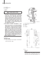
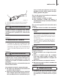
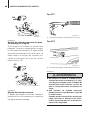
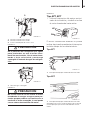
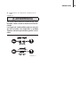
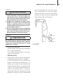
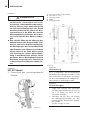
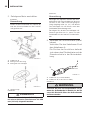
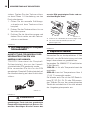
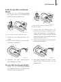
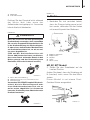
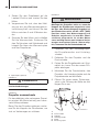
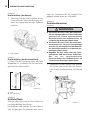
ENOM00306-0
MF, EF, EP type
1. To attach the outboard motor to the
boat, tighten the clamp screws by
turning their handles.
Also, tighten the bolts. Secure the out-
board motor with a rope to prevent
loss overboard.
ENON00002-0
Note
A rope is not included in the standard
accessories.
1. Bolt (8 × 85)*
2. Nut*
3. Washer*
4. Clamp screw
5. Washer*
*: Option
1. Mounting the outboard motor on
boat
WARNING
2
1
ENOF00014-0
1
2
5−25 mm
(0.2−1 in)
ENOF00015-0
1*
4
2*
3*
5*
ENOF00304-0

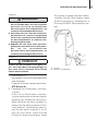
INSTALLATION 19
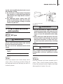
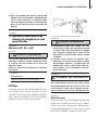
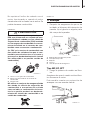
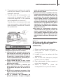
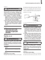
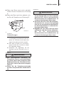
ENOW00007-0
z Before beginning the running test, check
that the boat with maximum capacity
loading floats on the water in a proper
attitude. Check the position of water
surface on the driveshaft housing. If the
water surface is near the bottom cowl-
ing, in high waves, water may enter the
engine cylinders.
z Incorrect outboard motor mounting
height or existence of underwater
object(s), such as hull bottom design,
bottom surface conditions or underwa-
ter accessories, can cause water spray
possibly reaching the engine through an
opening of the bottom cowling during
cruising. Exposing the engine to such
conditions for extended periods can
lead to severe engine damage.
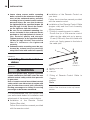
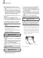
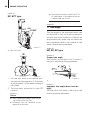
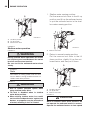
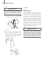
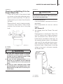
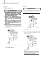
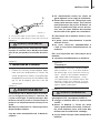
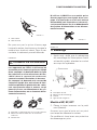
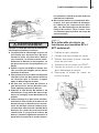
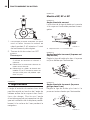
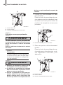
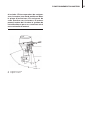
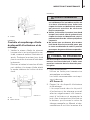
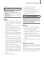
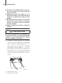
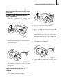
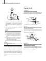
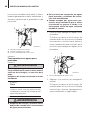
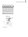
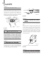
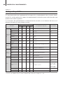
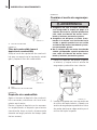
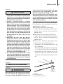
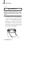
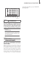
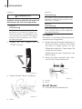
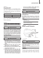
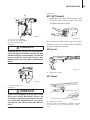
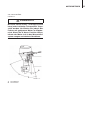
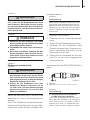
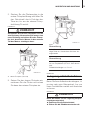
ENOM00309-0
EFT, EPT type
2. Power Tilt and Gas Assist type
1. Clamp screw (EFT type only)
2. Bolt (8 × 85)
3. Washer
4. Nut
5. Washer
View A
ENON00401-0
Note
It is recommended to install upper mounting
bolts with bolt head at inside surface of tran-
som. Bolts with threaded end at inside sur-
face of transom can cause personal injury.
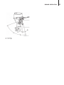
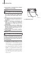
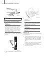
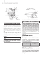
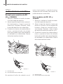
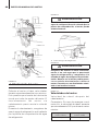
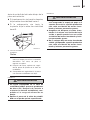
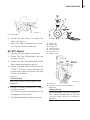
ENON00003-0
Notes
1. Apply sealing agent, such as silicone
sealed between the bolts and the tran-
som board holes before tightening the
bolts.
2. Be sure to tighten the mounting bolt
nuts to the specified torque.
(30 Nm (3.0 kgf) 13 ft-lb)
ENOW00009-0
z Mounting the outboard motor without
following this manual can lead to unsafe
conditions such as poor maneuverabil-
ity, lack of control or fire.
CAUTION
4
1
A
2
5
3
ENOF00308-0
WARNING
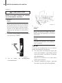
193
187
275
188
64
36
1818
1818
51
194
152
11
12- 10
ENOF00305-0
La page est en cours de chargement...
La page est en cours de chargement...
La page est en cours de chargement...
La page est en cours de chargement...
La page est en cours de chargement...
La page est en cours de chargement...
La page est en cours de chargement...
La page est en cours de chargement...
La page est en cours de chargement...
La page est en cours de chargement...
La page est en cours de chargement...
La page est en cours de chargement...
La page est en cours de chargement...
La page est en cours de chargement...
La page est en cours de chargement...
La page est en cours de chargement...
La page est en cours de chargement...
La page est en cours de chargement...
La page est en cours de chargement...
La page est en cours de chargement...
La page est en cours de chargement...
La page est en cours de chargement...
La page est en cours de chargement...
La page est en cours de chargement...
La page est en cours de chargement...
La page est en cours de chargement...
La page est en cours de chargement...
La page est en cours de chargement...
La page est en cours de chargement...
La page est en cours de chargement...
La page est en cours de chargement...
La page est en cours de chargement...
La page est en cours de chargement...
La page est en cours de chargement...
La page est en cours de chargement...
La page est en cours de chargement...
La page est en cours de chargement...
La page est en cours de chargement...
La page est en cours de chargement...
La page est en cours de chargement...
La page est en cours de chargement...
La page est en cours de chargement...
La page est en cours de chargement...
La page est en cours de chargement...
La page est en cours de chargement...
La page est en cours de chargement...
La page est en cours de chargement...
La page est en cours de chargement...
La page est en cours de chargement...
La page est en cours de chargement...
La page est en cours de chargement...
La page est en cours de chargement...
La page est en cours de chargement...
La page est en cours de chargement...
La page est en cours de chargement...
La page est en cours de chargement...
La page est en cours de chargement...
La page est en cours de chargement...
La page est en cours de chargement...
La page est en cours de chargement...
La page est en cours de chargement...
La page est en cours de chargement...
La page est en cours de chargement...
La page est en cours de chargement...
La page est en cours de chargement...
La page est en cours de chargement...
La page est en cours de chargement...
La page est en cours de chargement...
La page est en cours de chargement...
La page est en cours de chargement...
La page est en cours de chargement...
La page est en cours de chargement...
La page est en cours de chargement...
La page est en cours de chargement...
La page est en cours de chargement...
La page est en cours de chargement...
La page est en cours de chargement...
La page est en cours de chargement...
La page est en cours de chargement...
La page est en cours de chargement...
La page est en cours de chargement...
La page est en cours de chargement...
La page est en cours de chargement...
La page est en cours de chargement...
La page est en cours de chargement...
La page est en cours de chargement...
La page est en cours de chargement...
La page est en cours de chargement...
La page est en cours de chargement...
La page est en cours de chargement...
La page est en cours de chargement...
La page est en cours de chargement...
La page est en cours de chargement...
La page est en cours de chargement...
La page est en cours de chargement...
La page est en cours de chargement...
La page est en cours de chargement...
La page est en cours de chargement...
La page est en cours de chargement...
La page est en cours de chargement...
La page est en cours de chargement...
La page est en cours de chargement...
La page est en cours de chargement...
La page est en cours de chargement...
La page est en cours de chargement...
La page est en cours de chargement...
La page est en cours de chargement...
La page est en cours de chargement...
La page est en cours de chargement...
La page est en cours de chargement...
La page est en cours de chargement...
La page est en cours de chargement...
La page est en cours de chargement...
La page est en cours de chargement...
La page est en cours de chargement...
La page est en cours de chargement...
La page est en cours de chargement...
La page est en cours de chargement...
La page est en cours de chargement...
La page est en cours de chargement...
La page est en cours de chargement...
La page est en cours de chargement...
La page est en cours de chargement...
La page est en cours de chargement...
La page est en cours de chargement...
La page est en cours de chargement...
La page est en cours de chargement...
La page est en cours de chargement...
La page est en cours de chargement...
La page est en cours de chargement...
La page est en cours de chargement...
La page est en cours de chargement...
La page est en cours de chargement...
La page est en cours de chargement...
La page est en cours de chargement...
La page est en cours de chargement...
La page est en cours de chargement...
La page est en cours de chargement...
La page est en cours de chargement...
La page est en cours de chargement...
La page est en cours de chargement...
La page est en cours de chargement...
La page est en cours de chargement...
La page est en cours de chargement...
La page est en cours de chargement...
La page est en cours de chargement...
La page est en cours de chargement...
La page est en cours de chargement...
La page est en cours de chargement...
La page est en cours de chargement...
La page est en cours de chargement...
La page est en cours de chargement...
La page est en cours de chargement...
La page est en cours de chargement...
La page est en cours de chargement...
La page est en cours de chargement...
La page est en cours de chargement...
La page est en cours de chargement...
La page est en cours de chargement...
La page est en cours de chargement...
La page est en cours de chargement...
La page est en cours de chargement...
La page est en cours de chargement...
La page est en cours de chargement...
La page est en cours de chargement...
La page est en cours de chargement...
La page est en cours de chargement...
La page est en cours de chargement...
La page est en cours de chargement...
La page est en cours de chargement...
La page est en cours de chargement...
La page est en cours de chargement...
La page est en cours de chargement...
La page est en cours de chargement...
La page est en cours de chargement...
La page est en cours de chargement...
La page est en cours de chargement...
La page est en cours de chargement...
La page est en cours de chargement...
La page est en cours de chargement...
La page est en cours de chargement...
La page est en cours de chargement...
La page est en cours de chargement...
La page est en cours de chargement...
La page est en cours de chargement...
La page est en cours de chargement...
La page est en cours de chargement...
La page est en cours de chargement...
La page est en cours de chargement...
La page est en cours de chargement...
La page est en cours de chargement...
La page est en cours de chargement...
La page est en cours de chargement...
La page est en cours de chargement...
La page est en cours de chargement...
La page est en cours de chargement...
La page est en cours de chargement...
La page est en cours de chargement...
La page est en cours de chargement...
La page est en cours de chargement...
La page est en cours de chargement...
La page est en cours de chargement...
La page est en cours de chargement...
La page est en cours de chargement...
La page est en cours de chargement...
La page est en cours de chargement...
La page est en cours de chargement...
La page est en cours de chargement...
La page est en cours de chargement...
La page est en cours de chargement...
La page est en cours de chargement...
La page est en cours de chargement...
La page est en cours de chargement...
La page est en cours de chargement...
La page est en cours de chargement...
La page est en cours de chargement...
La page est en cours de chargement...
La page est en cours de chargement...
La page est en cours de chargement...
La page est en cours de chargement...
La page est en cours de chargement...
La page est en cours de chargement...
La page est en cours de chargement...
La page est en cours de chargement...
La page est en cours de chargement...
La page est en cours de chargement...
La page est en cours de chargement...
La page est en cours de chargement...
La page est en cours de chargement...
La page est en cours de chargement...
La page est en cours de chargement...
La page est en cours de chargement...
La page est en cours de chargement...
La page est en cours de chargement...
La page est en cours de chargement...
La page est en cours de chargement...
La page est en cours de chargement...
La page est en cours de chargement...
La page est en cours de chargement...
La page est en cours de chargement...
La page est en cours de chargement...
La page est en cours de chargement...
La page est en cours de chargement...
La page est en cours de chargement...
La page est en cours de chargement...
La page est en cours de chargement...
La page est en cours de chargement...
La page est en cours de chargement...
La page est en cours de chargement...
La page est en cours de chargement...
La page est en cours de chargement...
La page est en cours de chargement...
La page est en cours de chargement...
La page est en cours de chargement...
La page est en cours de chargement...
La page est en cours de chargement...
La page est en cours de chargement...
La page est en cours de chargement...
La page est en cours de chargement...
La page est en cours de chargement...
La page est en cours de chargement...
La page est en cours de chargement...
La page est en cours de chargement...
La page est en cours de chargement...
La page est en cours de chargement...
La page est en cours de chargement...
La page est en cours de chargement...
La page est en cours de chargement...
La page est en cours de chargement...
La page est en cours de chargement...
La page est en cours de chargement...
La page est en cours de chargement...
La page est en cours de chargement...
La page est en cours de chargement...
La page est en cours de chargement...
La page est en cours de chargement...
La page est en cours de chargement...
La page est en cours de chargement...
La page est en cours de chargement...
La page est en cours de chargement...
La page est en cours de chargement...
La page est en cours de chargement...
La page est en cours de chargement...
La page est en cours de chargement...
La page est en cours de chargement...
La page est en cours de chargement...
La page est en cours de chargement...
La page est en cours de chargement...
La page est en cours de chargement...
La page est en cours de chargement...
La page est en cours de chargement...
La page est en cours de chargement...
La page est en cours de chargement...
La page est en cours de chargement...
La page est en cours de chargement...
La page est en cours de chargement...
La page est en cours de chargement...
La page est en cours de chargement...
La page est en cours de chargement...
La page est en cours de chargement...
La page est en cours de chargement...
La page est en cours de chargement...
-
 1
1
-
 2
2
-
 3
3
-
 4
4
-
 5
5
-
 6
6
-
 7
7
-
 8
8
-
 9
9
-
 10
10
-
 11
11
-
 12
12
-
 13
13
-
 14
14
-
 15
15
-
 16
16
-
 17
17
-
 18
18
-
 19
19
-
 20
20
-
 21
21
-
 22
22
-
 23
23
-
 24
24
-
 25
25
-
 26
26
-
 27
27
-
 28
28
-
 29
29
-
 30
30
-
 31
31
-
 32
32
-
 33
33
-
 34
34
-
 35
35
-
 36
36
-
 37
37
-
 38
38
-
 39
39
-
 40
40
-
 41
41
-
 42
42
-
 43
43
-
 44
44
-
 45
45
-
 46
46
-
 47
47
-
 48
48
-
 49
49
-
 50
50
-
 51
51
-
 52
52
-
 53
53
-
 54
54
-
 55
55
-
 56
56
-
 57
57
-
 58
58
-
 59
59
-
 60
60
-
 61
61
-
 62
62
-
 63
63
-
 64
64
-
 65
65
-
 66
66
-
 67
67
-
 68
68
-
 69
69
-
 70
70
-
 71
71
-
 72
72
-
 73
73
-
 74
74
-
 75
75
-
 76
76
-
 77
77
-
 78
78
-
 79
79
-
 80
80
-
 81
81
-
 82
82
-
 83
83
-
 84
84
-
 85
85
-
 86
86
-
 87
87
-
 88
88
-
 89
89
-
 90
90
-
 91
91
-
 92
92
-
 93
93
-
 94
94
-
 95
95
-
 96
96
-
 97
97
-
 98
98
-
 99
99
-
 100
100
-
 101
101
-
 102
102
-
 103
103
-
 104
104
-
 105
105
-
 106
106
-
 107
107
-
 108
108
-
 109
109
-
 110
110
-
 111
111
-
 112
112
-
 113
113
-
 114
114
-
 115
115
-
 116
116
-
 117
117
-
 118
118
-
 119
119
-
 120
120
-
 121
121
-
 122
122
-
 123
123
-
 124
124
-
 125
125
-
 126
126
-
 127
127
-
 128
128
-
 129
129
-
 130
130
-
 131
131
-
 132
132
-
 133
133
-
 134
134
-
 135
135
-
 136
136
-
 137
137
-
 138
138
-
 139
139
-
 140
140
-
 141
141
-
 142
142
-
 143
143
-
 144
144
-
 145
145
-
 146
146
-
 147
147
-
 148
148
-
 149
149
-
 150
150
-
 151
151
-
 152
152
-
 153
153
-
 154
154
-
 155
155
-
 156
156
-
 157
157
-
 158
158
-
 159
159
-
 160
160
-
 161
161
-
 162
162
-
 163
163
-
 164
164
-
 165
165
-
 166
166
-
 167
167
-
 168
168
-
 169
169
-
 170
170
-
 171
171
-
 172
172
-
 173
173
-
 174
174
-
 175
175
-
 176
176
-
 177
177
-
 178
178
-
 179
179
-
 180
180
-
 181
181
-
 182
182
-
 183
183
-
 184
184
-
 185
185
-
 186
186
-
 187
187
-
 188
188
-
 189
189
-
 190
190
-
 191
191
-
 192
192
-
 193
193
-
 194
194
-
 195
195
-
 196
196
-
 197
197
-
 198
198
-
 199
199
-
 200
200
-
 201
201
-
 202
202
-
 203
203
-
 204
204
-
 205
205
-
 206
206
-
 207
207
-
 208
208
-
 209
209
-
 210
210
-
 211
211
-
 212
212
-
 213
213
-
 214
214
-
 215
215
-
 216
216
-
 217
217
-
 218
218
-
 219
219
-
 220
220
-
 221
221
-
 222
222
-
 223
223
-
 224
224
-
 225
225
-
 226
226
-
 227
227
-
 228
228
-
 229
229
-
 230
230
-
 231
231
-
 232
232
-
 233
233
-
 234
234
-
 235
235
-
 236
236
-
 237
237
-
 238
238
-
 239
239
-
 240
240
-
 241
241
-
 242
242
-
 243
243
-
 244
244
-
 245
245
-
 246
246
-
 247
247
-
 248
248
-
 249
249
-
 250
250
-
 251
251
-
 252
252
-
 253
253
-
 254
254
-
 255
255
-
 256
256
-
 257
257
-
 258
258
-
 259
259
-
 260
260
-
 261
261
-
 262
262
-
 263
263
-
 264
264
-
 265
265
-
 266
266
-
 267
267
-
 268
268
-
 269
269
-
 270
270
-
 271
271
-
 272
272
-
 273
273
-
 274
274
-
 275
275
-
 276
276
-
 277
277
-
 278
278
-
 279
279
-
 280
280
-
 281
281
-
 282
282
-
 283
283
-
 284
284
-
 285
285
-
 286
286
-
 287
287
-
 288
288
-
 289
289
-
 290
290
-
 291
291
-
 292
292
-
 293
293
-
 294
294
-
 295
295
-
 296
296
-
 297
297
-
 298
298
-
 299
299
-
 300
300
-
 301
301
-
 302
302
-
 303
303
-
 304
304
-
 305
305
-
 306
306
-
 307
307
-
 308
308
-
 309
309
-
 310
310
-
 311
311
-
 312
312
-
 313
313
-
 314
314
-
 315
315
-
 316
316
-
 317
317
-
 318
318
-
 319
319
-
 320
320
-
 321
321
-
 322
322


TOHATSU MFS 15 Le manuel du propriétaire
- Taper
- Le manuel du propriétaire
- Ce manuel convient également à
dans d''autres langues
- español: TOHATSU MFS 15 El manual del propietario
- Deutsch: TOHATSU MFS 15 Bedienungsanleitung
Documents connexes
Autres documents
-
Yamaha 25V Le manuel du propriétaire
-
Mercury 9.9 Operation and Maintenance Manual
-
-
Yamaha LF150 Le manuel du propriétaire
-
-
Suzuki DF 25 Le manuel du propriétaire
-
Simplicity 04500 Manuel utilisateur
-
-
-
Suzuki DF140A Le manuel du propriétaire