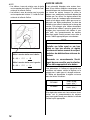
Suzuki DF300AP Le manuel du propriétaire
- Catégorie
- Moteur
- Taper
- Le manuel du propriétaire
Ce manuel convient également à

99011-98J20-03B
DF250AP/DF300AP
Part No. 99011-98J20-03B
June, 2012 Eng. Fre.
TK
300 TAKATSUKA, MINAMI, HAMAMATSU, JAPAN
Printed in Japan
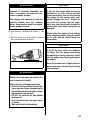
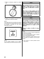
Keep with boat at all times.
This owner’s manual contains important
information on safety, operation and
maintenance.
OWNER’S MANUAL
Conserver ce manuel en permanence dans
le bateau. Ce manuel du proprietaire
contient d’importantes informations sur la
securite, le fonctionnement et l’entretien.
MANUEL DU PROPRIÉTAIRE
DF250AP/DF300AP
*99011-98J20-03B*

INDEX
ENGLISH
FRANÇAIS
________
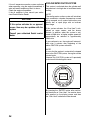
WIRING DIAGRAM
SCHEMA DE CABLAGE

1
ENGLISH
DF250AP
DF300AP
OWNER’S MANUAL
EN

2
IMPORTANT
WARNING/
CAUTION/ NOTICE/
NOTE
Please read this manual and follow its instruc-
tions carefully. To emphasize special informa-
tion, the symbol and the words WARNING,
CAUTION, NOTICE and NOTE have special
meanings. Pay special attention to the mes-
sages highlighted by these signal words.
NOTE:
Indicates special instructions to make mainte-
nance easier or instructions clearer.
BREAK-IN INFORMATION
FOR YOUR OUTBOARD MOTOR
The first 10 hours are the most important in the
life of your engine. Proper operation during this
break-in period is essential to help ensure max-
imum life and performance.
Refer to the BREAK-IN section of this manual
for specific break-in recommendations.
IMPORTANT NOTICE TO OWNERS
WARNING
Indicates a potential hazard that could
result in death or serious injury.
CAUTION
Indicates a potential hazard that could
result in minor or moderate injury.
NOTICE
Indicates a potential hazard that could
result in damage to the motor or boat.
WARNING
Failure to take the proper precautions
may increase the risk of death or severe
injury to you and your passengers.
• Prior to first-time use of your outboard
motor, familiarize yourself thoroughly
with the contents of this owner’s man-
ual. Be aware of all outboard motor fea-
tures and all safety and maintenance
requirements.
• Inspect the boat and motor before each
trip. See the INSPECTION BEFORE
BOATING section for important items.
• Become thoroughly familiar with all
operating and handling characteristics
of your boat and motor. Practice at low
and moderate speeds until you are
competent at handling the boat and
motor. Do not attempt to operate at max-
imum performance until you are com-
pletely familiar with all of these
characteristics.
• Carry boating safety and emergency
equipment. This important equipment
includes; flotation aids for each person
(plus one throwable buoyant cushion in
any boat 16 feet or longer), fire extin-
guisher, sound signaling device, visual
distress signals, anchor, bilge pump,
bucket, compass, emergency starter
rope, extra fuel and oil, first aid kit,
flashlight, food and water, mirror, pad-
dles, tool kit, and transistor radio. Be
sure you are carrying the equipment
appropriate for your trip before launch-
ing.
• Never start the engine or let it run
indoors or where there is little or no
ventilation. Exhaust gas contains car-
bon monoxide, a gas that is colorless
and odorless and can cause death or
severe injury.
• Instruct your passengers on how to
operate the boat, how to deal with
emergencies, and how to operate
safety and emergency equipment.
• Do not hold onto the motor cover or
any other parts of your outboard motor
while getting on or off your boat.
• Ensure that everyone wears a life jacket
on board.
• Never operate the boat while under the
influence of alcohol or other drugs.
• Distribute all weight load evenly in the
boat.
• Have all scheduled maintenance per-
formed. Consult your authorized
Suzuki marine dealer as required.
• Do not modify or remove any outboard
motor standard equipment. To do so
may make the motor unsafe to use.

3
NOTE:
Mounting radio transceiver or navigational
equipment antennae too close to the engine
cowling can cause electrical noise interference.
Suzuki recommends that antennae be mounted
at least one meter (40 inches) away from the
engine cowling.
• Learn and obey all applicable naviga-
tion rules.
• Pay attention to all weather forecasts.
Do not set out if weather is unsettled.
• Use extreme caution when purchasing
replacement parts or accessories.
Suzuki strongly recommends that you
use only genuine Suzuki replacement
parts/accessories or their equivalent.
Inappropriate or poor quality replace-
ment parts or accessories can create
unsafe operating conditions.
This manual should be considered a per-
manent part of the outboard motor and
should remain with the outboard motor
when resold or otherwise transferred to a
new owner or operator. Please read this
manual carefully before operating your
new Suzuki and review the manual from
time to time. It contains important infor-
mation on safety, operation, and mainte-
nance.
FOREWORD
The proper care and maintenance that your
outboard motor requires is outlined in this man-
ual. By following these instructions explicitly you
will ensure a long trouble-free operating life for
your outboard motor. This outboard motor also
conforms to the U.S Environmental Protection
Agency emission regulations which apply to
new outboard motors. The proper adjustment of
engine components is necessary for this out-
board motor to comply with the EPA regula-
tions. Therefore, please follow the maintenance
instructions closely to ensure emission compli-
ance. Your Suzuki dealer has experienced tech-
nicians that are trained to provide your outboard
motor with the best possible service with the
right tools and equipment.
All information in this manual is based on the
latest product information available at the time
of publication. Due to improvements or other
changes, there may be discrepancies between
this manual and your outboard motor. Suzuki
reserves the right to make production changes
at any time, without notice and without incurring
any obligation to make the same or similar
changes to an outboard motor previously built
or sold.

4
PLEASE PRESERVE NATURE
Protect and preserve your boating waters and
their land access. Never pollute the water or
land with oil, gas, or other harmful products. For
example, make sure you dispose of used gear
oil properly following a gear oil change. Also
remember not to litter. With a little bit of effort,
our boating waters can be enjoyed for many
years to come.
Suzuki Motor Corporation believes in conserva-
tion and protection of Earth’s natural resources.
To that end, we encourage every outboard
motor owner to recycle, trade in, or properly dis-
pose of, as appropriate, used oil and batteries.
TAKE A BOATING SAFETY CLASS
An educated boater will enjoy boating more and
will be a safer boater. We recommend that you
take a boating safety class.
Classes explaining required and recommended
equipment for small boats and offering training
in good seamanship are conducted by the U.S.
Coast Guard Auxiliary, the U.S. Power Squad-
ron, and many Red Cross chapters. For infor-
mation on classes in your area, call toll-free 1-
800-336-BOAT (2628).
Your state’s department of boating and your
Suzuki Marine dealer can supply you with addi-
tional information on boating safety and regula-
tions, or you can call the U.S. Coast Guard
Boating Safety Hotline toll-free at 1-800-368-
5647.
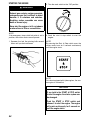
California Proposition 65 Warning
WARNING
Engine exhaust, some of its constituents
and certain product components contain
or emit chemicals known to the State of
California to cause cancer and birth
defects or other reproductive harm.
TABLE OF CONTENTS
FUEL AND OIL....................................... 6
GASOLINE............................................ 6
ENGINE OIL.......................................... 7
GEAR OIL ............................................. 7
LOCATION OF SAFETY LABELS ..... 8
LOCATION OF PARTS....................... 10
MOTOR INSTALLATION.................. 11
MOTOR INSTALLATION.................... 11
SELECTION OF LOWER UNIT
ROTATION..........................................
11
BATTERY INSTALLATION .............. 12
BATTERY REQUIREMENT ................ 12
BATTERY INSTALLATION ................ 12
SUB BATTERY CABLE...................... 13
DUAL BATTERY CHARGING
SYSTEM (OPTION).............................
14
USE OF ELECTRICAL
ACCESSORIES...................................
14
PROPELLER SELECTION AND
INSTALLATION................................... 14
IDENTIFICATION OF LOWER
UNIT ROTATION AND PROPELLER
TYPE SELECTION..............................
14
PROPELLER SELECTION ................. 16
PROPELLER INSTALLATION ........... 16
ADJUSTMENTS ................................... 17
TRIM ANGLE ADJUSTMENT............. 17
TRIM TAB ADJUSTMENT.................. 18
CONTROL HANDLE
ADJUSTMENT ....................................
19
IDLE SPEED ADJUSTMENT.............. 19
MOTOR COVER FASTENING
ADJUSTMENT ....................................
19
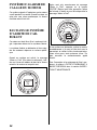
METER (OPTION) ............................... 20
BUTTON FUNCTIONS........................ 20
SCREEN.............................................. 20
LOCK PAGES..................................... 21
CLOCK................................................ 22
ALARM................................................ 22
CAUTION SYSTEM............................. 23
INDICATOR CHECK........................... 23
OVER-REVOLUTION CAUTION
SYSTEM..............................................
23
OIL PRESSURE CAUTION
SYSTEM..............................................
24
OIL TEMPERATURE CAUTION
SYSTEM..............................................
25
COOLING WATER CAUTION
SYSTEM..............................................
26
BATTERY VOLTAGE CAUTION
SYSTEM..............................................
28

5
ELECTRONIC THROTTLE AND
SHIFT CONTROL CAUTION
SYSTEM................................................. 29
CONTROL UNIT COMMUNICATION
CAUTION SYSTEM.............................
29
2ND STATION CAUTION SYSTEM.... 29
THROTTLE SYSTEM CAUTION
SYSTEM..............................................
30
SHIFT CONTROL CAUTION
SYSTEM..............................................
31
DIAGNOSTIC SYSTEM...................... 32
OIL CHANGE REMINDER
SYSTEM................................................. 33
SYSTEM ACTIVATION....................... 33
CANCELLATION ................................ 33
ENGINE STALLING CAUTION
SYSTEM................................................. 34
WATER IN FUEL ALERT SYSTEM. 34
OPERATION OF TILTING
SYSTEMS............................................... 35
POWER TRIM AND TILT.................... 35
TILT LIMITER CAM............................. 35
MANUAL TILTING .............................. 36
TILT LEVER ........................................ 36
INSPECTION BEFORE BOATING... 37
BREAK-IN ............................................. 39
OPERATION ......................................... 40
MAIN SWITCH (OPTION) ................... 40
CONTROL PANEL (OPTION)............. 40
BEFORE ATTEMPTING TO
START THE ENGINE..........................
43
STARTING THE ENGINE ................... 44
SHIFTING AND SPEED CONTROL ... 45
STOPPING THE ENGINE ................... 47
MOORING ........................................... 48
OPERATION IN SHALLOW
WATER................................................
48
OPERATING THE TROLL MODE
(Optional Item) ...................................
48
OPERATION IN SALT WATER .......... 49
OPERATION IN FREEZING
WEATHER...........................................
49
MOTOR REMOVAL AND
TRANSPORTING................................. 50
MOTOR REMOVAL ............................ 50
MOTOR TRANSPORTING.................. 50
TRAILERING........................................ 52
INSPECTION AND
MAINTENANCE................................... 53
NOTICE ............................................... 53
MAINTENANCE SCHEDULE ............. 53
SPARK PLUG ..................................... 55
BREATHER AND FUEL LINE ............ 57
ENGINE OIL........................................ 58
GEAR OIL ........................................... 59
LOW PRESSURE FUEL FILTER........ 61
LUBRICATION.................................... 62
CORROSION PREVENTION .............. 63
BATTERY............................................ 64
ENGINE OIL FILTER .......................... 65
FLUSHING THE WATER
PASSAGES............................................. 65
SUBMERGED MOTOR....................... 67
STORAGE PROCEDURE ................... 68
MOTOR STORAGE............................. 68
BATTERY STORAGE......................... 69
AFTER STORAGE ............................... 70
GENERAL INFORMATION............... 70
WARRANTIES (For U.S.A)................. 70
IDENTIFICATION NUMBER
LOCATION..........................................
70
EMISSION CONTROL
INFORMATION.................................... 71
TROUBLESHOOTING........................ 71
SPECIFICATIONS ............................... 74
FLOWCHART OF OIL CHANGE
REMINDER SYSTEM.......................... 74

6
FUEL AND OIL
GASOLINE
Suzuki highly recommends that you use alco-
hol-free unleaded gasoline whenever possible,
with a minimum pump octane rating of 89
((R+M)/2 method). In some areas, the only
fuels that are available are oxygenated fuels.
Oxygenated fuels which meet the minimum
octane requirement and the requirements
described below may be used in your outboard
motor without jeopardizing the New Outboard
Motor Limited Warranty.
NOTE:
Oxygenated fuels are fuels which contain oxy-
gen-carrying additives such as MTBE or alco-
hol.
Suzuki recommends that you install a water-
separating fuel filter assembly between your
boat’s fuel tank(s) and outboard motor(s). Fuel
filtration systems of this type will help prevent
water that may be present in your boat’s fuel
tank(s) from contaminating your motor’s elec-
tronic fuel injection system. Water contamina-
tion can cause poor engine performance and
can also cause damage to the electronic fuel
injection system components.
Your Authorized Suzuki Marine Dealer can pro-
vide you advice about water-separating fuel fil-
ter systems and installation.
NOTICE
Use of leaded gasoline can cause engine
damage. Use of improper or poor quality
fuel can affect performance and may
damage your motor and fuel system.
Use only unleaded gasoline. Do not use
fuel having lower than the recommended
octane, or fuel that may be stale or con-
taminated by dirt/water etc.
Gasoline Containing MTBE
Unleaded gasoline containing MTBE (Methyl
Tertiary Butyl Ether) may be used in your out-
board motor if the MTBE content is not greater
than 15%. This oxygenated fuel does not con-
tain alcohol.
Gasoline/Ethanol Blends
Blends of unleaded gasoline and ethanol (grain
alcohol), also known as gasohol, may be used
in your outboard motor if the ethanol content is
not greater than 10%.
Gasoline/Methanol Blends
Avoid using blends of unleaded gasoline and
methanol (wood alcohol) whenever possible.
DO NOT USE fuels containing more than 5%
methanol under any circumstances. Fuel sys-
tem damage or outboard motor performance
problems resulting from the use of such fuels
are not the responsibility of Suzuki and may not
be covered under the New Outboard Motor Lim-
ited Warranty.
Fuel containing 5% or less methanol may be
suitable for use in your outboard motor if they
contain cosolvents and corrosion inhibitors.
Fuel Pump Labeling
In some states, pumps that dispense oxygen-
ated fuels are required to be labeled for the type
and percentage of oxygenate, and whether
important additives are present. Such labels
may provide enough information for you to
determine if a particular blend of fuel meets the
requirements listed above. In other states,
pumps may not be clearly labeled as to the con-
tent or type of oxygenate and additives. If you
are not sure that the fuel you intend to use
meets these requirements, check with the ser-
vice station operator or the fuel suppliers.
NOTE:
• Be sure that any oxygenated fuel blend you
use has octane ratings of at least 89 pump
octane ((R+M)/2 method).
• If you are not satisfied with the driveability or
fuel economy of your outboard motor when
you are using a gasoline/alcohol blend, you
should switch back to unleaded gasoline con-
taining no alcohol.

7
• If engine pinging is experienced, substitute
another brand, as there are differences
between brands.
• Unleaded gasoline will extend spark plug life.
WARNING
Gasoline is extremely flammable and
toxic. It can cause a fire and can be haz-
ardous to people and pets.
Always take the following precautions
when refueling:
• Never permit anyone other than an
adult to refill the fuel tank.
• If you use a portable fuel tank, always
stop the motor and remove the fuel
tank from the boat to refill it.
• Do not fill the fuel tank all the way to
the top or fuel may overflow when it
expands due to heating by the sun.
• Be careful not to spill fuel. If you do,
wipe it up immediately.
• Do not smoke, and keep away from
open flames and sparks.
NOTICE
Gasoline kept in the fuel tank for long
periods of time will produce varnish and
gum, which can damage the engine.
Always use fresh gasoline.
NOTICE
Fuels containing alcohol can cause paint
damage, which is not covered under the
New Outboard Motor Limited Warranty.
Be careful not to spill fuel containing
alcohol while refueling. If fuel is spilled,
wipe it up immediately.
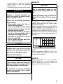
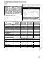
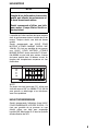
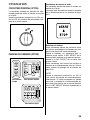
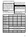
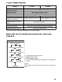
ENGINE OIL
Oil quality is a major contributor to your
engine’s performance and life. Always select
good quality engine oil.
Suzuki recommends the use of SAE 10W-40
SUZUKI MARINE 4-CYCLE ENGINE OIL. If
SUZUKI MARINE 4-CYCLE ENGINE OIL is not
available, select a NMMA certified FC-W oil or
good quality 4-cycle motor oil from the following
chart according to the average temperatures in
your area.
NOTE:
In very cold weather (below 5°C (41°F), use
SAE (or NMMA FC-W) 5W-30 for easier start-
ing and smooth operation.
GEAR OIL
Suzuki recommends the use of SUZUKI
HYPOID GEAR OIL. If it is not available, use
SAE 90 hypoid gear oil which is rated GL-5
under the API classification system.
NOTICE
Use of poor quality engine oil can
adversely affect engine performance and
life.
Suzuki recommends that you use Suzuki
Marine 4-Cycle Engine Oil or its equiva-
lent.
–20 –10 0 10 20 30
–4 14 32 50 68 86
40
104
TEMP.
API Classification
SAE Viscosity Grade
10W–40
10W–30
˚F
˚C
SG
SH
SJ
SL
SM

8
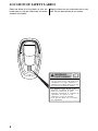
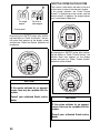
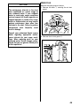
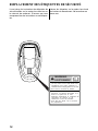
LOCATION OF SAFETY LABELS
Read and follow all of the labels on your out-
board motor or fuel tank. Make sure you under-
stand all of the labels.
Keep the labels on your outboard motor or fuel
tank. Do not remove them for any reason.
WARNING
AVERTISSEMENT
8
• Fuel can leak creating a fire hazard if
you lay motor on its side. Drain fuel
completely from vapor separator or
carburetor before laying motor on its side.
• See owner’s manual for details.
• Le carburant risque de fuir et de
présenter un danger d’incendie si le
moteur est placé sur le côté.
Vidanger entièrement le carburant du
séparateur de vapeurs ou du
carburateur avant de procéder.
• Pour plus de détail, voir le manuel
du propriétaire.

9

10
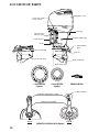
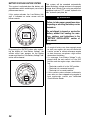
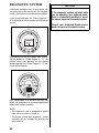
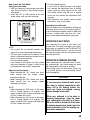
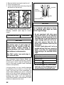
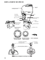
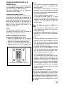
LOCATION OF PARTS
Engine oil drain plug
Flush plug
Clamp bracket
Anode
Water intake hole
Power trim and tilt
(P.T.T.) switch
Pilot water hole
(Reverse side)
Anti-cavitation
plate
Trim tab
Motor cover
Water intake hole
Gear oil level plug
Gear oil drain plug
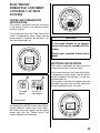
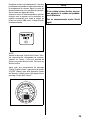
REMOTE CONTROL BOX (Option)
2 inch METER
(Option)
4 inch METER
(Option)
PRIMING BULB
Power trim and tilt (P.T.T.) switch
Remote control handle
Shift lock button
Type BType A

11
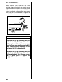
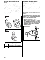
MOTOR INSTALLATION
MOTOR INSTALLATION
NOTE:
It is against federal regulations for any marine
dealer to service a motor that exceeds the rec-
ommended maximum horsepower for your
boat.
Suzuki strongly recommends that you have
your outboard motor, controls and gauges
installed by your authorized Suzuki Marine
Dealer. He has the tools, the facilities and the
know-how.
WARNING
Overpowering your boat can be hazard-
ous. Excessive horsepower will have an
adverse effect on hull safety and may
cause operating/handling difficulties. The
boat may also sustain stress and hull
damage.
Never install an outboard motor with
horsepower exceeding the manufac-
turer’s recommended maximum horse-
power listed on the boat’s “Certification
Plate”. Contact your authorized Suzuki
marine dealer if you are unable to locate
the hull “Certificate Plate”.
WARNING
Failure to have your outboard motor and
associated controls and gauges properly
installed can result in personal injury or
damage.
Suzuki strongly recommends that you
have your outboard motor, controls and
gauges installed by your authorized
Suzuki marine dealer. He has the tools,
the facilities, and the know-how to do the
job correctly.
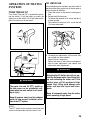
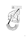
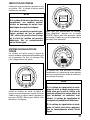
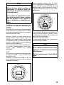
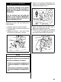
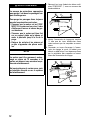
SELECTION OF LOWER UNIT ROTATION
Lower unit of this product can be used for both
regular rotation or counter rotation without
changing itself.
The motor will be shipped as regular rotation
specification from the factory.
To change the rotation from regular rotation to
counter, the rotation select connector located
near the low pressure fuel pump should be
changed from the original one to the optional
counter select one.
To return it to regular rotation, use the original
connector again.
Please contact your authorized Suzuki Marine
Dealer for details.
NOTE:
The selection of lower unit rotation closely
relates to the selection of the propeller type.
Confirm the lower unit rotation of the motor
before installing the propeller.
For propeller type selection, refer to the section
of “IDENTIFICATION OF LOWER UNIT ROTA-
TION AND PROPELLER TYPE SELECTION”.
Regular select connector
Counter select connector

12
NOTE:
Turn the main switch OFF before connecting or
disconnecting the rotation select connector.
BATTERY INSTALLATION
BATTERY REQUIREMENT
Choose a 12 Volt cranking-type lead acid bat-
tery that meets the specifications shown below.
1000 Marine Cranking Amps (MCA)/ABYC,
or 800 Cold Cranking Amps (CCA)/SAE
or 180 Reserve Capacity (RC) Minutes/SAE
NOTE:
• The specifications listed above are the mini-
mum battery rating requirements for starting
the engine.
• If your boat application requires additional
battery loads, it is recommended that an aux-
iliary battery or batteries be installed. Consult
your Suzuki dealer for proper battery installa-
tion information.
• Dual-purpose (Cranking/Deep-cycle) batter-
ies can be used if they meet the minimum
specifications listed above (MCA, CCA, or
RC).
• Do not use a Deep Cycle battery for the main
cranking battery.
• The use of Maintenance-Free, sealed, or Gel-
Cell batteries is not recommended because
they may not be compatible with Suzuki’s
charging system.
• When connecting batteries in parallel, they
must be of the same type, capacity, manufac-
turer, and of similar age. When replacement
is necessary, they should be replaced as a
set. Consult your Suzuki dealer for proper
battery installation information.
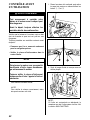
BATTERY INSTALLATION
Secure the battery in a dry area of the boat,
away from vibration.
NOTE:
• It is recommended that the battery be
installed in an enclosed battery case.
• When connecting batteries, hexagon-nuts
must be used to secure battery leads to bat-
tery posts.
To hook up the battery, first connect the red
lead from the motor to the positive battery ter-
minal, then connect the black lead to the nega-
tive battery terminal.
Red lead
Black
lead
Sub battery
cable
Hexagon-nut

13
To remove the battery, first disconnect the black
lead from the negative terminal, then discon-
nect the red lead from the positive terminal.
Connecting and disconnecting the battery as
described above will help minimize the chance
of creating an accidental short circuit and
sparks.
WARNING
If you place the battery near the fuel tank,
a spark from the battery may ignite the
gasoline, causing a fire and/or an explo-
sion.
Do not place the fuel tank in the same
compartment/area as the battery.
WARNING
Batteries produce flammable hydrogen
gas and may explode if they are near
flames or sparks.
Never smoke or cause sparks when work-
ing near the battery. Keep the battery
away from open flames. To avoid creating
a spark when charging the battery, con-
nect the battery charger cables to the
proper terminals before turning the
charger on.
WARNING
Battery acid is poisonous and corrosive.
It can cause severe injury and can dam-
age painted surfaces.
Avoid contact with eyes, skin, clothing,
and painted surfaces. If battery acid
comes in contact with any of these, flush
immediately with large amounts of water.
If acid contacts the eyes or skin, get
immediate medical attention.
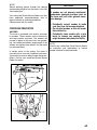
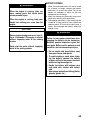
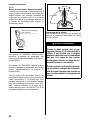
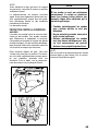
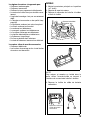
SUB BATTERY CABLE
The sub battery cable 1 is used to supply volt-
age to the engine control system. In the midst
of the cable, a 30 A fuse 2 is provided to pro-
tect the control circuit.
If the sub battery cable is not correctly con-
nected to the battery, engine cannot be started.
NOTICE
The electrical system or its components
may be damaged if proper battery pre-
cautions are not followed.
• Be sure to attach battery leads cor-
rectly.
• Do not disconnect battery leads from
the battery while the engine is running.

14
DUAL BATTERY CHARGING SYSTEM
(OPTION)
If installing the battery isolator lead assembly,
available as optional parts, and changing the
position of 40 A fuse from standard to option,
dual battery charging system will be effective.
Be sure to check if the optional 40 A fuse in
OPT position is blown, when the second battery
for accessories will not be charged.
Please ask your authorized Suzuki Marine
Dealer for installation of the isolator lead
assembly.
USE OF ELECTRICAL ACCESSORIES
The amount of power (12V DC) available for
accessories depends on the operating condi-
tion of the motor. For getting a detailed informa-
tion, please inquire of your authorized Suzuki
Marine Dealer.
NOTE:
Use of too much power for electrical accesso-
ries under certain operating conditions can
cause the battery to discharge.
PROPELLER SELECTION
AND INSTALLATION
IDENTIFICATION OF LOWER UNIT ROTA-
TION AND PROPELLER TYPE SELECTION
The lower unit rotation of this product can be
chosen between regular rotation and counter
rotation.
When shift into forward gear, the propeller shaft
of regular rotation lower unit rotates clockwise,
while the counter rotation lower unit rotates
counterclockwise as viewed from behind.
Before installing the propeller, confirm the lower
unit rotation type.
It is necessary to match the installed propeller
type to the lower unit type.
Install a right hand rotation propeller with
regular rotation lower unit, or left hand rota-
tion propeller with counter rotation lower
unit.
Please contact your authorized Suzuki Marine
Dealer for more detail.
WARNING
If a right hand rotation propeller is
installed on a counter rotation lower unit,
or a left hand rotation propeller on a regu-
lar rotation lower unit, the boat could go
in the opposite direction expected, which
could lead to an accident.
Do not use a right hand rotation propeller
with a counter rotation lower unit or a left
hand rotation propeller with a regular
rotation lower unit.

15
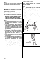
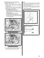
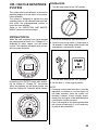
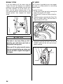
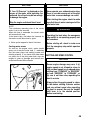
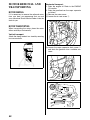
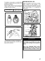
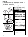
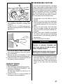
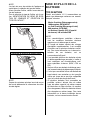
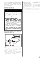
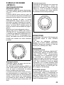
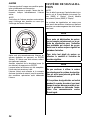
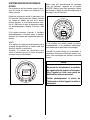
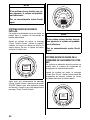
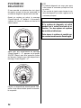
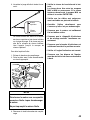
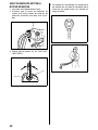
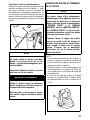
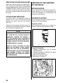
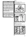
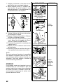
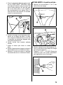
To identify the lower unit rotation type:
1. Remove the motor cover.
2. Confirm the rotation select connector
located near the low pressure fuel pump as
shown in figure.
In regular rotation lower unit and counter
rotation lower unit, rotation select connector
differ from the other as follow:
• For Regular rotation lower unit:
A blue rotation select connector 2 will be
found and there is a label “REGULAR” 1
on the connector.
• For Counter rotation lower unit:
A green rotation select connector 4 will
be found and there is a label “COUNTER”
3 on the connector.
Regular rotation lower unit
Counter rotation lower unit
3. The propeller type suitable for the lower unit
type should be selected and installed.
NOTE:
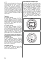
• Right hand rotation propellers are identified
with the letter “R” after the propeller size indi-
cation on the propeller.
• Left hand rotation propellers are identified
with the letter “L” after the propeller size indi-
cation on the propeller.
Right hand propeller:
3
× 16 × × R
Left hand propeller:
3
× 16 × × L

16
PROPELLER SELECTION
It is essential to use a propeller on your out-
board motor that is properly matched to your
boat’s operating characteristics. The speed of
the engine when you operate your boat at full
throttle depends on the propeller you use.
Excessive engine speed can seriously damage
the motor, while low engine speed at full throttle
will adversely affect the performance. Your
operating load will also affect propeller selec-
tion. Smaller loads generally require larger-
pitch propellers; larger loads generally require
smaller-pitch propellers. Your authorized Suzuki
Marine Dealer will assist you in selecting a suit-
able propeller for your boat.
You can determine if your propeller is appropri-
ate for use with your boat by using a tachome-
ter to measure engine speed when operating
your boat at full throttle, under minimum load
conditions. If you are using an appropriate pro-
peller, the engine speed will be within the fol-
lowing range:
If the engine speed is not within this range, con-
sult your authorized Suzuki Marine Dealer to
determine which propeller size is best for you.
If you change propellers, be sure to perform the
above check again, to confirm that the engine
speed under full throttle is within the specified
range.
NOTICE
Installing a propeller with either too much
or too little pitch will cause incorrect
maximum engine speed, which may
result in severe damage to the motor.
Ask your authorized Suzuki marine
dealer to assist you in selecting a suit-
able propeller for your boat.
DF250AP
5500 – 6100
r/min. (min
–1
)
DF300AP
5700 – 6300
r/min. (min
–1
)
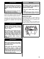
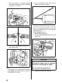
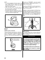
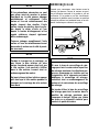
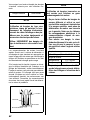
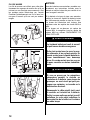
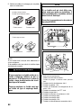
PROPELLER INSTALLATION
To install a propeller on your outboard motor,
use the following procedure:
1. Coat the propeller shaft splines 1 liberally
with Suzuki water resistant grease to help
prevent corrosion.
2. Place the stopper 2 on the shaft.
3. Align the propeller 3 with the propeller shaft
splines and slide the propeller onto the shaft.
4. Place the spacer 4 and washer 5 on the
shaft.
5. Install the propeller nut 6 and tighten it with
a torque wrench to 50 – 60 N·m (5.0 – 6.0
kg-m/36.0 – 43.5 lb-ft).
6. Align the grooves in the propeller nut with
the hole in the shaft, then insert the cotter
pin 7 and bend the pin ends over to lock it in
place.
To remove the propeller, reverse the above pro-
cedure.
WARNING
Failure to take proper precautions when
installing or removing the propeller can
result in severe personal injury.
When installing or removing the propeller:
• Always shift into “Neutral” and remove
the emergency stop switch lock plate
so that the motor cannot be started
accidentally.
• Wear gloves to protect hands, and
“lock” the propeller by placing a block
of wood between the blades and the
anti-cavitation plate.

17
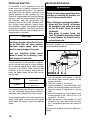
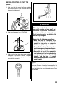
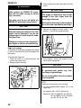
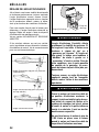
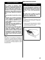
ADJUSTMENTS
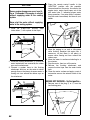
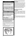
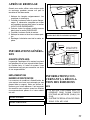
TRIM ANGLE ADJUSTMENT
To help maintain steering stability and good
performance, always maintain the proper trim
angle as shown in the illustration. The appropri-
ate trim angle varies depending on the combi-
nation of the boat, engine, and propeller, as well
as operating conditions.
Make a test run in the boat to determine if the
trim angle needs to be adjusted. Adjust the trim
angle using the Power Trim and Tilt system.
Refer to the POWER TRIM AND TILT section.
If you still cannot achieve good performance,
there may be a problem with engine mounting
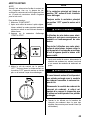
height. Consult your dealer for assistance.
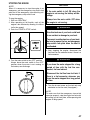
• Trim angle too small (Boat tends to “plow”)
•
Trim angle too large (Boat tends to “porpoise”)
• Proper trim angle
WARNING
Trim angle greatly affects steering stabil-
ity. If the trim angle is too small, the boat
may “plow” or “bow steer”. If the trim
angle is too large, the boat may “chine
walk” from side to side or “porpoise” up
and down. These conditions, which result
in loss of steering control, can cause
occupants to be thrown overboard.
Always maintain proper trim angle based
on the combination of your boat, engine,
and propeller, as well as operating condi-
tions.
WARNING
When the motor is tilted beyond the maxi-
mum trim position, the swivel bracket will
not have side support from the clamp
bracket and the tilt system will be unable
to cushion the engine if the lower unit
strikes an obstruction. This could lead to
occupant injury.
Do not operate the engine above 1500 r/
min or operate the boat in a planing atti-
tude with the motor tilted beyond the
maximum trim position.
Trim range
Tilt range

18
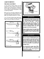
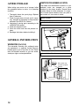
TRIM TAB ADJUSTMENT
This adjustment is used to compensate for the
possible tendency of your boat to veer slightly
to port or starboard. This tendency could be
due to such things as propeller torque, motor
mounting position, etc.
To adjust the trim tab:
1. Loosen the bolt A that holds the trim tab in
place.
NOTICE
If you operate the boat with the motor
trimmed beyond the maximum trim posi-
tion, the water intake holes may be above
the water line, causing severe engine
damage due to overheating.
Never operate the boat with the motor
trimmed beyond the maximum trim posi-
tion.
2. If the boat tends to veer to port, move the
rear end of the trim tab toward the port side.
If the boat tends to veer to starboard, move
the rear end of the trim tab toward the star-
board side.
3. Tighten the bolt that holds the trim tab in
place.
After adjusting the trim tab, check to see if the
boat still tends to veer to one side. If necessary,
readjust the trim tab.
La page est en cours de chargement...
La page est en cours de chargement...
La page est en cours de chargement...
La page est en cours de chargement...
La page est en cours de chargement...
La page est en cours de chargement...
La page est en cours de chargement...
La page est en cours de chargement...
La page est en cours de chargement...
La page est en cours de chargement...
La page est en cours de chargement...
La page est en cours de chargement...
La page est en cours de chargement...
La page est en cours de chargement...
La page est en cours de chargement...
La page est en cours de chargement...
La page est en cours de chargement...
La page est en cours de chargement...
La page est en cours de chargement...
La page est en cours de chargement...
La page est en cours de chargement...
La page est en cours de chargement...
La page est en cours de chargement...
La page est en cours de chargement...
La page est en cours de chargement...
La page est en cours de chargement...
La page est en cours de chargement...
La page est en cours de chargement...
La page est en cours de chargement...
La page est en cours de chargement...
La page est en cours de chargement...
La page est en cours de chargement...
La page est en cours de chargement...
La page est en cours de chargement...
La page est en cours de chargement...
La page est en cours de chargement...
La page est en cours de chargement...
La page est en cours de chargement...
La page est en cours de chargement...
La page est en cours de chargement...
La page est en cours de chargement...
La page est en cours de chargement...
La page est en cours de chargement...
La page est en cours de chargement...
La page est en cours de chargement...
La page est en cours de chargement...
La page est en cours de chargement...
La page est en cours de chargement...
La page est en cours de chargement...
La page est en cours de chargement...
La page est en cours de chargement...
La page est en cours de chargement...
La page est en cours de chargement...
La page est en cours de chargement...
La page est en cours de chargement...
La page est en cours de chargement...
La page est en cours de chargement...
La page est en cours de chargement...
La page est en cours de chargement...
La page est en cours de chargement...
La page est en cours de chargement...
La page est en cours de chargement...
La page est en cours de chargement...
La page est en cours de chargement...
La page est en cours de chargement...
La page est en cours de chargement...
La page est en cours de chargement...
La page est en cours de chargement...
La page est en cours de chargement...
La page est en cours de chargement...
La page est en cours de chargement...
La page est en cours de chargement...
La page est en cours de chargement...
La page est en cours de chargement...
La page est en cours de chargement...
La page est en cours de chargement...
La page est en cours de chargement...
La page est en cours de chargement...
La page est en cours de chargement...
La page est en cours de chargement...
La page est en cours de chargement...
La page est en cours de chargement...
La page est en cours de chargement...
La page est en cours de chargement...
La page est en cours de chargement...
La page est en cours de chargement...
La page est en cours de chargement...
La page est en cours de chargement...
La page est en cours de chargement...
La page est en cours de chargement...
La page est en cours de chargement...
La page est en cours de chargement...
La page est en cours de chargement...
La page est en cours de chargement...
La page est en cours de chargement...
La page est en cours de chargement...
La page est en cours de chargement...
La page est en cours de chargement...
La page est en cours de chargement...
La page est en cours de chargement...
La page est en cours de chargement...
La page est en cours de chargement...
La page est en cours de chargement...
La page est en cours de chargement...
La page est en cours de chargement...
La page est en cours de chargement...
La page est en cours de chargement...
La page est en cours de chargement...
La page est en cours de chargement...
La page est en cours de chargement...
La page est en cours de chargement...
La page est en cours de chargement...
La page est en cours de chargement...
La page est en cours de chargement...
La page est en cours de chargement...
La page est en cours de chargement...
La page est en cours de chargement...
La page est en cours de chargement...
La page est en cours de chargement...
La page est en cours de chargement...
La page est en cours de chargement...
La page est en cours de chargement...
La page est en cours de chargement...
La page est en cours de chargement...
La page est en cours de chargement...
La page est en cours de chargement...
La page est en cours de chargement...
La page est en cours de chargement...
La page est en cours de chargement...
La page est en cours de chargement...
La page est en cours de chargement...
La page est en cours de chargement...
La page est en cours de chargement...
La page est en cours de chargement...
La page est en cours de chargement...
La page est en cours de chargement...
La page est en cours de chargement...
La page est en cours de chargement...
La page est en cours de chargement...
La page est en cours de chargement...
La page est en cours de chargement...
La page est en cours de chargement...
-
 1
1
-
 2
2
-
 3
3
-
 4
4
-
 5
5
-
 6
6
-
 7
7
-
 8
8
-
 9
9
-
 10
10
-
 11
11
-
 12
12
-
 13
13
-
 14
14
-
 15
15
-
 16
16
-
 17
17
-
 18
18
-
 19
19
-
 20
20
-
 21
21
-
 22
22
-
 23
23
-
 24
24
-
 25
25
-
 26
26
-
 27
27
-
 28
28
-
 29
29
-
 30
30
-
 31
31
-
 32
32
-
 33
33
-
 34
34
-
 35
35
-
 36
36
-
 37
37
-
 38
38
-
 39
39
-
 40
40
-
 41
41
-
 42
42
-
 43
43
-
 44
44
-
 45
45
-
 46
46
-
 47
47
-
 48
48
-
 49
49
-
 50
50
-
 51
51
-
 52
52
-
 53
53
-
 54
54
-
 55
55
-
 56
56
-
 57
57
-
 58
58
-
 59
59
-
 60
60
-
 61
61
-
 62
62
-
 63
63
-
 64
64
-
 65
65
-
 66
66
-
 67
67
-
 68
68
-
 69
69
-
 70
70
-
 71
71
-
 72
72
-
 73
73
-
 74
74
-
 75
75
-
 76
76
-
 77
77
-
 78
78
-
 79
79
-
 80
80
-
 81
81
-
 82
82
-
 83
83
-
 84
84
-
 85
85
-
 86
86
-
 87
87
-
 88
88
-
 89
89
-
 90
90
-
 91
91
-
 92
92
-
 93
93
-
 94
94
-
 95
95
-
 96
96
-
 97
97
-
 98
98
-
 99
99
-
 100
100
-
 101
101
-
 102
102
-
 103
103
-
 104
104
-
 105
105
-
 106
106
-
 107
107
-
 108
108
-
 109
109
-
 110
110
-
 111
111
-
 112
112
-
 113
113
-
 114
114
-
 115
115
-
 116
116
-
 117
117
-
 118
118
-
 119
119
-
 120
120
-
 121
121
-
 122
122
-
 123
123
-
 124
124
-
 125
125
-
 126
126
-
 127
127
-
 128
128
-
 129
129
-
 130
130
-
 131
131
-
 132
132
-
 133
133
-
 134
134
-
 135
135
-
 136
136
-
 137
137
-
 138
138
-
 139
139
-
 140
140
-
 141
141
-
 142
142
-
 143
143
-
 144
144
-
 145
145
-
 146
146
-
 147
147
-
 148
148
-
 149
149
-
 150
150
-
 151
151
-
 152
152
-
 153
153
-
 154
154
-
 155
155
-
 156
156
-
 157
157
-
 158
158
-
 159
159
-
 160
160
-
 161
161
-
 162
162


Suzuki DF300AP Le manuel du propriétaire
- Catégorie
- Moteur
- Taper
- Le manuel du propriétaire
- Ce manuel convient également à
dans d''autres langues
- English: Suzuki DF300AP Owner's manual
Documents connexes
Autres documents
-
Yamaha LF150 Le manuel du propriétaire
-
Mercury 9.9 Operation and Maintenance Manual
-
-
TOHATSU MFS 15 Le manuel du propriétaire
-
Edgewater Networks Center Console 228 Owner Assistance Manual
-
Yamaha F4A Le manuel du propriétaire
-
-
-
 Saito Engines SAIEG100TS Le manuel du propriétaire
-
 CPED Kit de filtration Pilotéphos Révolution Mode d'emploi

